
P2 T - Lamp Cameo - Free user manual and instructions
Find the device manual for free P2 T Cameo in PDF.
| Product type | LED Profile Spot (Ellipsoidal) |
| Brand | Cameo |
| Model | P2 T (CLP2T) |
| Category | Professional lighting fixture |
| Light source | LED COB 230 W, warm white |
| Color temperature | 3266 K (nominal 3200 K) |
| Luminous flux (motor) | 13,984 lm |
| Beam angle (with optional lenses) | 19°, 26°, 36°, 50°, zoom 15°-30°, zoom 25°-50° |
| Dimmer | 16-bit, curves: linear, exponential, logarithmic, S |
| Strobe | 0 Hz – 20 kHz |
| Control protocols | DMX512, RDM, W-DMX (optional) |
| DMX modes | 1CH, 2CH 16bit, 2CH Strobe, 3CH, 4CH, 5CH |
| Power supply | 100 – 240 V AC, 50/60 Hz |
| Max power consumption | 219 W (230 V) |
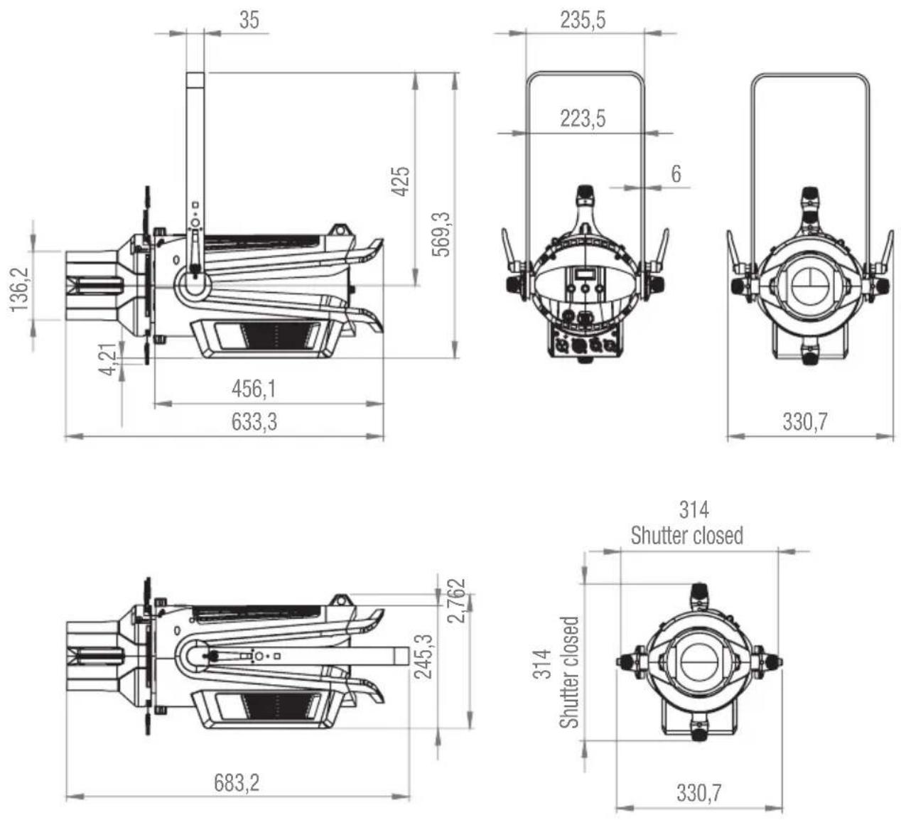
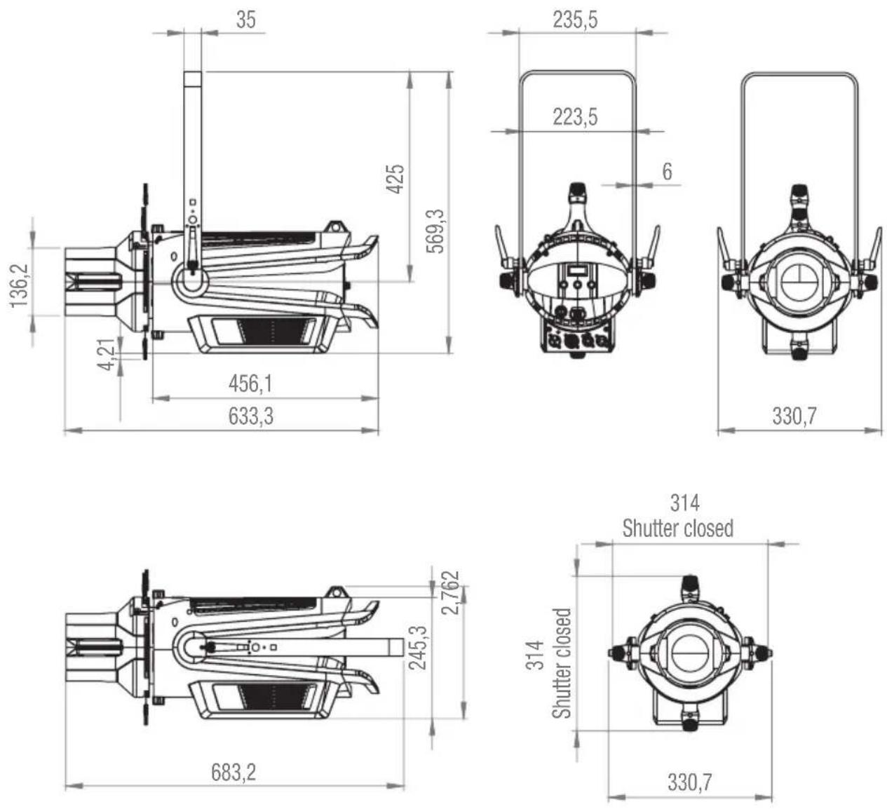
| Dimensions (L × W × H) | 633.3 × 330.7 × 314 mm |
| Weight (with lens holder) | 8.9 kg |
| Protection rating | IP20 (indoor) |
| Cooling | Forced convection, silent fan, fan-off mode |
| Operating temperature | -10 °C to 45 °C |
| Minimum distance to illuminated surface | 0.5 m |
| Minimum distance to flammable materials | 0.2 m |
| Fuse | 250 V T6.3 A (5 × 20 mm) |
| Connections | Power In/Out TRUE1, DMX 5-pin, iDMX slot |
| Protection class | Class I |
| Included accessories | Soft edge filter, network cable |
Frequently Asked Questions - P2 T Cameo
User questions about P2 T Cameo
0 question about this device. Answer the ones you know or ask your own.
Ask a new question about this device
Download the instructions for your Lamp in PDF format for free! Find your manual P2 T - Cameo and take your electronic device back in hand. On this page are published all the documents necessary for the use of your device. P2 T by Cameo.
USER MANUAL P2 T Cameo
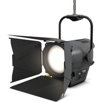
natural_image
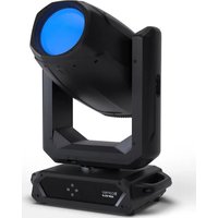
Two black professional spotlights with adjustable armrests and focused lenses, displayed against a white background (no text or symbols visible)P2 T
TUNGSTEN PROFILE SPOTLIGHT
CLP2T
P2 D
DAYLIGHT PROFILE SPOTLIGHT
CLP2D
CONTENTS / INHALTSVERZEICHNIS / CONTENU / CONTENIDO / TREŚĆ / CONTENUTO
ENGLISH
INFORMATION ON THIS USER MANUAL 6
INTENDED USE 6
DEFINITIONS AND SYMBOL EXPLANATIONS 6
SAFETY INSTRUCTIONS 7
NOTES FOR MOBILE INDOOR DEVICES 10
INCLUDED 10
INTRODUCTION 11
CONNECTIONS, OPERATING AND DISPLAY ELEMENTS 12
OPERATION 14
INSTALLATION 19
INSTALL FIXED BEAM ANGLE LENS TUBE 20
CARE, MAINTENANCE AND REPAIR 23
OPTIONAL ACCESSORIES 24
TECHNICAL DATA 26
MINIMUM DISTANCE TO ILLUMINATED SURFACE 28
MINIMUM DISTANCE TO NORMALLY FLAMMABLE MATERIALS 28
DISPOSAL 29
MANUFACTURER'S DECLARATIONS 29
DEUTSCH
This device has been developed and manufactured to the highest quality standards to ensure many years of problem-free operation. Please read this user manual carefully to be able to use your new Cameo product quickly and optimally. Further information about Cameo Light is available on our website CAMEOLIGHT.COM.
INFORMATION ON THIS USER MANUAL
- Carefully read the safety instructions and the entire manual before operating the device.
- Observe the warnings on the device and in the user manual.
• Always keep the user manual within reach. - If you sell or pass on the device, it is important that you also include this user manual, as it is an integral part of the product.
INTENDED USE
The product is a device for event technology!
This product has been developed for professional use in the field of event technology and is not suitable for use as domestic lighting!
Furthermore, this product is only intended for qualified users with specialist knowledge of event technology!
Use of the product outside the specified technical data and operating conditions is considered inappropriate!
Liability for damage and third-party damage to persons and property due to inappropriate use is excluded!
The product is not suitable for:
- Use by persons (including children) with limited physical, sensory or mental abilities or lack of experience and knowledge.
- Children (children must be instructed not to play with the device).
DEFINITIONS AND SYMBOL EXPLANATIONS
- HAZARD: The word HAZARD, possibly in combination with a symbol, indicates situations in which there is an immediate danger or risk of potentially fatal injury.
- WARNING: The word WARNING, possibly in combination with a symbol, indicates situations in which there is an immediate danger or risk of potentially fatal injury.
- CAUTION: The word CAUTION, possibly in combination with a symbol, indicates situations or conditions that could result in injury.
- ATTENTION: The word ATTENTION, possibly in combination with a symbol, indicates situations or conditions that could result in damage to property and/or the environment.
This symbol identifies hazards that can cause electric shock.

This symbol identifies hazardous areas or hazardous situations.
This symbol indicates hazards caused by hot surfaces.

This symbol indicates hazards caused by intense light sources.

This symbol indicates a device in which there are no user-replaceable parts.

This symbol indicates additional information on the operation of the product.
SAFETY INSTRUCTIONS

HAZARD:
- Do not open the device and do not perform any modifications.
- If your device no longer functions properly, if liquids or objects get inside it or if it has been damaged in any other way, switch it off immediately and unplug it from the power source. The device may be repaired only by authorised repair technicians.
- For devices of protection class 1, the protective conductor must be connected correctly. Never disconnect the protective conductor. Devices of protection class 2 do not have a protective conductor.
- Ensure that live cables are not kinked or otherwise mechanically damaged.
- Never bypass the device fuse.

WARNING:
- The device may not be operated if it shows obvious signs of damage.
- The device may only be installed in a voltage-free state.
- If the device's power cable is damaged, the device may not be used.
- Permanently connected power cables may only be replaced by a qualified person.
ATTENTION:
- Do not switch on the device if it has been exposed to extreme temperature fluctuations (for example, following transport). Moisture and condensation can damage the device. Switch on the device only when it has reached room temperature.
- Ensure that the voltage and frequency of the mains supply match the values specified on the device. If the device has a voltage selector switch, do not connect the device until it has been set correctly. Use only suitable power cables.
- To disconnect the device from the mains on all poles, it is not sufficient to press the on/off switch on the device.
- Make sure that the fuse used corresponds to the type printed on the device.
- Ensure that suitable measures have been taken against overvoltage (e.g. lightning strikes).
- Observe the specified maximum output current on devices with a Power Out connection. Ensure that the total current consumption of all connected devices does not exceed the specified value.
- Replace plug-in power cables with original cables only.

HAZARD:
- Choking hazard! Plastic bags and small parts must be kept out of reach of persons (including children) with reduced physical, sensory or mental capabilities.
- Risk of falling! Make sure that the device is securely installed and will not fall down. Only use suitable stands or mounts (particularly for fixed installations). Ensure that accessories are properly installed and secured. Ensure that applicable safety regulations are observed.

WARNING:
- Use the device in the prescribed manner only.
- Operate the device using only accessories of the type recommended and supplied by the manufacturer.
- Observe safety regulations applicable in your country during installation.
- After connecting the device, ensure that all cables are routed so as to avoid damage or accidents, such as from tripping.
- Always observe the specified minimum distance to normally flammable materials! Unless explicitly stated, the minimum distance is 0.3 m.

CAUTION:
- Moving components such as mounting brackets may become jammed.
- In the case of devices with motor-driven components, there is a risk of injury due to the movement of the device. Sudden movement of the device can cause shock reactions.
- The housing surface of the device can become very hot during regular operation. Ensure that accidental touching of the housing is not possible. Always allow the device to cool sufficiently before removal, maintenance work and charging etc.

ATTENTION:
- Do not install or use the device in the vicinity of radiators, accumulators, stoves, or other heat sources. Ensure that the device is always installed in such a way that it is sufficiently cooled and cannot overheat.
- Do not place any ignition sources, such as burning candles, near the device.
- Ventilation openings must not be covered and fans must not be blocked.
- For transport, use the original packaging or packaging provided by the manufacturer.
- Avoid any impacts to or shaking of the device.
- Observe the IP rating and the ambient conditions such as temperature and humidity according to the specifications.
- Devices can be continuously further developed. In the event of deviating information on operating conditions, performance or other device properties between the user manual and the device labelling, the information on the device always has priority.
- The device is not suitable for tropical climate zones or for operation over 2,000 m above sea level.
- Unless explicitly stated, the device is not suitable for operation under marine conditions.

PLEASE NOTE:
For conversion or retrofit sets or accessories provided by the manufacturer, it is essential to observe the instructions included.
CAUTION! IMPORTANT INFORMATION REGARDING LIGHTING PRODUCTS!

- Never look directly into the beam of light, not even for a short period of time.
- Never look into the beam of light using optical devices such as a magnifying glass.
- Stroboscopic effects may cause epileptic seizures in susceptible individuals!

- Permanently installed lamps are built into these lighting units. These may not be replaced by the user. The lamps contained in this lighting unit may only be replaced by the manufacturer, its service partner, or a similarly qualified person.
NOTES FOR MOBILE INDOOR DEVICES

- Temporary operation! Event equipment is generally only designed for temporary operation.
- Continuous operation or permanent installation can impair the functioning of the device and cause premature ageing.
INCLUDED
Remove the product from the packaging and remove all packaging material.
Please check the completeness and integrity of the delivery and notify your distribution partner immediately after purchase if the delivery is not complete or if it is damaged.
Included with the CLP2T:
▶ 1 x CLP2 tungsten profile spotlight (without lens tube)
▶ 1 x soft edge filter
1x power cable
▶ User manual
Included with the CLP2D:
▶ 1 x CLP2 daylight profile spotlight (without lens tube)
▶ 1 x soft edge filter
1x power cable
▶ User manual
A lens tube is NOT included with the spotlight. Tubes with lenses of different beam angles are available separately. Do NOT operate the spotlight without the lens tube!
INTRODUCTION
Tungsten profile spotlight
CLP2T
Daylight profile spotlight
CLP2D
CONTROL FUNCTIONS:
1CH, 2CH 16-bit, 2CH strobe, 3CH device, 4CH, 5CH DMX control
Master/slave operation
Standalone operation
W-DMX™ (with optional iDMX stick, product number CLIDMXSTICK)
FEATURES:
230 W tungsten/daylight COB LED. DMX512. W-DMX™ optional. 5-pin DMX connections. Quick-light via rotary-push encoder. Operating voltage: 100–240 V AC.
The spotlight features the RDM standard (Remote Device Management). Remote device management allows the user to view the status and configuration of RDM terminals via an RDM-capable controller.
Cameo UNICON also provides access to the entire spotlight menu.
CONNECTIONS, OPERATING AND DISPLAY ELEMENTS
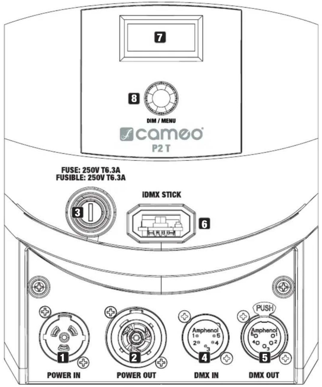
- The CLP2T and CLP2D models feature identical connections, operating and display elements -
1 POWER IN
TRUE1-compatible mains input socket. Operating voltage 100–240 V AC/50–60 Hz. A suitable power cable with a TRUE1-compatible plug is included.
2 POWER OUT
TRUE1-compatible mains output socket. Facilitates power supply to other CAMEO spotlights. Ensure that the total power consumption of all devices connected to the device does not exceed the given ampere (A) value.
3 FUSE
Fuse holder for 5 x 20 mm fuses. IMPORTANT: Replace the fuse only with a fuse of the same type and value. In the event of repeated fuse failure, please contact an authorised service centre.
4 DMX IN
Male 5-pin XLR socket for connection to a DMX control device (e.g. DMX console).
5 DMX OUT
Female 5-pin XLR socket for sending the DMX control signal.
6 IDMX STICK
Connection for the optional iDMX stick for W-DMX ^TM connection (plug in the iDMX stick with the antenna facing upwards).
7 OLED DISPLAY
The OLED display shows the currently activated mode (main display), the menu items in the menu and the numerical value or operational status in certain menu items. If there is no input for around two minutes, the display automatically returns to the main display. Note regarding the main display in operating modes with external control: As soon as the control signal is interrupted, the characters in the display begin to flash. When there is a control signal again, the flashing stops.
8 DIM / MENU
DIM – If one of the DMX modes is enabled and there is no DMX signal to the device, the encoder serves as master dimmer control and you can set the brightness of the spotlight with values from 000 to 255 by turning the encoder (Quicklight).
MENU – Push the encoder to access the main menu and select menu items by turning the encoder. Press the encoder to enter a submenu, change values and status by turning the encoder and confirm the changes by pressing the encoder.
OPERATION
NOTES
- As soon as the spotlight is correctly connected to the power supply, the following will be displayed in succession: "Welcome to Cameo", the model name and the software version. After this process, the lamp is ready for operation and starts in the previously enabled mode.
- If one of the DMX modes or slave mode is enabled and there is no control signal at the DMX input, the characters in the centre lines of the display will start to flash.
- If no input is made within approximately 1 minute, the currently activated mode is automatically shown in the display (main display).
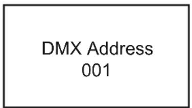
MAIN DISPLAY DMX MODE
The main display shows the currently activated mode (in the example, DMX mode with DMX start address 001).
DMX Address 001
SETTING DMX START ADDRESS (DMX address)
Press the encoder to access the main menu. Rotate the encoder to select the menu item DMX Address (left arrow) and confirm by pushing the encoder. You can now configure the DMX start address as required by rotating the encoder (the highest value depends on the selected DMX mode). Confirm the entry by pushing the encoder. Select the arrow symbol at the top of the menu for "back" and push the encoder to return to the main display. DMX mode is automatically activated when setting the DMX start address.


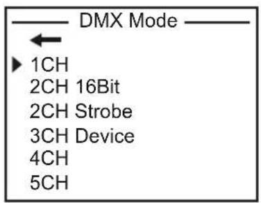
CONFIGURING DMX MODE (DMX Mode)
Press the encoder to access the main menu. Rotate the encoder to select the menu item DMX Mode (observe left selection arrow) and confirm by pushing the encoder. You can now select the desired DMX mode by rotating the encoder. Confirm the selection by pushing the encoder. Select the arrow symbol at the top of the menu for "back" and push the encoder to return to the main display. Tables with the channel assignment of the different DMX modes can be found in these instructions under DMX CONTROL.


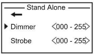
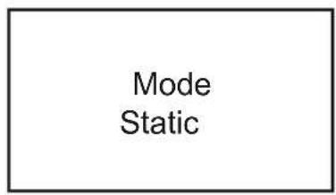
STAND ALONE MODE (Stand Alone)
Press the encoder to access the main menu. Rotate the encoder to select the menu item Stand Alone (oberve left selection arrow) and confirm by pushing the encoder. Now select the submenu item Dimmer and confirm by pushing the encoder and rotate the encoder to set the desired brightness with values between 000 (blackout) and 255 (maximum brightness). Confirm your entry by pressing the encoder. A stroboscopic effect can now be activated as required and set in the same way (strobe value 000 = strobe off. Value 001 = lowest flash frequency. Value 255 = highest flash frequency). Now select the arrow symbol for "back" at the top of the submenu. Push the encoder and access the main menu in the same way to return to the main display.

SLAVE MODE
Press the encoder to access the main menu. Rotate the encoder to select the menu item Slave (observe left selection arrow) and confirm by pushing the encoder. Slave mode is now enabled, and the main display is automatically displayed. Connect the slave and master unit (same model, same software version) using a DMX cable, and activate stand alone mode on the master unit. The slave unit will now follow the master unit.


DEVICE SETTINGS (Settings)
Press the encoder to access the main menu. Rotate the encoder to select the menu item Settings (observe left selection arrow) and confirm by pushing the encoder. This will take you to the submenu for setting the submenu items (see table, rotate the encoder to select, push the encoder to confirm selection). Now select the arrow symbol for "back" at the top of the submenu. Push the encoder and access the main menu in the same way to return to the main display.

| Settings | |||||
| ← | Back | ||||
| Wireless Settings | = | Configure wireless control (IDMX stick optionally available) | ← | Back | |
| WDMX State | ← | Back | |||
| On Wireless control enabled | |||||
| Off Wireless control disabled | |||||
| Signal routing | ← | Back | |||
| Receive only W-DMX reception only | |||||
| To XLR Signal -> DMX OUT | |||||
| Backup by XLR | Backup via DMX IN with W-DMX signal interruption | ||||
| Display Off Timer | = Display lighting Back | ← | |
| Always On permanently on | |||
| Off after 20 s | Deactivates after approximately 20 seconds of inactivity | ||
| DMX Fail | = Operational status with DMX signal fault | ← | Back |
| Hold Last command is retained | |||
| Blackout activates blackout | |||
| Full On Spotlight switches to full on | |||
| Stand Alone | Spotlight switches to stand-alone mode with the last selected settings | ||
| Dimmer Curve | = Dimmer curve | ← | Back |
| Linear Light intensity increases linearly with DMX value | |||
| Exponential Light intensity can be finely adjusted at lower DMX values and broadly adjusted at higher DMX values | |||
| Logarithmic | Light intensity can be broadly adjusted at lower DMX values and finely adjusted at higher DMX values | ||
| S-curve Light intensity can be finely adjusted at lower and higher DMX values and broadly adjusted at medium DMX values | |||
| Dimmer Response | = Dimmer response | ← | Back |
| LED Light responds abruptly to changes in DMX value | |||
| Halogen Light behaves like a halogen spotlight with slight brightness changes | |||
| PWM Frequency | = LED PWM frequency | ← | Back |
| 800 Hz1200 Hz2000 Hz3600 Hz12 kHz18.9 kHz25 kHz | Configuration of LED PWM frequency | ||
| Fan = Adjust fan control Back | ← | |||
| Auto Automatic fan control | ||||
| Off Deactivated fan with greatly reduced brightness | ||||
| Constant Low | Constantly low fan speed with reduced brightness, if necessary | |||
| Constant Mid | Constant average fan speed with reduced brightness, if necessary | |||
| Constant High | Constant high fan speed | |||
| Factory Reset | = | Reset to factory setting | ← | Back |
| Reset Now! | Restore factory settings | |||
Dimmer curves


line
| DMX value | Light intensity | | --------- | --------------- | | 0 | 0 | | 1 | 0.5 | | 2 | 1 | | 3 | 1.5 | | 4 | 2 | | 5 | 2.5 | | 6 | 3 | | 7 | 3.5 | | 8 | 4 | | 9 | 4.5 | | 10 | 5 | | 11 | 5.5 | | 12 | 6 | | 13 | 6.5 | | 14 | 7 | | 15 | 7.5 | | 16 | 8 | | 17 | 8.5 | | 18 | 9 | | 19 | 9.5 | | 20 | 10 |
line
| DMX value | Light intensity | | --------- | --------------- | | 0 | 0 | | 1 | 0.5 | | 2 | 1 | | 3 | 1.5 | | 4 | 2 | | 5 | 2.5 | | 6 | 3 | | 7 | 3.5 | | 8 | 4 | | 9 | 4.5 | | 10 | 5 | | 11 | 5.5 | | 12 | 6 | | 13 | 6.5 | | 14 | 7 | | 15 | 7.5 | | 16 | 8 | | 17 | 8.5 | | 18 | 9 | | 19 | 9.5 | | 20 | 10 |SYSTEM INFORMATION (System Info)
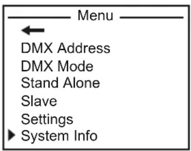
Get information on device firmware, LED unit temperature and operating time. Press the encoder to access the main menu. Rotate the encoder to select the menu item System info (observe left selection arrow) and confirm by pushing the encoder. This will take you to the submenu for selecting the submenu items (see table, rotate the encoder to select, push the encoder to confirm selection). Now select the arrow symbol for "back" at the top of the submenu. Push the encoder and access the main menu in the same way to return to the main display.
| System Info | ||||
| ← | Back | |||
| Firmware = Displays | displays | device firmware | Main CPU Vx.xx | |
| Temperature = | Displays | temperature of LED unit | ← | Back |
| LED xx °C / | xx °F | |||
| Unit °C (= display in degrees Celsius) | ||||
| Operation Hours | = | Displays operating time | xx:xx h Displ | lays total operating time in hours and minutes |
INSTALLATION

HAZARD: Overhead mounting requires extensive experience, including the calculation of the load limit values of the installation material and regular safety inspection of all installation materials and spotlights. If you do not have these qualifications, do not attempt to perform an installation yourself. Refer instead to a qualified professional. There is a risk of incorrectly mounted and secured devices coming loose and falling down. This can cause serious injury or death.
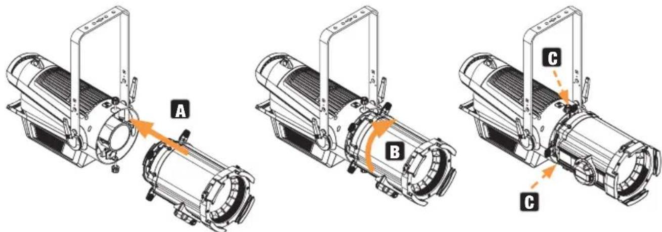
The mounting bracket can be attached to the spotlight in two positions (A and B). When changing the position, make sure that the mounting bracket is reattached securely to the spotlight in the same way.
Installation on a T-bar is possible with a suitable traverse clamp, which is attached to the mounting bracket (C). Suitable truss clamps are optionally available. Loosen the two clamp levers on the sides of the spotlight (D) to adjust the beam direction in the vertical plane and tighten the two clamp levers again after adjustment.
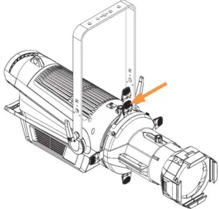
The securing lug for securing the spotlight is located on the top of the housing (E).

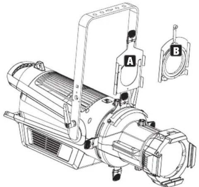
INSTALL FIXED BEAM ANGLE LENS TUBE PLEASE NOTE:
- Do not operate the spotlight during the installation or removal of a lens tube.
- Be careful not to damage or contaminate the lens when installing or removing a lens tube. Ensure that no foreign bodies enter the spotlight housing.
- Do not operate the spotlight without the lens tube.
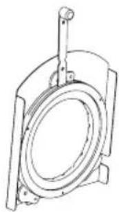
To mount a fixed beam angle lens tube, slide the lens tube with the spring-loaded filter frame hinge upwards into the tube with the diaphragm slider unit (A). Now turn the two supplied knurled screws (B) into the corresponding threads in the lens tube and tighten them. To focus the light projection, loosen the knurled screws slightly and move the lens tube in its guide as desired. Tighten the knurled screws again after focusing.

REMOVAL OF TUBE WITH DIAPHRAGM SLIDER UNIT PLEASE NOTE:
- Do not operate the spotlight during the installation or removal of a tube.
- Be careful not to damage or contaminate the lens behind when disassembling or assembling the tube. Ensure that no foreign bodies enter the spotlight housing.
- Do not operate the spotlight without the tube.
To remove the tube, first loosen the two knurled screws on the top and bottom of the spotlight housing (A). Now turn the tube approximately one eighth of a turn counterclockwise (B) and remove it from the spotlight housing (C) towards the front. To install the tube, proceed in reverse order, making sure that the unit is correctly seated in the corresponding guides in the spotlight housing.

INSTALL ZOOM LENS TUBE WITH DIAPHRAGM SLIDER
PLEASE NOTE:
- Do not operate the spotlight during the assembly or disassembly of the zoom lens tube.
- Be careful not to damage or contaminate the lens behind when disassembling or assembling the zoom lens tube. Ensure that no foreign bodies enter the spotlight housing.
- Do not operate the spotlight without the zoom lens tube.
Disassemble the tube with the diaphragm slider unit as described above. Place the zoom lens tube approximately one eighth of a turn counterclockwise onto the front of the spotlight housing (A). Now turn the zoom lens tube clockwise about an eighth of a turn, making sure that the spring-loaded locking bracket for a filter frame is facing upwards and that the unit is correctly seated in the corresponding guides in the spotlight housing (B). Now lock the zoom lens tube in place using the previously loosened knurled screws on the top and bottom of the spotlight housing (C).
SOFT EDGE FILTER
The soft edge filter for light projection with soft and homogeneous edges is located in front of the upper shutter as standard. Leave the soft edge filter in place during operation.
natural_image
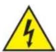
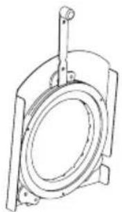
Technical line drawing of an industrial machine with mounting bracket and internal components (no text or symbols)GOBO HOLDER AND IRIS
The tube with framing unit and the zoom tubes have a built-in bay for insertion of a gobo holder (A) or an iris module (B) (gobo holder and iris module optionally available). To do so, slightly loosen the two knurled screws of the shaft cover (C) and push the cover towards the front of the spotlight. Now insert the gobo holder or iris module into the installation bay as far as it will go. A spring clip holds the accessory in place. Now push the shaft cover back over the installation bay as far as it will go and secure it with the two knurled screws.
natural_image
Technical line drawing of a mechanical device with labeled parts A and B (no text or symbols beyond labels)
CARE, MAINTENANCE AND REPAIR
In order to ensure the long-term, proper functioning of the device, it must be regularly cleaned and, if necessary, maintained. The maintenance requirement depends on the intensity of use and the environment in which it is used.
We generally recommend a visual inspection before each operation. Furthermore, we recommend carrying out all the applicable maintenance measures specified below once every 500 operating hours or, in the case of a lower intensity of use, at the latest after one year. Warranty claims may be limited in the event of defects resulting from inadequate maintenance.
CARE (carried out by user)
WARNING! Before carrying out any maintenance work, the power supply and, if possible, all device connections must be unplugged.

PLEASE NOTE! Improper care can lead to impairment of the device or even destruction.
- Housing surfaces must be cleaned with a clean, damp cloth. Make sure that no moisture can penetrate the device.
- Air inlets and outlets must be regularly cleaned of dust and dirt. If compressed air is used, make sure that damage to the device is prevented (e.g. fans must be blocked in this case).
- Lines and plug contacts must be cleaned regularly and dust and dirt must be removed.
- In general, no cleaning agents or abrasive agents may be used, otherwise the surface finish may be damaged.
- Devices must generally be stored dry and protected from dust and dirt.
MAINTENANCE AND REPAIR (by qualified personnel only)
HAZARD! There are live components in the device. Even after disconnecting the mains connection, there may still be residual voltage in the device, e.g. due to charged capacitors.

PLEASE NOTE! There are no user-serviceable components in the device.

PLEASE NOTE! Maintenance and repair work may only be carried out by qualified specialist personnel authorised by the manufacturer. If in doubt, consult the manufacturer.

PLEASE NOTE! Improperly performed maintenance work may affect warranty claims.
OPTIONAL ACCESSORIES
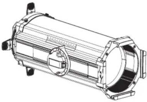
CLP21530LENS
Zoom lens tube with 15^ to 30^ beam angle diaphragm slider unit and soft edge filter included
natural_image
Technical line drawing of a cylindrical mechanical component with mounting flanges and internal components (no text or symbols)CLP219LENS
Lens tube with 19^ beam angle
CLP226LENS
Lens tube with 26^ beam angle
CLP236LENS
Lens tube with 36^ beam angle
CLP250LENS
Lens tube with 50° beam angle
CLPGHOLDER
Gobo holder

natural_image
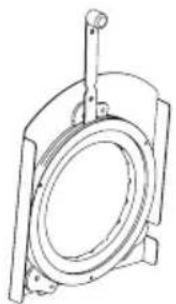
Line drawing of a mechanical component with a circular opening and protruding rod (no text or symbols)CLP22550LENS
Zoom lens tube with 25^ to 50^ beam angle diaphragm slider unit and soft edge filter included

natural_image
Technical line drawing of a mechanical assembly with no visible text or symbols
natural_image
Technical line drawing of a mechanical component with no visible text or symbolsCLP2IRIS
Adjustable iris
natural_image
Technical line drawing of a mechanical component with a cylindrical housing and mounting base (no text or symbols)DIMENSIONS
TECHNICAL DATA
| ITEM NUMBER: CLP2D CLP2T | ||
| Product category Static LED Light Static LED Light | ||
| Type Ellipsoidal (Profiler) Ellipsoidal (Profiler) | ||
| Light source 230 W Daylight COB LED with fixed CT | 230 W Warm white COB LED with fixed CT | |
| Luminous Flux Light engine: 15201lm | Light engine: 13984lm | |
| 19° lens: 11364lm | 19° lens: 10633lm | |
| 26° lens: 13844lm | 26° lens: 12644lm | |
| 36° lens: 13940lm | 36° lens: 12811lm | |
| 50° lens: 12753lm | 50° lens: 11687lm | |
| 15°-30° lens@15°: 8543lm | 15°-30° lens@15°: 8085lm | |
| 15°-30° lens@30°: 12941lm | 15°-30° lens@30°: 12230lm | |
| 25°-50° lens@25°: 13947lm | 25°-50° lens@25°: 12527lm | |
| 25°-50° lens@50°: 14193lm | 25°-50° lens@50°: 12758lm | |
| Lense / Optic (optional) fixed lens: 19°; 26°;36°; 50°; manual zoom: 15°-30°;25°-50° | (optional) fixed lens: 19°; 26°;36°; 50°; manual zoom: 15°-30°;25°-50° | |
| PWM frequency 800 Hz; 1200 Hz; 2000 Hz;3600 Hz; 12 kHz; 18.9 kHz;25 kHz | 800 Hz; 1200 Hz; 2000 Hz;3600 Hz; 12 kHz; 18.9 kHz;25 kHz | |
| Dimmer resolution 16bit 16bit | ||
| Dimmer curves | Linear; Exponential; Logarithmic;S-Curve | Linear; Exponential; Logarithmic;S-Curve |
| Halogen simulation | LED response; Halogen response | LED response; Halogen response |
| Strobe | 0 Hz–20 Hz | 0 Hz–20 Hz |
| LED colours / colour temperature | 5517K fixed CT | 3266K fixed CT |
| CRI | >94 | >97 |
| Beam angle | Beam angle with optional lens:19°; 26°; 36°; 50°; 15°–30°;25°–50° | Beam angle with optional lens:19°; 26°; 36°; 50°; 15°–30°;25°–50° |
| Focus operation | Manual focus operation | Manual focus operation |
| CCT | 5517K (nominal 5600K) | 3266K (nominal 3200K) |
| Framing system | Manual Framing Blades | Manual Framing Blades |
| Control protocols | DMX, RDM, Unicon Remote;Optional W-DMX with IDMX Stick,EZ Remote | DMX, RDM, Unicon Remote;Optional W-DMX with IDMX Stick,EZ Remote |
| Data connections | XLR 5-pin In/Out; I-DMX Slot | XLR 5-pin In/Out; I-DMX Slot |
| DMX modes 1CH Dim; 2CH 16bit; 2CH Strobe;3CH Device; 4CH Device; 5CH Full | 1CH Dim; 2CH 16bit; 2CH Strobe;3CH Device; 4CH Device; 5CH Full | |
| DMX functions Dimmer; Dimmer fine; Strobe;Device Settings (simple); DimmerCurve; Device Settings (full) | Dimmer; Dimmer fine; Strobe;Device Settings (simple); DimmerCurve; Device Settings (full) | |
| RDM functions Cameo RDM Standard Cameo RDM Standard | ||
| Stand-Alone Encoder Mode Dim Strobe; Slave Encoder Mode Dim Strobe; Slave | ||
| System Settings DMX Address; DMX-Mode;Stand-Alone; Slave; WirelessSettings; Display Off Timer;DMX Fail; Dimmer Curve; DimmerResponse; LED Frequency; Fan;Factory Reset; | DMX Address; DMX-Mode;Stand-Alone; Slave; WirelessSettings; Display Off Timer;DMX Fail; Dimmer Curve; DimmerResponse; LED Frequency; Fan;Factory Reset; | |
| User Interface 1 x Push and turn encoder 1 x Push and turn encoder | ||
| Display / Indicators OLED display OLED display | ||
| IP-Rating IP 20 indoor use | IP 20 indoor use | |
| Ambient Temperature Rating | -10°–45°C | -10°–45°C |
| Humidity Rating | <80% non condensing | <80% non condensing |
| Cooling System | Forced convection with silent fan;Fan Off operation | Forced convection with silent fan;Fan Off operation |
| Noise Level | 32.4 dB @ Auto Fan Mode 32.4 dB @ Auto Fan Mode | |
| Operation Voltage | 100 V AC–240 V AC /50 Hz–60 Hz | 100 V AC–240 V AC /50 Hz–60 Hz |
| Max. Current | 1.08 A @ 230 V; 1,95 A @ 110 V | 1.08 A @ 230 V; 1,95 A @ 110 V |
| Max. Output Current | 12 A | 12 A |
| Max. power consumption | 219 W @ 230 V; 222 W @ 110 V | 219 W @ 230 V; 222 W @ 110 V |
| Standby power | 42 W | 42 W |
| Fuse | T 6.3 AL 250 V | T 6.3 AL 250 V |
| Power Connection | True 1 compatible In/Out | True 1 compatible In/Out |
| Power-Link | 8 units @230 V; 4 units @ 110 V | 8 units @230 V; 4 units @ 110 V |
| Protection Class | Protection Class 1 | Protection Class 1 |
| Housing | Die Cast Magnesium Alloy, black powder coated | Die Cast Magnesium Alloy, black powder coated |
| Minimum distance to illuminated surface | 0.5 m | 0.5 m |
Minimum distance to normally flammable materials 0.2 m 0.2 m
Dimensions 633.3 mm x 330.7 mm x 314 mm 633.3 mm x 330.7 mm x 314 mm (L x W x H)
| Weight Engine and lens holder(as shipped): 8.9 kgLight engine: 7.3 kgLens holder: 1.6 kg19° lens: 1.5 kg26° lens: 1.46 kg36° lens: 1.35 kg50° lens: 1.35 kg15° – 30° lens: 5.8 kg25° – 50° lens: 4.5 kg | Engine and lens holder(as shipped): 8.9 kgLight engine: 7.3 kgLens holder: 1.6 kg19° lens: 1.5 kg26° lens: 1.46 kg36° lens: 1.35 kg50° lens: 1.35 kg15° – 30° lens: 5.8 kg25° – 50° lens: 4.5kg |
RDM UID 0x08A4011B (0000-FFFF) 0x08A4011A (0000-FFFF)
MINIMUM DISTANCE TO ILLUMINATED SURFACE

This symbol with distance specification in metres (m) indicates the minimum distance between the light head and the illuminated surface. In this example, the distance is 0.5 m. The value applicable for this unit can be found in the technical data in this manual and the imprint on the unit housing!
MINIMUM DISTANCE TO NORMALLY FLAMMABLE MATERIALS

This symbol with distance specification in metres (m) indicates the minimum distance between the light head and normally flammable materials. In this example, the distance is 0.5 m. The value applicable for this unit can be found in the technical data in this manual!
DISPOSAL

Packaging:
- Packaging can be fed into the reusable material cycle using the usual disposal methods.
- Please separate the packaging in accordance with the disposal laws and recycling regulations in your country.
Device:
- This device is subject to the European Directive on Waste Electrical and Electronic Equipment, as amended. WEEE Directive Waste Electrical and Electronic Equipment. Old appliances do not belong in household waste. The old device must be disposed of via an approved disposal company or a municipal disposal facility. Please observe the applicable regulations in your country!
- Observe all disposal laws applicable in your country.
- As a private customer, you can obtain information on environmentally-friendly disposal options from the seller of the product or the appropriate regional authorities.

Batteries:
- Batteries should not be disposed of in household waste. Batteries must be disposed of via an approved disposal company or a municipal disposal facility.
- Observe all disposal laws and regulations applicable in your country.
- As a private customer, you can obtain information on environmentally-friendly disposal options from the seller of the product or the appropriate regional authorities.
- Devices with batteries that cannot be removed by the user must be taken to a collection point for electrical devices.
MANUFACTURER'S DECLARATIONS
MANUFACTURER'S WARRANTY & LIMITATION OF LIABILITY
Adam Hall GmbH, Adam-Hall-Str. 1, 61267 Neu Anspach, Germany / E-mail Info@adamhall.com / +49 (0)6081 / 9419-0.
Our current warranty conditions and limitation of liability can be found at:
https://cdn-shop.adamhall.com/media/pdf/Manufacturers-Declarations-CAMEO DE EN ES FR.pdf.
Contact your distribution partner for service.
UKCA- CONFORMITY
Hereby, Adam Hall Ltd. declares that this product meets the following guidelines (where applicable)
Electrical Equipment (Safety) Regulations 2016
Electromagnetic Compatibility Regulations 2016 (SI 2016/1091)
The Restriction of the Use of Certain Hazardous Substances in Electrical and Electronic Equipment Regulation 2012 (SI 2012/3032)
Radio Equipment Regulations 2017(SI 2016/2015)
UKCA- DECLARATION OF CONFORMITY
Products that are subject to Electrical Equipment(Safety)Regulation 2016, EMC Regulation 2016 or RoHS Regulation can be requested at info@adamhall.com.
Products that are subject to the Radio Equipments Regulations 2017 (SI2017/1206) can be downloaded from www.adamhall.com/compliance/
FCC STATEMENT
This equipment has been tested and found to comply with the limits for a Class B digital device, pursuant to part 15 of the FCC Rules. These limits are designed to provide reasonable protection against harmful interference in a residential installation. This equipment generates, uses and can radiate radio frequency energy and, if not installed and used in accordance with the instructions, may cause harmful interference to radio communications. However, there is no guarantee that interference will not occur in a particular installation. If this equipment does cause harmful interference to radio or television reception, which can be determined by turning the equipment off and on, the user is encouraged to try to correct the interference by one or more of the following measures:
- Reorient or relocate the receiving antenna.
- Increase the separation between the equipment and receiver.
- Connect the equipment into an outlet on a circuit different from that to which the receiver is connected.
- Consult the dealer or an experienced radio/TV technician for help.
Caution: Any changes or modifications to this device not explicitly approved by manufacturer could void your authority to operate this equipment.
This device complies with part 15 of the FCC Rules. Operation is subject to the following two conditions: (1) This device may not cause harmful interference, and (2) this device must accept any interference received, including interference that may cause undesired operation.
RF EXPOSURE INFORMATION
This equipment complies with FCC radiation exposure limits set forth for an uncontrolled environment. This equipment should be installed and operated with minimum distance 20cm between the radiator and your body.
SUBJECT TO MISPRINTS AND ERRORS, AS WELL AS TECHNICAL OR OTHER MODIFICATIONS!
DEUTSCH
SLAVE-BETRIEB
LINSENTUBUS MIT FIXEM ABSTRAHLWINKEL MONTIEREN HINWEISE:
natural_image
Technical line drawing of an industrial machine with a highlighted component (no text or symbols)GOBOHALTER UND IRIS
natural_image
Technical line drawing of a mechanical device with labeled parts A and B (no text or symbols beyond labels)
natural_image
Technical line drawing of a cylindrical mechanical component with mounting flanges and internal cavities (no text or symbols)CLP219LENS
natural_image
Technical line drawing of a target with an oval opening and a circular hole, no text or symbols presentCLP22550LENS
natural_image
Technical line drawing of a mechanical assembly (no text or symbols visible)
natural_image
Technical line drawing of a mechanical component with no visible text or symbolsCLP2IRIS
Verstellbare Iris

natural_image
Technical line drawing of a mechanical component with a cylindrical housing and mounting bracket (no text or symbols)ABMESSUNGEN

TECHNISCHE DATEN
https://cdn-shop.adamhall.com/media/pdf/Manufacturers-Declarations-CAMEO_DE_EN_ES_FR.pdf.
flowchart
graph TD
    A["001"] --> B["512"]
    B --> C["DMX Address 001"]
RÉGLAGE DU MODE DE FONCTIONNEMENT DMX (DMX Mode)
MODE SLAVE
MONTER UN TUBE DE LENTILLE AVEC UN ANGLE DE RAYONNEMENT FIXE REMARQUES :
DÉMONTER LE TUBE AVEC L'UNITÉ COULISSANTE DE DIAPHRAGME REMARQUES :
natural_image
Technical line drawing of a mechanical device with no visible text or symbolsnatural_image
Technical line drawing of an industrial lamp or optical instrument with labeled components A and B (no text or symbols beyond labels)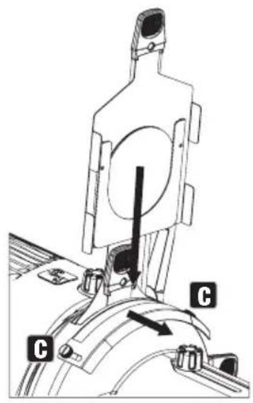
ENTRETIEN, MAINTENANCE ET RÉPARATION
natural_image
Technical line drawing of a cylindrical mechanical component with mounting flanges and internal components (no text or symbols)CLP219LENS
natural_image
Technical line drawing of a mechanical component with no visible text or symbolsCLP22550LENS
natural_image
Technical line drawing of a mechanical assembly with no visible text or symbols
natural_image
Technical line drawing of a mechanical component with no visible text or symbolsCLP2IRIS
Iris réglable
natural_image
Technical line drawing of a mechanical component with a cylindrical housing and mounting base (no text or symbols)DIMENSIONS
CARACTÉRISTIQUES TECHNIQUES
Mode veille 42 W 42 W
Fusible T 6,3 AL 250 V T 6,3 AL 250 V
https://cdn-shop.adamhall.com/media/pdf/Manufacturers-Declarations-CAMEO_DE_EN_ES_FR.pdf.
Directive CEM (2014/30/UE)
RoHS (2011/65/UE)
RED (2014/53/UE)
DÉCLARATION DE CONFORMITÉ CE
flowchart
graph TD
    A["001"] --> B["512"]
    B --> C["DMX Address 001"]
AJUSTE DEL MODO DMX (DMX Mode)
MODO ESCLAVO
natural_image
Technical line drawing of an industrial machine with a highlighted component (no text or symbols)SOPORTE DE GOBO E IRIS
natural_image
Technical line drawing of an industrial air duct system with labeled components A and B (no text or symbols beyond labels)
natural_image
Technical line drawing of a cylindrical mechanical component with mounting flanges and internal components (no text or symbols)CLP219LENS
natural_image
Line drawing of a target with a circular aperture and rectangular base (no text or symbols)CLP22550LENS
natural_image
Technical line drawing of a mechanical device with no visible text or symbols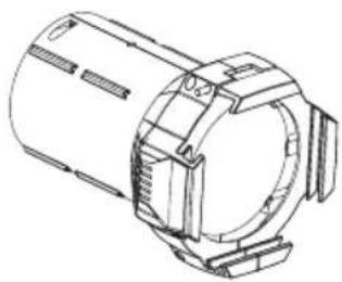
natural_image
Technical line drawing of a mechanical component with no visible text or symbolsCLP2IRIS
Iris ajustable

natural_image
Technical line drawing of a mechanical component with a cylindrical housing and mounting bracket (no text or symbols)MEDIDAS

DATOS TÉCNICOS
https://cdn-shop.adamhall.com/media/pdf/Manufacturers-Declarations-CAMEO_DE_EN_ES_FR.pdf.
TRYB SLAVE

MONTAŻ TUBUSU SOCZEWKI ZE STAŁYM KĄTEM ROZWARCIA WIĄZKI ŚWIETLNEJ
WSKAZÓWKI:
DEMONTAŻ TUBUSU Z PROWADNICĄ PRZYSŁONY WSKAZÓWKI:
natural_image
Technical line drawing of an industrial machine with a highlighted component (no text or symbols)OPRAWKA GOBO I MODUŁ IRYSOWY
natural_image
Technical line drawing of an industrial machine with labeled components A and B (no text or symbols beyond labels)
CZYSZCZENIE, KONSERWACJA I NAPRAWY
natural_image
Technical line drawing of a cylindrical mechanical component with mounting flanges and internal components (no text or symbols)CLP219LENS
natural_image
Line drawing of a target with a circular aperture and rectangular base (no text or symbols)CLP22550LENS
natural_image
Technical line drawing of a mechanical device with no visible text or symbols
natural_image
Technical line drawing of a mechanical component with no visible text or symbolsCLP2IRIS
natural_image
Technical line drawing of a mechanical component with a cylindrical housing and mounting bracket (no text or symbols)WYMIARY

DANE TECHNICZNE
https://cdn-shop.adamhall.com/media/pdf/Manufacturers-Declarations-CAMEO_DE_EN_ES_FR.pdf.
MODALITÀ SLAVE

RIMOZIONE DEL TUBO CON UNITÀ SPINGITORE DEL PANNELLO ATTENZIONE:
natural_image
Technical line drawing of an industrial machine with a highlighted component (no text or symbols)SUPPORTO PER GOBO E IRIS
natural_image
Technical line drawing of an industrial machine with labeled components A and B (no text or symbols beyond labels)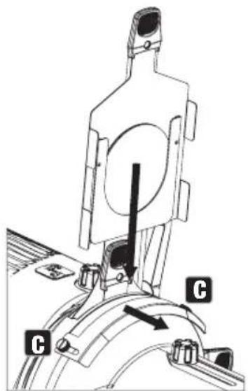
natural_image
Technical line drawing of a cylindrical mechanical component with mounting flanges and internal cavities (no text or symbols)CLP219LENS
natural_image
Technical line drawing of a mechanical component with no visible text or symbolsCLP22550LENS
natural_image
Technical line drawing of a mechanical assembly with no visible text or symbols
natural_image
Technical line drawing of a mechanical component with no visible text or symbolsCLP2IRIS
Iride regolabile
natural_image
Technical line drawing of a mechanical component with a circular housing and a vertical rod (no text or symbols)INGOMBRO

DATI TECNICI
https://cdn-shop.adamhall.com/media/pdf/Manufacturers-Declarations-CAMEO_DE_EN_ES_FR.pdf.
EN: (1*) After the adjustments have been made, set the value to 000 to avoid disturbance by endless function call.

- CONTENTS / INHALTSVERZEICHNIS / CONTENU / CONTENIDO / TREŚĆ / CONTENUTO
- ENGLISH
- DEUTSCH
- INFORMATION ON THIS USER MANUAL
- INTENDED USE
- DEFINITIONS AND SYMBOL EXPLANATIONS
- SAFETY INSTRUCTIONS
- HAZARD:
- WARNING:
- ATTENTION:
- CAUTION:
- PLEASE NOTE:
- CAUTION! IMPORTANT INFORMATION REGARDING LIGHTING PRODUCTS!
- NOTES FOR MOBILE INDOOR DEVICES
- INCLUDED
- INTRODUCTION
- CONTROL FUNCTIONS:
- FEATURES:
- POWER IN
- POWER OUT
- FUSE
- DMX IN
- DMX OUT
- IDMX STICK
- OLED DISPLAY
- DIM / MENU
- OPERATION
- NOTES
- MAIN DISPLAY DMX MODE
- SETTING DMX START ADDRESS (DMX address)
- CONFIGURING DMX MODE (DMX Mode)
- STAND ALONE MODE (Stand Alone)
- SLAVE MODE
- DEVICE SETTINGS (Settings)
- SYSTEM INFORMATION (System Info)
- INSTALLATION
- INSTALL FIXED BEAM ANGLE LENS TUBE PLEASE NOTE:
- REMOVAL OF TUBE WITH DIAPHRAGM SLIDER UNIT PLEASE NOTE:
- INSTALL ZOOM LENS TUBE WITH DIAPHRAGM SLIDER
- SOFT EDGE FILTER
- GOBO HOLDER AND IRIS
- CARE, MAINTENANCE AND REPAIR
- CARE (carried out by user)
- MAINTENANCE AND REPAIR (by qualified personnel only)
- OPTIONAL ACCESSORIES
- CLP21530LENS
- CLP219LENS
- CLP226LENS
- CLP236LENS
- CLP250LENS
- CLPGHOLDER
- CLP22550LENS
- CLP2IRIS
- MINIMUM DISTANCE TO ILLUMINATED SURFACE
- MINIMUM DISTANCE TO NORMALLY FLAMMABLE MATERIALS
- DISPOSAL
- Packaging:
- Device:
- Batteries:
- MANUFACTURER'S DECLARATIONS
- MANUFACTURER'S WARRANTY & LIMITATION OF LIABILITY
- UKCA- CONFORMITY
- UKCA- DECLARATION OF CONFORMITY
- FCC STATEMENT
- RF EXPOSURE INFORMATION
- SUBJECT TO MISPRINTS AND ERRORS, AS WELL AS TECHNICAL OR OTHER MODIFICATIONS!
- SLAVE-BETRIEB
- LINSENTUBUS MIT FIXEM ABSTRAHLWINKEL MONTIEREN HINWEISE:
- GOBOHALTER UND IRIS
- RÉGLAGE DU MODE DE FONCTIONNEMENT DMX (DMX Mode)
- MODE SLAVE
- MONTER UN TUBE DE LENTILLE AVEC UN ANGLE DE RAYONNEMENT FIXE REMARQUES :
- DÉMONTER LE TUBE AVEC L'UNITÉ COULISSANTE DE DIAPHRAGME REMARQUES :
- ENTRETIEN, MAINTENANCE ET RÉPARATION
- DÉCLARATION DE CONFORMITÉ CE
- AJUSTE DEL MODO DMX (DMX Mode)
- MODO ESCLAVO
- SOPORTE DE GOBO E IRIS
- TRYB SLAVE
- MONTAŻ TUBUSU SOCZEWKI ZE STAŁYM KĄTEM ROZWARCIA WIĄZKI ŚWIETLNEJ
- WSKAZÓWKI:
- DEMONTAŻ TUBUSU Z PROWADNICĄ PRZYSŁONY WSKAZÓWKI:
- OPRAWKA GOBO I MODUŁ IRYSOWY
- CZYSZCZENIE, KONSERWACJA I NAPRAWY
- MODALITÀ SLAVE
- RIMOZIONE DEL TUBO CON UNITÀ SPINGITORE DEL PANNELLO ATTENZIONE:
- SUPPORTO PER GOBO E IRIS
Brand : Cameo
Model : P2 T
Category : Lamp