OPUS SP5 FC - Lamp Cameo - Free user manual and instructions
Find the device manual for free OPUS SP5 FC Cameo in PDF.
| Product type | Professional LED moving head |
| Brand | Cameo |
| Model | OPUS SP5 FC |
| Light source | LED 300 W RGBAL |
| Beam angle | 6° - 44° (motorized zoom) |
| Luminous flux | 9000 lm |
| Illuminance at 5 m (narrow) | 14 000 lx |
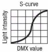
| Dimming | Yes, with adjustable curves (linear, exponential, logarithmic, S-Curve) |
| Strobe | Multifunction |
| Gobos | 13 + open (6 rotating + 7 fixed, interchangeable) |
| Prisms | 2 rotating |
| Iris | Yes |
| Frost | Yes |
| Animation wheel | Yes |
| Blades (shutters) | 4, rotating |
| Pan movement | 540° or 630° |
| Tilt movement | 270° |
| Motor resolution | 16 bits |
| Automatic position correction | Yes (adjustable feedback) |
| DMX modes | HSI-Std (36 channels), HSI-Ext (49 channels), Direct-Std (39 channels), Direct-Ext (56 channels) |
| Network protocols | Art-Net, sACN, W-DMX (wireless) |
| DMX connectors | XLR 3-pin and 5-pin IN/OUT |
| Network connectors | RJ45 IN/OUT |
| Power supply | PowerCON TRUE1 IN/OUT (max 10 A) |
| Operating voltage | 100-240 V AC, 50/60 Hz |
| Power consumption | 500 W |
| Fuse | T5AL / 250 V (5x20 mm) |
| Display | Color touchscreen, backlit, battery powered |
| Dimensions (W x H x D, without bracket) | 380 x 710 x 250 mm |
| Weight | 28.95 kg |
| Operating temperature | -15 °C to 40 °C |
| Maximum altitude | 2000 m |
| Cooling | Heat pipe + thermally regulated fans |
| Housing material | Metal and ABS |
| Mounting | 2 omega brackets supplied |
| Cleaning | Dry cloth, do not open |
| Safety | Do not stare directly at light source; min. distance 0.5 m from flammable materials |
| Spare parts / repairability | Identical fuse required; interchangeable gobos; repair by authorized personnel only |
Frequently Asked Questions - OPUS SP5 FC Cameo
User questions about OPUS SP5 FC Cameo
0 question about this device. Answer the ones you know or ask your own.
Ask a new question about this device
Download the instructions for your Lamp in PDF format for free! Find your manual OPUS SP5 FC - Cameo and take your electronic device back in hand. On this page are published all the documents necessary for the use of your device. OPUS SP5 FC by Cameo.
USER MANUAL OPUS SP5 FC Cameo
natural_image
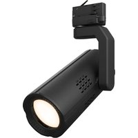
Black camera boom-mounted optical system with green lens and display (no visible text or symbols on device body)OPUS® SP5 FC
PROFILE SPOT MOVING HEAD
CLOSP5FC
CONTENTS / INHALTSVERZEICHNIS / CONTENU / CONTENIDO / TREŚĆ / CONTENUTO
ENGLISH
PREVENTIVE MEASURES 3
INTRODUCTION
CONNECTIONS, CONTROL AND DISPLAY ELEMENTS 5
OPERATION
CONTROL MENU (CONTROL) 8
SYSTEM SETTINGS (SETTINGS) 11
SERVICE MENU 12
DEVICE INFO (INFO) 13
DMX TECHNOLOGY 14
TECHNICAL SPECIFICATIONS 15
MANUFACTURER'S DECLARATIONS 17
DMX
DEUTSCH
SICHERHEITSHINWEISE
EINFÜHRUNG
We have designed this product to operate reliably over many years. Please read this User's Manual carefully, so that you can begin making optimum use of your Cameo Light product quickly. Learn more about Cameo Light on our website WWW.CAMEOLIGHT.COM.
PREVENTIVE MEASURES
- Please read these instructions carefully.
- Keep all information and instructions in a safe place.
- Follow the instructions.
- Observe all safety warnings. Never remove safety warnings or other information from the equipment.
- Use the equipment only in the intended manner and for the intended purpose.
- Use only sufficiently stable and compatible stands and/or mounts (for fixed installations). Make certain that wall mounts are properly installed and secured. Make certain that the equipment is installed securely and cannot fall down.
- During installation, observ e the applicable safety regulations for your country.
- Never install and operate the equipment near radiators, heat registers, ovens or other sources of heat. Make certain that the equipment is always installed so that is cooled sufficiently and cannot overheat.
-
Never place sources of ignition, e.g., burning candles, on the equipment.
-
Ventilation slits must not be blocked.
-
This appliance is designed exclusively for indoor use, do not use this equipment in the immediate vicinity of water (does not apply to special outdoor equipment - in this case, observe the special instructions noted below). Do not expose this equipment to flammable materials, fluids or gases.
-
Make certain that dripping or splashed water cannot enter the equipment. Do not place containers filled with liquids, such as vases or drinking vessels, on the equipment.
-
Make certain that objects cannot fall into the device.
-
Use this equipment only with the accessories recommended and intended by the manufacturer.
-
Do not open or modify this equipment.
-
After connecting the equipment, check all cables in order to prevent damage or accidents, e.g., due to tripping hazards.
-
During transport, make certain that the equipment cannot fall down and possibly cause property damage and personal injuries.
-
If your equipment is no longer functioning properly, if fluids or objects have gotten inside the equipment or if it has been damaged in anot her way, switch it off immediately and unplug it from the mains outlet (if it is a powered device). This equipment may only be repaired by authorized, qualified personnel.
-
Clean the equipment using a dry cloth.
-
Comply with all applicable disposal laws in your country. During disposal of packaging, please separate plastic and paper/cardboard.
-
Plastic bags must be kept out of reach of children.
FOR EQUIPMENT THAT CONNECTS TO THE POWER MAINS:
-
CAUTION: If the power cord of the device is equipped with an earthing contact, then it must be connected to an outlet with a protective ground. Never deactivate the protective ground of a power cord.
-
If the equipment has been exposed to strong fluctuations in temperature (for example, after transport), do not switch it on immediately. Moisture and condensation could damage the equipment. Do not switch on the equipment until it has reached room temperature.
-
Before connecting the equipment to the power outlet, first verify that the mains voltage and frequency match the values specified on the equipment. If the equipment has a voltage selection switch, connect the equipment to the power outlet only if the equipment values and the mains power values match. If the included power cord or power adapter does not fit in your wall outlet, contact your electrician.
-
Do not step on the power cord. Make certain that the power cable does not become kinked, especially at the mains outlet and/or power adapter and the equipment connector.
-
When connecting the equipment, make certain that the power cord or power adapter is always freely accessible. Always disconnect the equipment from the power supply if the equipment is not in use or if you want to clean the equipment. Always unplug the power cord and power adapter from the power outlet at the plug or adapter and not by pulling on the cord. Never touch the power cord and power adapter with wet hands.
-
Whenever possible, avoid switching the equipment on and off in quick succession because otherwise this can shorten the useful life of the equipment.
-
IMPORTANT INFORMATION: Replace fuses only with fuses of the same type and rating. If a fuse blows repeatedly, please contact an authorised service centre.
-
To disconnect the equipment from the power mains completely, unplug the power cord or power adapter from the power outlet.
-
If your device is equipped with a Volex power connector, the mating Volex equipment connector must be unlocked before it can be removed. However, this also means that the equipment can slide and fall down if the power cable is pulled, which can lead to personal injuries and/or other damage. For this reason, always be careful when laying cables.
-
Unplug the power cord and power adapter from the power outlet if there is a risk of a lightning strike or before extended periods of disuse.
-
The device must only be installed in a voltage-free condition (disconnect the mains plug from the mains).
-
Dust and other debris inside the unit may cause damage. The unit should be regularly serviced or cleaned (no guarantee) depending on ambient conditions (dust etc., nicotine, fog) by qualified personnel to prevent overheating and malfunction.
-
Please keep a distance of at least 0.5 m to any combustible materials.
-
Power cables to power multiple devices must have a cross-section of at least 1.5 mm ^2 . Within the EU, the cables must correspond to H05VV-F, or similar. Suitable cables are offered by Adam Hall. With these cables, you can connect multiple devices via the power OUT connection to the power IN connection of an additional device. Make sure that the total current consumption of all connected devices does not exceed the specified value on all connected devices (label on the device). Make sure to keep power cable connections as short as possible.
-
The appliance is not to be used by persons (including children) with reduced physical, sensory or mental capabilities, or lack of experience and knowledge.
- Children must be instructed not to play with the device.
- If the power cord of the device is damaged, do not use the device. The power cord must be replaced by an adequate cable or assembly from an authorized service center.

CAUTION:
To reduce the risk of electric shock, do not remove cover (or back). There are no user serviceable parts inside. Maintenance and repairs should be exclusively carried out by qualified service personnel.
The warning triangle with lightning symbol indicates dangerous uninsulated voltage inside the unit, which may cause an electrical shock.

The warning triangle with exclamation mark indicates important operating and maintenance instructions.

Warning! This symbol indicates a hot surface. Certain parts of the housing can become hot during operation. After use, wait for a cool-down period of at least 10 minutes before handling or transporting the device.

Warning! This device is designed for use below 2000 metres in altitude.

Warning! This product is not intended for use in tropical climates.

Caution! Intense LED light source! Risk of eye damage. Do not look into the light source.
CAUTION! IMPORTANT INFORMATION ABOUT LIGHTING PRODUCTS!
- The product has been developed for professional use in the field of event technology and is not suitable as household lighting.
- Do not stare, even temporarily, directly into the light beam.
- Do not look at the beam directly with optical instruments such as magnifiers.
- Stroboscope effects may cause epileptic seizures in sensitive people! People with epilepsy should definitely avoid places where strobes are used.
INTRODUCTION
MOVING HEAD OPUS SERIES
CLOSP5FC
CONTROL FUNCTIONS
36-, 49-, 39-, 56-channel DMX control
Art-Net
sACN
W-DMX ^TM
RDM enabled
Master/slave mode
Stand-alone functions
PROPERTIES
300 W RGBAL LED. Animation wheel. Framing blades. Gobo wheel 1 with 6 rotating gobos + open, gobo wheel 2 with 7 fixed gobos + open (gobos are exchangeable). 2 rotating prisms. Focusing and zoom function via DMX. Frost filter and iris. Multifunctional strobe. Pan and tilt motors with 16-bit resolution. Battery-powered display for configuration when not connected to power. Automatic position correction. Temperature-controlled fans. 3- and 5-pin DMX connectors. RJ45 network connectors. Wireless DMX™. Neutrik powerCON TRUE1 mains connector, IN and OUT. 2 omega mounting brackets included. Operating voltage: 100–240 V AC. Power consumption 500 W.
The spotlight complies with the RDM standard (Remote Device Management). Remote device management allows the user to view the status and configuration of RDM terminals via an RDM-capable controller.
CONNECTIONS, CONTROL AND DISPLAY ELEMENTS

text_image
POWER IN: 100-240 V AC 50-60 Hz POWER CONSUMPTION: 500 W · WEIGHT: 28.95 kg FUSE TSAL / 250 V POWER IN POWER OUT NET IN DMX IN DMX OUT 3 1 2 7 4 5 NET OUT DMX IN DMX OUT Cameo® is a brand of the Adam Hall Group. Adam-Hall-50; 1 - 61267 Neo-Anspach - Germany DESIGNED AND ENGINEERED IN GERMANY, Assembled in PRC MAX: 10 A1 POWER IN
Neutrik powerCON TRUE1 mains input socket. Operating voltage: 100–240 V AC / 50–60 Hz. A suitable power cable with powerCON TRUE1 plug is included in delivery.
2 POWER OUT
Neutrik powerCON TRUE1 mains output socket. Provides power to additional CAMEO spotlights. Ensure that the total power consumption of all devices connected to the device does not exceed the given ampere (A) value.
3 FUSE
Fuse holder for 5 x 20 mm micro fuses. IMPORTANT NOTE: Exclusively replace the fuse with a fuse of the same type and values. If a fuse trips repeatedly, please contact an authorized service center.
4 DMX IN
Male 3- and 5-pin XLR connectors to connect a DMX control device (e.g., DMX console).
5 DMX OUT
Female 3- and 5-pin XLR connectors to transmit the DMX control signal.
6 NET IN
RJ45 network connector to connect with an Art-Net or sACN network. Use CAT-5e, or later, cables to set up the network.
7 NET OUT
RJ45 network connector to connect additional Art-Net-capable or sACN-capable devices to the network. Use CAT-5e, or later, cables to set up the network.
8 ANTENNA FOR W-DMX™
The antenna for W-DMX ^TM control remains in its holder during operation (= operating position).

text_image
cameo® colours of light OPUS® SP5 FC 9 Cameo Opus SP5 FC Cameo® is a brand of the Adam Hall Group. www.adamhall.com MODE UP 10 LEFT ENTER RIGHT DOWN9 PRESSURE-SENSITIVE LC-DISPLAY WITH BACKLIGHTING
Thanks to the pressure-sensitive LC display, the device can be operated directly from the display (can be used with gloves). The display shows the currently active operating mode (main display), the menu options in the Options menu, and the numerical values or operating status for certain menu options. If there is no control signal to the device, the display will begin to flash. This flashing will stop as soon as a control signal is received (DMX and Slave mode, ArtNet, and sACN).
10 TOUCH-SENSITIVE CONTROLS
MODE—Press MODE (repeatedly) to go one level higher in the menu structure to the main display.
UP ▲ and DOWN ▼—Selects the individual menu options in the main menu (DMX address, operating mode, etc.) and in the submenus.
ENTER—Starting from the main display, press ENTER to go to the main menu. In the main menu, press ENTER to access the menu level where you can change values. You can also confirm value adjustments by pressing ENTER.
LEFT ◀ and RIGHT ▶—Use these buttons to change the value, for instance the DMX address, as desired.
11 USB INTERFACE
USB interface to update the device firmware. In the Service menu, set USB Update to ON. Download, when available, the current firmware from the product page at www.cameolight.com, unzip it, and copy the files to a folder without any special characters on a USB stick. Disconnect the moving head from the power and all input connections (DMX/Ethernet), connect the USB stick via the USB port, and then reconnect the moving head to the power. The USB stick will be automatically detected and shown on the display. Now navigate to the corresponding folder on the USB stick and confirm with "ON". The update process will begin. Do not remove the USB stick or disconnect the moving head from the power during the update process.
The battery-powered display can be activated even if the device is not connected to the power. To do so, press and hold MODE for a period of 12 seconds. You can now view device information and change and save system settings, even if the device is not connected to the power. The external controller of the spotlight will not activate in this case. This means that the display will show that there is no control signal present, even if there is one present for the device.

natural_image
Close-up of a mechanical device with labeled parts (12 and 13), showing internal components and mounting holes (no readable text or symbols beyond labels)OPERATION
NOTE:
As soon as the spotlight is connected correctly to the power, "Software Update Please Wait..." and the Cameo logo with information on the device model will display while the device starts up and the motor resets. The spotlight is ready after this process, and the operating mode that was previously selected will activate.
The spotlight can be operated using the touch-sensitive control fields next to the display, or the pressure-sensitive display (can be used with gloves) itself can be used to access all menu options and intuitively modify settings as desired. Information on which control element on the display and which control field next to the display have the same functionality can be found in the adjacent table.
The following describes how to operate the device using the control fields next to the display.
12 PAN LOCK
Mechanical locking mechanism to prevent the head from turning in a horizontal direction during transport. Disconnect the device from the power, position the head parallel to the base (4 positions), and disengage the locking lever to unlock in the direction of the panning rotation axis. Unlatch the mechanism before starting up the device.
13 TILT LOCK
Mechanical locking mechanism to prevent the head from turning in a vertical direction during transport (7 positions). Disconnect the device from the power and push the locking lever to unlock in the direction of the tilting rotation axis, move the device head vertically until one of the 7 stopping points is reached and the locking lever engages. Unlatch the mechanism before starting up the device.
| Display Control panel | |
| MODE | |
| UP | |
| ENTER | |
| DOWN | |
| LEFT | |
| RIGHT | |
MAIN DISPLAY
The upper line of the display shows whether and which control signal is present on the device. The line below shows the currently active control mode (HSI-Std, HSI-Ext, Direct-Std, Direct-Ext, Static, Auto, Slave), and clearly visible in the middle is the DMX start address or the corresponding operating mode (e.g., DMX start address 001). As soon as the control signal is interrupted, the numbers on the display will begin to flash and "None" will display after "Signal" on the upper line (no signal). When the control signal is again present, the screen will switch back to the main display. The display can be rotated by 180^ by pressing the touch-sensitive DOWN control key. If the display is already rotated 180^ , press the UP control key to return the display to its standard position. The display can also be rotated 180^ by pressing the "roof" symbol on the pressure-sensitive display.

text_image
Input signal display DMX mode or operating mode Signal:DMX User Mode:Direct-Ext Battery status display Rotate display by 180° DMX start address or operating mode 001 Information on device model Return to main display = press anywhere on display or ENTER Main menu
CONTROL MENU (Control)
SETTING THE DMX START ADDRESS (DMX Address)
Starting from the main display, press ENTER to go to the main menu. Use the UP and DOWN control keys to select the Control menu and press ENTER. Using the UP and DOWN buttons, now select the "DMX Address" menu option and confirm via ENTER. Set the desired DMX start address using the LEFT and RIGHT buttons and confirm via ENTER (highest value depends on active DMX mode). Press MODE 2x to return to the main display, the selected DMX start address will now be displayed enlarged when the DMX mode is active.

text_image
Control DMX Address DMX Mode Network Wireless Stand Alone
text_image
DMX Address 001SETTING THE DMX MODE (DMX Mode)
Starting from the main display, press ENTER to go to the main menu. Use the UP and DOWN control keys to select the Control menu and press ENTER. Using the UP and DOWN buttons, now select the "DMX Mode" menu option and confirm via ENTER. In turn, select the desired DMX mode via UP and DOWN and confirm with ENTER. Press MODE 2x to return to the main display, the selected DMX mode is now active. You can find tables on channel assignment in the different DMX modes in these instructions under DMX CONTROL.

text_image
Control DMX Address DMX Mode Network Wireless Stand Alone
text_image
DMX Mode HSI-Std HSI-Ext Direct-Std Direct-ExtNETWORK SETTINGS (Network)
Starting from the main display, press ENTER to go to the main menu. Use the UP and DOWN control keys to select the Control menu and press ENTER. Using the UP and DOWN buttons, now select the "Network" menu option and confirm via ENTER. Network settings information can be found in the following table. Confirm all network settings changes via ENTER.

text_image
Control DMX Address DMX Mode Network Wireless Stand Alone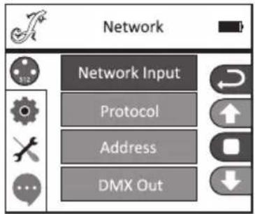
text_image
Network Network Input Protocol Address DMX Out| Network | |||
| Network Input Activate/deactivate network input OFF Network | work input deactivated | ||
| ON Network input activated | |||
| Protocol Network protocol ArtNET ArtNet protocol | |||
| sACN sACN protocol | |||
| Address Universe 1-256, configureIP address and subnet mask | Universe000-255 | 000 to 255. Change value via LEFT and RIGHT, confirm via ENTER. | |
| IP address Select Block via LEFT and RIGHT, change value via UP and DOWN, confirm with ENTER. | |||
| IP Subnet Mask Select Block via LEFT and RIGHT, change value via UP and DOWN, confirm with ENTER. | |||
| DMX OUT Output network signal via DMX OUT | OFF Do not output signal | ||
| ON Output signal | |||
W-DMX SETTINGS (Wireless)
Starting from the main display, press ENTER to go to the main menu. Use the UP and DOWN control keys to select the Control menu and press ENTER. Using the UP and DOWN buttons, now select the "Mode" menu option and confirm via ENTER. W-DMX settings information can be found in the following table. Confirm all changes made to the settings via ENTER.

text_image
Control DMX Address DMX Mode Network Wireless Stand Alone
text_image
Wireless W-DMX Operating Transmitting Link Receive Reset| Wireless | ||
| W-DMX OFF Deactivate W-DMX | ||
| Operating Receiver | W-DMX module configured as receiver | |
| Transmitter | W-DMX module configured as transmitter | |
| Transmitting | G3 | G3 transmission standard |
| G4S | G4S transmission standard | |
| Link | Link | Link with W-DMX devices. W-DMX must be active for all devices and the link with a transmitter must be suspended (Receive Reset) |
| UnLink Unlink all devices | ||
| Receive Reset NO Do not suspend link with a transmitter | ||
STAND-ALONE MODES (Stand Alone)
Starting from the main display, press ENTER to go to the main menu. Use the UP and DOWN control keys to select the Control menu and press ENTER. Using the UP and DOWN buttons, now select the "Stand-Alone" menu option and confirm via ENTER. Now select one of the three stand-alone modes using the UP and DOWN control keys and confirm via ENTER.

text_image
Control DMX Address DMX Mode Network Wireless Stand AloneSTAND ALONE STATIC MODE (Static)
Static mode makes it possible, as with a DMX control device, to configure PAN, TILT, Dimmer, Strobe, Color Wheel, and Gobo Wheel from 000 to 255 directly on the device. This allows the user to create individual scenes without needing an additional DMX controller. You can configure the settings as desired after you have selected Static mode, as described under "STANDALONE MODES". The submenu options here correspond to channels 1 to 54 in the Direct Extended DMX mode (see DMX CONTROL, select submenu options via UP and DOWN, change value via LEFT and RIGHT, confirm via ENTER). Press MODE again to return to the main screen.

text_image
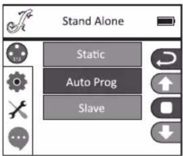
Stand Alone Static Auto Prog SlaveSTAND-ALONE AUTO PROGRAM (Auto Prog)
The 4 different Auto programs (Program 1–4) consist of pre-programmed head movements, gobo and color changes, etc.; the speed is configured separately. Select Auto mode, as described previously under "STAND-ALONE MODES", confirm via ENTER, select the desired Auto program via UP and DOWN, confirm via ENTER, and now change the value for the speed from 000 to 100 via LEFT and RIGHT as desired. Confirm with ENTER. Press MODE again to return to the main screen.
text_image
Stand Alone Static Auto Prog Slave
text_image
Auto Prog Program 1 Program 2 Program 3 Program 4
text_image
Program 1 Speed 000-100 - +SLAVE MODE (Slave)
Select Slave mode as described previously under "STAND-ALONE MODES". Connect the slave and master unit (same model, same software version) using a DMX cable (Master DMX OUT—Slave DMX IN), and activate one of the stand-alone modes, Auto or Static, on the master unit. The slave unit will now follow the master unit. Press MODE again to return to the main screen.

text_image
Stand Alone Static Auto Prog Slave
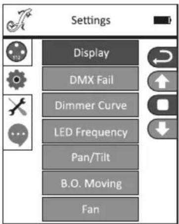
SYSTEM SETTINGS (Settings)
Starting from the main display, press ENTER to go to the main menu. Use the UP and DOWN control keys to select the System Settings menu and press ENTER.
text_image
Settings Display DMX Fail Dimmer Curve LED Frequency Pan/Tilt B.O. Moving FanThis will take you to the submenu for setting the submenu options, see table (select via UP and DOWN, confirm via ENTER, change status via UP and DOWN, confirm via ENTER):
| Settings (bold = factory setting) | ||||||
| Display Display settings Reverse OFF Display does not rotate | ||||||
| ON Display rotates by 180° (when installed overhead) | ||||||
| Backlight OFF Deactivates display backlight after approx. 30 seconds of inactivity | ||||||
| ON Display backlight permanently on | ||||||
| DMX Fail Operating status if DMX signal is lost | Black Activates Blackout | |||||
| Hold Last command is held | ||||||
| Auto Activates auto mode | ||||||
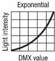
| Dimmer Curve Select the dimmer curve | Linear The light intensity climbs linearly with the DMX value | |||||
| Exponential The light intensity can be set finely in the lower DMX value range and roughly in the upper DMX value range | ||||||
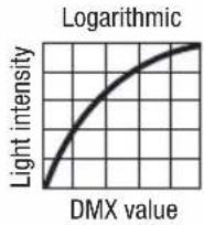
| Logarithmic The light intensity can be set roughly in the lower DMX value range and finely in the upper DMX value range | ||||||
| S-curve | The light intensity can be set finely in the lower and upper DMX value ranges and roughly in the medium DMX value range | |||||
| LED Frequency Sets | the LED PWM frequency | 650 Hz, 1530 Hz, 3600 Hz, 12 KHz, 25 KHz | ||||
| Pan/Tilt Configures | the device head | Pan Reverse OFF Pan | movement direction does not reverse | |||
| ON Pan movement direction reverses | ||||||
| Tilt Reverse OFF Tilt | movement direction does not reverse | |||||
| ON Tilt movement direction reverses | ||||||
| Pan Angle 630 Pan angle 630° | ||||||
| 540 Pan angle 540° | ||||||
| Feedback OFF Automatic position correction deactivated | ||||||
| ON Automatic position correction activated | ||||||
| B.O. Moving Automatic | blackout when head moves | OFF No blackout when head moves | ||||
| ON | Blackout when head moves | |||||
| Fan | Fan control | Head Fan | Auto | The fan speed will adjust automatically to the temperature of the device head | ||
| Low Consistently low fan speed with reduced brightness, as required | ||||||
| Base Fan | Auto | The fan speed will adjust automatically to the temperature of the device base | ||||
| Low Consistently low fan speed with reduced brightness, as required | ||||||
Dimmer curves

SERVICE MENU
Starting from the main display, press ENTER to go to the main menu. Use the UP and DOWN control keys to select the Service menu and press ENTER.
text_image
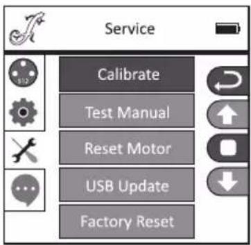
Service Calibrate Test Manual Reset Motor USB Update Factory ResetThis will take you to the submenu for adjusting the submenu options (select via UP and DOWN, confirm via ENTER, change value via LEFT and RIGHT, confirm via ENTER).
Calibrate—Calibrate the components with values of 000 to 255 (Password 050).
Test Manual—Manually test the components with values of 000 to 255.
Reset Motor—Reset the motors. All = All motors, Pan&Tilt = Pan and tilt motors, Head Only = Motors in device head.
USB Update—Firmware update via USB interface. OFF = Block firmware update via USB interface. ON = Allow firmware update via USB interface.
Factory Reset—Reset to factory settings.

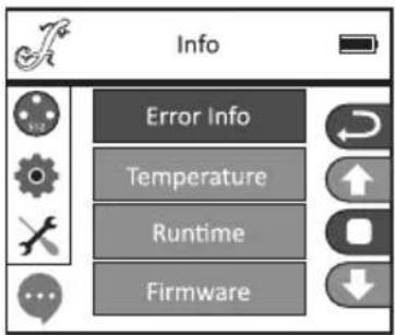
DEVICE INFO (Info)
Starting from the main display, press ENTER to go to the main menu. Use the UP and DOWN control keys to select the Infomenu and press ENTER.
text_image
Info Error Info Temperature Runtime FirmwareThis will take you to the submenu to view the device information (select via UP and DOWN, confirm with ENTER).
| System Info | |||
| Error Info Functional | error displayIf it is not possible to eliminate a functional error by resetting or restarting, the faulty unit must be repaired by an authorized service center. | ||
| Temperature Temperature display Head xx°C/F° | |||
| Base xx°C/F° | |||
| Unit Displays the temperature in Celsius or Fahrenheit | |||
| Runtime | Displays operating time | Total Time | Displays the total operating time in hours |
| Current Time Displays the current operating time | |||
| Time PW Inputs the password to reset the current operating time(Time PW = 050) | |||
| Clean Current Resets the current operating time | |||
| Firmware Displays the firmware of components 1U to 8U | Vx.x.x | ||
SETUP AND INSTALLATION
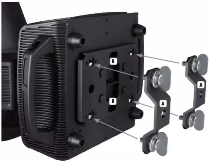
Thanks to the integrated rubber feet, the spotlight can be placed in a suitable location on a flat and solid surface. Install on a crossbeam using two omega brackets that are attached to the base of the device (A). Two omega brackets are included in the scope of delivery; suitable crossbeam clamps are available as needed. Make sure that the spotlight is firmly attached and secure it using a suitable safety cable on the designated location (B).

Important info: Overhead installation requires extensive experience, which includes calculating the limit values of the working load, of the installation material to be used, and regularly conducting safety inspections of all installation materials and spotlights. If you do not have these qualifications, do not attempt to carry out the installation yourself; contact a professional company.
text_image
Technical diagram of a mechanical assembly with labeled parts A, B, and C, showing internal components and mounting features.DMX TECHNOLOGY
DMX-512
DMX (Digital Multiplex) is the designation for a universal transmission protocol for communications between corresponding devices and controllers. A DMX controller sends DMX data to the connected DMX device(s). The DMX data is always transmitted as a serial data stream that is forwarded from one connected device to the next via the "DMX IN" and "DMX OUT" connectors (XLR plug-type connectors) that are found on every DMX-capable device, provided the maximum number of devices does not exceed 32 units. The last device in the chain needs to be equipped with a terminator (terminating resistor).

natural_image
Coiled black cable with two connectors and a terminal connector (no text or symbols visible)DMX CONNECTION
DMX is the common "language" via which a very wide range of types and models of equipment from various manufacturers can be connected with one another and controlled via a central controller, provided that all of the devices and the controller are DMX compatible. For optimum data transmission, it is necessary to keep the connecting cables between the individual devices as short as possible. The order in which the devices are integrated in the DMX network has no influence on the addresses. Thus the device with the DMX address 1 can be located at any position in the (serial) DMX chain: at the beginning, at the end or somewhere in the middle. If the DMX address 1 is assigned to a device, the controller "knows" that it should send all data allocated to address 1 to this device regardless of its position in the DMX network.
SERIAL CONNECTION OF MULTIPLE LIGHTS
- Connect the male XLR connector (3-pin or 5-pin) of the DMX cable to the DMX output (female XLR socket) of the first DMX device (e.g. DMX-Controller).
- Connect the female 3-pin XLR connector of the DMX cable connected to the first projector to the DMX input (male 3-pin socket) of the next DMX device. In the same way, connect the DMX output of this device to the DMX input of the next device and repeat until all devices have been connected. Please note that as a rule, DMX devices are connected in series and connections cannot be shared without active splitters. The maximum number of DMX devices in a DMX chain should not exceed 32 units.
The Adam Hall 3 STAR, 4 STAR, and 5 STAR product ranges include an extensive selection of suitable cables.
DMX CABLES
When fabricating your own cables, always observe the illustrations on this page. Never connect the shielding of the cable to the ground contact of the plug, and always make certain that the shielding does not come into contact with the housing of the XLR plug. If the shielding is connected to the ground, this can lead to short-circuiting and system malfunctions.
Pin Assignment
DMX cable with 3-pin XLR connectors: DMX cable with 5-pin XLR connectors (pin 4 and 5 are not used):

flowchart
graph LR
    A["1"] --> B["Shield"]
    C["3"] --> B
    D["2"] --> B
    B --> E["1"]
    B --> F["3"]
    B --> G["2"]
    H["DMX +"] --> I["Shield"]
    J["DMX -"] --> K["Shield"]

DMX TERMINATORS (TERMINATING RESISTORS)
To prevent system errors, the last device in a DMX chain needs to be equipped with a terminating resistor (120 ohm, 1/4 Watt).
3-pin XLR connector with a terminating resistor: K3DMXT3
5-pin XLR connector with a terminating resistor: K3DMXT5
Pin Assignment
3-pin XLR connector: 5-pin XLR connector:


DMX ADAPTER
The combination of DMX devices with 3-pin connectors and DMX devices with 5-pin connectors in a DMX chain is possible with suitable adapters.
Pin Assignment
DMX Adapter 5-pin XLR male to 3-pin XLR female: K3DGF0020
Pins 4 and 5 are not used.
Pin Assignment
DMX Adapter 3-pin XLR male to 5-pin XLR female: K3DHM0020
Pins 4 and 5 are not used.

text_image
DMX + DMX - Shield
text_image
DMX + DMX - ShieldTECHNICAL SPECIFICATIONS
Article number: CLOSP5FC
Product type: LED moving light
Type: Moving head
Number of lamps: 1
Type of lamps: 300 W LED
Color spectrum of lamps: RGBAL
LED PWM frequency: 650 Hz, 1530 Hz, 3600 Hz, 12000 Hz, 25000 Hz (configurable)
Number of gobos: 13 + open (6 rotating + 7 fixed)
Gobo size: ∅ outside 29.9 mm (-0.2 mm), ∅ motif 25 mm, material thickness 1.1 mm (glass)
Beam angle: 6° to 44°
| DMX input: | 3-pin XLR male5-pin XLR male |
| DMX output: | 3-pin XLR female5-pin XLR female |
Network connectors: RJ45 IN and OUT (lockable)
DMX mode: HSI-Standard 36-channel, HSI-Extended 49-channel, Direct-Standard 39-channel, Direct-Extended 56-channel
DMX functions: Pan/Tilt, Pan/Tilt fine, Dimmer, Dimmer fine, multifunctional strobe, RGBAL, RGBAL fine, Hue,
Hue fine, Saturation, CTC, Shade, Color macros, Color macros Crossfade, Gobo Wheel 1, Gobo 1 Rotation, Gobo 1 Rotation fine, Gobo Wheel 1 Rotation, Gobo 1 Shake, Gobo Wheel 2, Gobo Wheel 2 Rotation, Gobo 2 Shake, Zoom, Zoom fine, Focus, Focus fine, Iris, Prism 1/2, Prism Rotation, Frost, Animation Wheel, Diaphragm Slide 1–4, Diaphragm Slide Rotation, Diaphragm Slide Rotation fine, Pan/Tilt Macros, Pan/Tilt Speed, Dimmer Curve, System Settings
Standalone functions: Auto Program 1–4, Static Mode, Master/Slave Mode
System settings: Wireless Setting, Display Reverse, Display Backlight On/Off, DMX Fail, Dimmer Curve, LED PWM Frequency, Pan Angle, Pan Reverse, Tilt Reverse, Feedback, Movement Blackout, Fan Settings, Calibration, Manual Test, Motor Reset, Factory Reset, Network Settings
Controller: DMX512, RDM enabled, W-DMX™ (receiver), Art-Net, sACN
PAN angle: 540°/630°
TILT angle: 270°
Control elements: Touch-sensitive MODE, ENTER, UP, DOWN, LEFT, RIGHT control keys, pressure-sensitive graphic color LC display (can be used while wearing gloves)
Display elements: Backlit graphic color LC display, battery-powered to configure system settings without being connected to power
Operating voltage: 100–240 V AC / 50–60 Hz
Power consumption: 500 W
Illumination intensity: 14000 lx @ 5 m (narrow)
Luminous flux: 9000 lm
Power supply connection: Neutrik powerCON TRUE1 in and out (max. output 10 A)
Fuse: T5AL / 250 V (5 x 20 mm)
Ambient temperature in use: -15^ to 40^
Relative humidity: < 85%, non-condensing
Housing material: Metal, ABS
Housing color: Black
Housing cooling: Heatpipe cooling system plus temperature-controlled fans
Dimensions 380 x 710 x 250 mm (W x H x D, without mounting bracket):
Weight: 28.95 kg
Additional features: 1 m power cable with powerCON TRUE1 plug and 2 omega mounting brackets included in delivery
MANUFACTURER'S DECLARATIONS
MANUFACTURER'S WARRANTY & LIMITATIONS OF LIABILITY
You can find our current warranty conditions and limitations of liability at: https://cdn-shop.adamhall.com/media/pdf/MANUFACTURERS-DECLARATIONS_CAMEO.pdf. To request warranty service for a product, please contact Adam Hall GmbH, Adam-Hall-Str. 1, 61267 Neu Anspach / Email: Info@adamhall.com / +49 (0)6081 / 9419-0.

CORRECT DISPOSAL OF THIS PRODUCT
(valid in the European Union and other European countries with a differentiated waste collection system)
This symbol on the product, or on its documents indicates that the device may not be treated as household waste. This is to avoid environmental damage or personal injury due to uncontrolled waste disposal. Please dispose of this product separately from other waste and have it recycled to promote sustainable economic activity. Household users should contact either the retailer where they purchased this product, or their local government office, for details on where and how they can recycle this item in an environmentally friendly manner. Business users should contact their supplier and check the terms and conditions of the purchase contract. This product should not be mixed with other commercial waste for disposal.
FCC STATEMENT
This device complies with Part 15 of the FCC Rules. Operation is subject to the following two conditions:
(1) This device may not cause harmful interference, and
(2) This device must accept any interference received, including interference that may cause undesired operation
CE Compliance
Adam Hall GmbH states that this product meets the following guidelines (where applicable):
R&TTE (1999/5/EC) or RED (2014/53/EU) from June 2017
Low voltage directive (2014/35/EU)
EMV directive (2014/30/EU)
RoHS (2011/65/EU)
The complete declaration of conformity can be found at www.adamhall.com.
Furthermore, you may also direct your enquiry to info@adamhall.com.
DEUTSCH
natural_image
Close-up of a mechanical device with labeled parts (12 and 13), showing internal components and mounting holes (no readable text or symbols beyond labels)12 PAN LOCK
text_image
Wireless W-DMX Operating Transmitting Link Receive Resettext_image
Auto Prog Program 1 Program 2 Program 3 Program 4
text_image
Program 1 Speed 000-100 - +text_image
Settings Display DMX Fail Dimmer Curve LED Frequency Pan/Tilt B.O. Moving Fantext_image
Technical diagram of a mechanical assembly with labeled parts A and B, showing internal components and mounting features.DMX TECHNIK
DMX-512
natural_image
Coiled black cable with two connectors and a terminal connector (no text or symbols visible)DMX-VERBINDUNG:
Steuerung: DMX512, RDM enabled, W-DMX™ (Receiver), Art-Net, sACN
PAN Winkel: 540°/630°
TILT Winkel: 270°
natural_image
Close-up of a black mechanical device with labeled parts (12 and 13), showing internal components and mounting holes (no readable text or symbols beyond labels)12 PAN LOCK
PARAMÈTRES W-DMX (Wireless)
text_image
Wireless W-DMX Operating Transmitting Link Receive Resettext_image
Auto Prog Program 1 Program 2 Program 3 Program 4
text_image
Program 1 Speed 000-100 - +MODE SLAVE (Slave)
text_image
Settings Display DMX Fail Dimmer Curve LED Frequency Pan/Tilt B.O. Moving Fantext_image
Technical diagram of a mechanical assembly with labeled parts A and B, showing internal components and mounting features.TECHNIQUE DMX
DMX-512
natural_image
Coiled black cable with two connectors and a connector pin (no text or symbols visible)PROTOCOLE DMX
(Valid in the European Union and other European countries with waste separation)
natural_image
Close-up of a mechanical device with labeled parts (12 and 13), showing internal components and mounting holes (no readable text or symbols beyond labels)12 PAN LOCK
text_image
Wireless W-DMX Operating Transmitting Link Receive Resettext_image
Auto Prog Program 1 Program 2 Program 3 Program 4
text_image
Program 1 Speed 000-100 - +MODO ESCLAVO (Slave)
text_image
Settings Display DMX Fail Dimmer Curve LED Frequency Pan/Tilt B.O. Moving Fantext_image
Technical diagram of a mechanical assembly with labeled parts A, B, and C, showing internal components and mounting features.TECNOLOGÍA DMX
DMX512
natural_image
Coiled black cable with two connectors and a connector pin (no text or symbols visible)CONEXIONADO DMX
natural_image
Close-up of a mechanical device with labeled parts (12 and 13), showing internal components and mounting holes (no readable text or symbols beyond labels)12 PAN LOCK
USTAWIENIA W-DMX (Wireless)
text_image
Wireless W-DMX Operating Transmitting Link Receive Resettext_image
Auto Prog Program 1 Program 2 Program 3 Program 4
text_image
Program 1 Speed 000-100 - +TRYB SLAVE (Slave)
text_image
Settings Display DMX Fail Dimmer Curve LED Frequency Pan/Tilt B.O. Moving Fantext_image
Technical diagram of a mechanical assembly with labeled parts A, B, and C, showing internal components and mounting features.TECHNIKA DMX
DMX-512
natural_image
Coiled black cable with two connectors and three terminal ports (no text or symbols visible)ZŁACZE DMX:
natural_image
Close-up of a mechanical device with labeled parts (12 and 13), showing internal components and mounting holes (no readable text or symbols beyond labels)UTILIZZO
NOTE
text_image
Wireless W-DMX Operating Transmitting Link Receive Resettext_image
Auto Prog Program 1 Program 2 Program 3 Program 4