
OPUS SP5 Plus - Lamp Cameo - Free user manual and instructions
Find the device manual for free OPUS SP5 Plus Cameo in PDF.
| Product Type | Professional LED moving head |
| Brand | Cameo |
| Model | OPUS SP5 Plus |
| Light Source | 500 W LED, cool white 6600 K, CRI > 70 |
| Luminous Flux | 22,000 lm |
| Beam Angle | 6° - 42° (motorized) |
| Color Mixing | CMY + CTO |
| Color Wheel | 7 colors + white, splitable |
| Gobos | 8 fixed + 7 rotating (interchangeable) |
| Prisms | 2 rotating prisms |
| Iris | Yes |
| Frost | Yes |
| Framing Shutters | 4 motorized blades |
| Zoom / Focus | Motorized |
| Control | DMX512, RDM, W-DMX, Art-Net, sACN |
| DMX Channels | 34 or 50 (depending on mode) |
| Pan / Tilt | 540°/630° (pan), 270° (tilt), 16-bit |
| Power Supply | 100-240 V AC, 50-60 Hz, 800 W |
| Power Connectors | Neutrik powerCON TRUE1 IN / OUT (max 4A) |
| Fuse | T8AL / 250 V (5 x 20 mm) |
| Dimensions (W x H x D) | 397 x 741.5 x 285 mm (without bracket) |
| Weight | 27.8 kg |
| Display | Color LCD touch screen, backlit, battery powered |
| Cooling | Heat pipes + temperature-controlled fans |
| Ambient Operating Temperature | -15°C to 40°C |
| Minimum Distance from Illuminated Surface | 3 m |
| Minimum Distance from Flammable Materials | 0.5 m |
| Included Accessories | 2 Omega brackets, 1 m power cable with TRUE1 plug, manual |
| Firmware Update | Via USB interface |
| Manufacturer Warranty | Yes (see conditions) |
Frequently Asked Questions - OPUS SP5 Plus Cameo
User questions about OPUS SP5 Plus Cameo
0 question about this device. Answer the ones you know or ask your own.
Ask a new question about this device
Download the instructions for your Lamp in PDF format for free! Find your manual OPUS SP5 Plus - Cameo and take your electronic device back in hand. On this page are published all the documents necessary for the use of your device. OPUS SP5 Plus by Cameo.
USER MANUAL OPUS SP5 Plus Cameo
natural_image
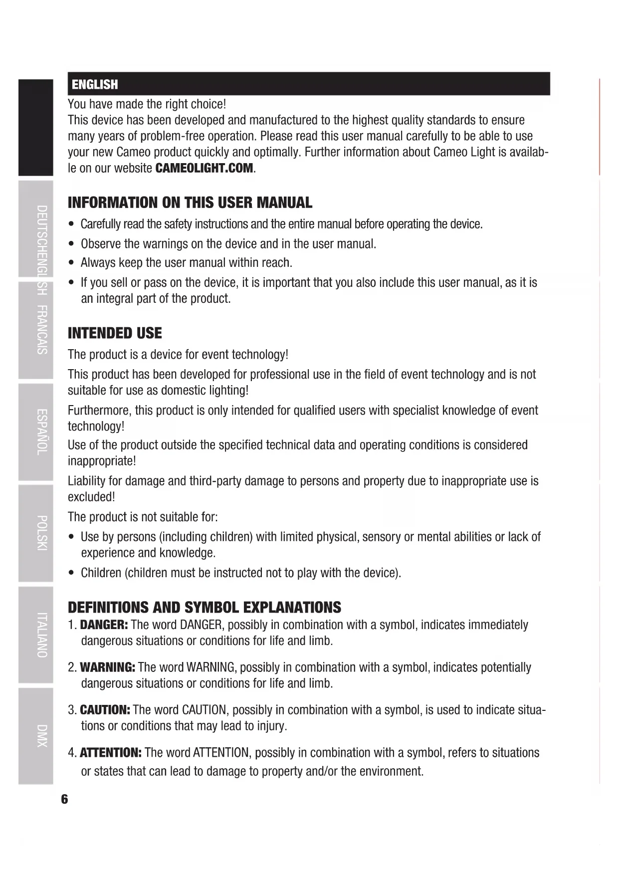
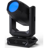
Black Opus 5PS+ optical mount with LED light and control panel (no visible text or symbols on device body)OPUS SP5 PLUS
PROFILE MOVING HEAD
CLOSP5PLUS
CONTENTS / INHALTSVERZEICHNIS / CONTENU / CONTENIDO / TREŚĆ / CONTENUTO
ENGLISH
INFORMATION ON THIS USER MANUAL 4
INTENDED USE 4
DEFINITIONS AND SYMBOL EXPLANATIONS 4
SAFETY INSTRUCTIONS 5
NOTES FOR MOBILE INDOOR DEVICES 8
INCLUDED 9
INTRODUCTION 9
CONNECTIONS, OPERATING AND DISPLAY ELEMENTS 10
OPERATION 13
SETUP AND INSTALLATION 20
CARE, MAINTENANCE AND REPAIR 21
TECHNICAL DATA 22
MINIMUM DISTANCE TO ILLUMINATED SURFACE 23
MINIMUM DISTANCE TO NORMALLY FLAMMABLE MATERIALS 23
DISPOSAL 24
MANUFACTURER'S DECLARATIONS 24
DEUTSCH
CONSEGNA INCLUSA 123
INTRODUZIONE 123
CONNESSIONI, ELEMENTI DI COMANDO E DI VISUALIZZAZIONE 124
FUNZIONAMENTO 127
You have made the right choice!
This device has been developed and manufactured to the highest quality standards to ensure many years of problem-free operation. Please read this user manual carefully to be able to use your new Cameo product quickly and optimally. Further information about Cameo Light is available on our website CAMEOLIGHT.COM.
INFORMATION ON THIS USER MANUAL
- Carefully read the safety instructions and the entire manual before operating the device.
- Observe the warnings on the device and in the user manual.
• Always keep the user manual within reach. - If you sell or pass on the device, it is important that you also include this user manual, as it is an integral part of the product.
INTENDED USE
The product is a device for event technology!
This product has been developed for professional use in the field of event technology and is not suitable for use as domestic lighting!
Furthermore, this product is only intended for qualified users with specialist knowledge of event technology!
Use of the product outside the specified technical data and operating conditions is considered inappropriate!
Liability for damage and third-party damage to persons and property due to inappropriate use is excluded!
The product is not suitable for:
- Use by persons (including children) with limited physical, sensory or mental abilities or lack of experience and knowledge.
- Children (children must be instructed not to play with the device).
DEFINITIONS AND SYMBOL EXPLANATIONS
- DANGER: The word DANGER, possibly in combination with a symbol, indicates immediately dangerous situations or conditions for life and limb.
- WARNING: The word WARNING, possibly in combination with a symbol, indicates potentially dangerous situations or conditions for life and limb.
- CAUTION: The word CAUTION, possibly in combination with a symbol, is used to indicate situations or conditions that may lead to injury.
- ATTENTION: The word ATTENTION, possibly in combination with a symbol, refers to situations or states that can lead to damage to property and/or the environment.

This symbol identifies hazards that can cause electric shock.

This symbol identifies hazardous areas or hazardous situations.

This symbol indicates hazards caused by hot surfaces.

This symbol indicates hazards caused by intense light sources.

This symbol indicates a device in which there are no user-replaceable parts.

This symbol indicates additional information on the operation of the product.
SAFETY INSTRUCTIONS

HAZARD:
- Do not open or modify the unit.
- If your device no longer functions properly, if liquids or objects get inside it or if it has been damaged in any other way, switch it off immediately and disconnect it from the mains. The device may be repaired only by authorised repair technicians.
- For devices of protection class 1, the protective conductor must be connected correctly. Never disconnect the protective conductor. Devices of protection class 2 do not have a protective conductor.
- Ensure that live cables are not kinked or otherwise mechanically damaged.
- Never bypass the unit fuse.

WARNING:
- The device may not be operated if it shows obvious signs of damage.
- The device may only be installed in a voltage-free state.
- If the mains cable of the device is damaged, do not operate the device.
- Permanently connected power cables may only be replaced by a qualified person.

ATTENTION:
- Do not operate the unit if it has been exposed to large temperature fluctuations (for example, after transport). Moisture and condensation can damage the device. Switch on the device only when it has reached room temperature.
- Make sure that the voltage and frequency of the mains supply correspond to the values indicated on the unit. If the device has a voltage selector switch, do not connect the device until it has been set correctly. Use only suitable power cables.

- To disconnect the unit from the mains at all poles, it is not sufficient to press the on/off switch on the unit.
- Make sure that the fuse used corresponds to the type printed on the unit.
- Make sure that appropriate measures have been taken against overvoltage (e.g. lightning strike).
- Observe the specified maximum output current on units with Power Out connection. Ensure that the total current consumption of all connected devices does not exceed the specified value.
- Replace pluggable mains cables only with original cables.

HAZARD:
- Danger of suffocation! Plastic bags and small parts must be kept out of reach of persons (including children) with reduced physical, sensory or mental capabilities.
- Danger from falling down! Make sure that the device is securely installed and will not fall down. Only use suitable stands or mounts (particularly for fixed installations). Ensure that accessories are properly installed and secured. Ensure that applicable safety regulations are observed.

WARNING:
- Use the device only in the manner intended.
- Operate the device only with the accessories recommended and intended by the manufacturer.
- During installation, observe the safety regulations applicable in your country.
- After connecting the unit, check all cable routes to avoid damage or accidents, e.g. due to tripping hazards.
- Always observe the specified minimum distance to normally flammable materials! Unless explicitly stated, the minimum distance is 0.3 m.
- Always observe the minimum distance to the illuminated surface that can be read on the device!

CAUTION:
- In the case of moving components such as mounting brackets or other moving components, there is a possibility of jamming.
- In the case of units with motor-driven components, there is a risk of injury from the movement of the unit. Sudden movement of the device can cause shock reactions.
- The housing surface of the device can become very hot during regular operation. Ensure that accidental touching of the housing is not possible. Always allow the lamp to cool sufficiently before removal, maintenance work and charging etc.

ATTENTION:
- Do not install or use the device in the vicinity of radiators, accumulators, stoves, or other heat sources. Ensure that the device is always installed in such a way that it is sufficiently cooled and cannot overheat.
- Do not place any ignition sources, such as burning candles, near the device.
- Ventilation openings must not be covered and fans must not be blocked.
- Use the original packaging or packaging provided by the manufacturer for transport.
- Avoid shock or impact to the unit.
- Observe the IP protection class as well as the ambient conditions such as temperature and humidity according to the specification.
7 Devices can be continuously further developed. In the event of deviating information on operating conditions, performance or other device properties between the user manual and the device labelling, the information on the device always takes priority. - The unit is not suitable for tropical climates and for operation above 2000 m above sea level.
- Unless explicitly stated, the unit is not suitable for operation in marine conditions.

CAUTION! IMPORTANT INFORMATION REGARDING LIGHTING PRODUCTS!
- Never look directly into the beam of light, not even for a short period of time.
- Never look into the beam of light using optical devices such as a magnifying glass.
- Stroboscopic effects may cause epileptic seizures in susceptible individuals!

SIGNAL TRANSMISSION BY RADIO (E.G. W-DMX OR AUDIO RADIO SYSTEMS):
The quality and performance of wireless signal transmissions generally depends on the ambient conditions.
The following factors can impact range and signal stability, for example:
Shielding (e.g. masonry, metal structures, water)
High volume of radio traffic (e.g. powerful wireless LAN networks)
Interference
Electromagnetic radiation (e.g. LED video screens, dimmers)
All range specifications refer to free-field application with visual contact and without interference!
The operation of transmission systems is subject to official regulations. These may vary from region to region and must be checked by the operator before use (e.g. radio frequency and transmission power).

WARNING: Devices with wireless signal transmission are not suitable for use in sensitive areas in which radio operation can lead to potential detrimental effects. These include:
- Hospitals, health centres or other healthcare facilities that provide patient treatment with skilled personnel and equipment.
• Hazardous areas Class I, II and III - Restricted areas
- Military facilities
- Aircraft or vehicles
- Areas where the use of mobile phones is prohibited

TRANSMISSION VIA W-DMX
WARNING: Ingeneral, wireless DMX transmission must not be used for applications with safety-related factors that could result in personal injury or property damage in the event of failure.
This applies in particular to moving scene or traverse structures, DMX-controlled motors/lifts or lifting devices for operating DMX-operated platform lifts, hydraulic systems or comparable moving components.
Furthermore, wireless DMX transmission must not be used to trigger flame or pyrotechnic devices, explosion-driven effects, or to control gas or liquid effects. These include CO2 cannons, confetti shooters, water effects or similar.

CAUTION! POTENTIAL DAMAGE FROM EXTERNAL LIGHT SOURCES!
Solar radiation, laser radiation and bundled light beams from other spotlights can damage the housing and internal components such as filters, gobo and colour wheels, motors, cables, belts, etc., as well as light sources!
Do not expose the unit and especially the lens opening to direct sunlight, laser radiation and bundled light beams from other spotlights during unpacking, installation, prolonged non-use and operation! Always point the lens opening towards the floor when the unit is not in use! For this purpose, also use the Sun Protection function, which can be activated via DMX command (see Device Settings channel in the DMX table). An integrated gyroscope sensor detects the position of use. Damage caused by external light sources is excluded from the manufacturer's warranty!

natural_image
Diagram of a vehicle under a sun with a diagonal line crossing it, no text or symbols present.

natural_image
Two radar equipment units crossed out by a diagonal line, no text or symbols present
NOTES FOR MOBILE INDOOR DEVICES
- Temporary operation! Event equipment is generally only designed for temporary operation.
- Continuous operation or permanent installation can impair the functioning of the device and cause premature ageing.
INCLUDED
Remove the product from the packaging and remove all packaging material.
Please check the completeness and integrity of the delivery and notify
Please contact your sales partner immediately after the purchase if the delivery is not complete or is damaged. The packaging includes:
▶ 1 x OPUS SP5 PLUS LED Moving Head
▶ 2 x Omega mounting bracket
1x Power cord
▶ User manual
INTRODUCTION
MOVING HEAD OPUS SERIES
CLOSP5PLUS
CONTROL FUNCTIONS:
34-channel and 50-channel DMX control (CLOSP5PLUS)
27-channel and 33-channel DMX control (CLOSP5PLUS with optional CLOSP5AM animation wheel module)
Art-Net
sACN
W-DMX TM
RDM-enabled
Master/slave operation
Standalone functions
FEATURES:
500 W High Efficiency LED. Framing Shutter Module. CMY + CTO colour blending Colour wheel with 7 brilliant colours + open and split colours. Gobo wheel 1 with 8 fixed gobos + open. Gobo wheel 2 with 7 rotating gobos + open (gobos interchangeable). 2 rotating prisms. Focusing and zoom function via DMX. Frosted filter and iris Strobe. Pan and tilt motors with 16-bit resolution. Battery-powered. Display for mains-independent setting. Automatic position correction. Temperature-controlled fans. 3- and 5-pole DMX connections. RJ45 network connections. Wireless DMX™ Neutrik powerCON TRUE1 mains connections IN and OUT. 2 Omega mounting brackets included. Operating voltage 100-240 V AC. Power consumption 800W. The spotlight features the RDM standard (Remote Device Management). Remote device management allows the user to view the status and configuration of RDM terminals via an RDM-capable controller.
ADDITIONAL PROPERTIES
The CLOSP5P moving head comes equipped with a 4-way framing shutter module. The 4-way framing shutter module can be interchanged with the CLOSP5AM animation wheel module. The software and corresponding DMX modes are upgraded automatically.
CONNECTIONS, OPERATING AND DISPLAY ELEMENTS

1 POWER IN
Neutrik powerCON TRUE1 mains input socket. Operating voltage 100–240 V AC/50–60 Hz. A suitable mains cable with powerCON TRUE1 plug is included.
2 POWER OUT
Neutrik powerCON TRUE1 mains output socket. Facilitates power supply to other CAMEO spotlights. Ensure that the total power consumption of all devices connected to the device does not exceed the given ampere (A) value.
3 FUSE
Fuse holder for 5 x 20 mm micro fuses. IMPORTANT NOTE: Replace the fuse only with one of the same type and rating. In the event of repeated fuse failure, please contact an authorised service centre.
4 DMX IN
Male 3-pin and 5-pin XLR sockets for connection of a DMX control device (e.g. DMX console).
5 DMX OUT
Female 3-pin or 5-pin XLR sockets for sending the DMX control signal.
6 NET IN
RJ45 network connector for connecting to an Art-Net or sACN network. Use CAT 5e or better cables to set up the network.
7 NET OUT
RJ45 network connector for connecting additional Art-Net or sACN-capable devices to the network. Use CAT 5e or better cables to set up the network.
8 ANTENNA FOR W-DMX™
The antenna for control via W-DMX ™ remains in the holder (= operating position) during operation.

9 PRESSURE SENSITIVE LC DISPLAY WITH ILLUMINATION
Thanks to the pressure-sensitive LC display, the device can be operated directly from the display (glove-compatible). The LCD display shows the currently activated mode (main display), the menu items in the selection menu and the numerical value or operating status in certain menu items. If there is no control signal to the device, the display starts flashing; the flashing stops as soon as a control signal is present (DMX and slave operation, ArtNet and sACN).
10 TOUCH-SENSITIVE CONTROLS
MODE - Pressing MODE (repeatedly) takes you one level up in the menu structure, to the main display.
UP ▲ and DOWN ▼ - Select the individual menu items in the main menu (DMX address, operating mode, etc.) and in the submenus.
ENTER – Starting from the main display, press ENTER to enter the main menu. In the main menu, press ENTER to access the menu level in which values can be changed. Confirm value changes by pressing ENTER.
LEFT ◀ and RIGHT ▶ - Use the control panels to change the value of a menu item, such as the DMX address, as desired.
11 USB INTERFACE
USB interface for updating the device firmware. In the Service menu, set the status for USB update to ON. When available, download the latest firmware from the product page at www.cameolight.com, unzip it and copy the files to a folder without special characters on a USB stick. Disconnect the Moving Head from the mains and all input connections (DMX / Ethernet), connect the USB stick to the USB interface and reconnect the Moving Head to the mains. The USB stick is automatically recognised and shown in the display. Now navigate to the corresponding folder on the USB stick and confirm with ON. The update procedure begins. Do not remove the USB stick or disconnect the Moving Head from the mains during the update procedure.
The battery-powered display can be activated, even if the device is not connected to the mains. To do this, press and hold MODE for approximately 3 seconds. You can now access device information to change and save system settings without mains connection. External control of the spotlight is not activated in this case. For this reason, the display shows that there is no DMX signal even if a DMX signal is available at the device.
12 PAN LOCK
Mechanical locking device used to prevent the rotation of the head in the horizontal direction during transport. Disconnect the unit from the mains, move the head parallel to the base (4 possible positions) and push the locking lever in the direction of the pan rotation axis to lock it in position. Unlock the device before startup.
13 TILT LOCK
Mechanical locking device used to prevent the rotation of the head in the vertical direction during transport (7 positions). Disconnect the unit from the mains and slide the locking lever in the direction of the tilt rotation axis, moving the head of the unit vertically until one of the 7 locking positions is found and the locking lever engages. Unlock the device before startup.

OPERATION
NOTES
As soon as the fixture is correctly connected to the mains, "Software Update Please Wait..." and the Cameo logo with information on the fixture model are shown in the display one after the other during the start-up process and the motor reset. After this process, the spotlight is ready for operation and the previously selected mode will be activated. On the one hand, the headlamp is operated with the help of the touch-sensitive control panels next to the display; on the other hand, the pressure-sensitive display (glove-compatible) itself can be used to reach all menu items and make settings intuitively as desired. Information on which control element in the display and which control panel next to the display have the same function can be found in the adjacent table. The following describes the operation using the control panels next to the display.
| Display | Bedienfeld | |
 | = |  |
 | = |  |
 | = |  |
 | = |  |
 | = |  |
 | = |  |
MAIN DISPLAY
The top line of the display shows whether and which control signal is present at the unit, the line below shows the currently activated operating mode (DMX Standard / Extended, Static, Auto, Slave) and the DMX start address or the corresponding operating mode (in the example DMX start address 001) is clearly visible in the middle. As soon as the control signal is interrupted, the characters in the display start flashing and "None" (no signal) is displayed behind "Signal" in the upper line. The display can be rotated 180irc by tapping the touch-sensitive control panel DOWN; if the display is already rotated 180irc , tap the control panel UP to return the display to the standard image. The display can also be rotated 180irc by pressing the "roof symbol" in the pressure-sensitive display.

flowchart
graph TD
    A["Display of the input signal"] --> B["DMX mode or operating mode"]
    B --> C["001"]
    C --> D["Information on the device model Back to main display = any position in the display or"]
    E["Signal:DMX"] --> F["User Mode:Extended"]
    G["Main menu"] --> H["Main menu"]
    I["Display battery status"] --> J["Rotate display by 180"]

CONTROL MENU (Control)
SETTING DMX START ADDRESS (DMX Address)
Starting from the main display, press ENTER to enter the main menu. Use the and controls to select the control menu Control and press ENTER. Use UP and DOWN to select the menu item "DMX Address" and confirm by pressing ENTER. Now set the desired DMX start address using the LEFT and RIGHT control panels and confirm with ENTER (highest value depends on the activated DMX mode). Press MODE twice to return to the main display, the selected DMX start address is now shown in large letters on the display when DMX mode is activated.


SET DMX MODE (DMX Mode)
Starting from the main display, press ENTER to enter the main menu. Use the and controls to select the control menu Control and press ENTER. Use UP and DOWN to select the menu item "DMX Mode" and confirm by pressing ENTER. Select the desired DMX mode again with UP and DOWN and confirm the selection with ENTER. Press MODE 2x to return to the main display, the selected DMX mode is now activated. Tables with the channel assignment of the different DMX modes can be found in these instructions under DMX CONTROL.


NETWORK SETTINGS (Network)
Starting from the main display, press ENTER to enter the main menu. Use the and controls to select the control menu Control and press ENTER. Use UP and DOWN to select the menu item "Network" and confirm by pressing ENTER. For information on the network settings, please refer to the table below. Confirm all network setting changes with ENTER.


| Network | |||
| Network Input | Activate / deactivate network input | OFF Network input deactivated | |
| ON Network input activated | |||
| Protocol Network protocol | ArtNET ArtNet Protocol | ||
| sACN sACN protocol | |||
| Address | Universe 1 - 256, Set IP address and subnet mask | Universe 000 - 255 | 000 to 255. Change value with LEFT and RIGHT, confirm with ENTER. |
| IP Address | Select block with LEFT and RIGHT, change value with UP and DOWN, confirm with ENTER. | ||
| IP Subnet Mask | Select block with LEFT and RIGHT, change value with UP and DOWN, confirm with ENTER. | ||
| DMX OUT | Output network signal via DMX OUT | OFF Do not output signal | |
| ON Output signal | |||
W-DMX SETTINGS (Wireless)
Starting from the main display, press ENTER to enter the main menu. Use the and controls to select the control menu Control and press ENTER. Use UP and DOWN to select the menu item "Wireless" and confirm by pressing ENTER. For information on the W-DMX settings, please refer to the table below. Confirm all changes to the settings with ENTER.


| Wireless | ||
| W-DMX | OFF Deactivate W-DMX | |
| ON Activate W-DMX | ||
| Operating (currently in beta status) | Receiver W-DMX module configured as receiver | |
| Transmitter W-DMX module configured as transmitter | ||
| Transmitting (currently in beta status) | G3 G3 transmission standard | |
| G4s G4S transmission standard | ||
| Link | Link | Pair with W-DMX devices. W-DMX must be enabled on all devices, and the pairing with a transmitter must be reset (Receive Reset) |
| Unlink Unpair | all devices | |
| Receive Reset | NO Do not reset transmitter pairing | |
| YES Reset transmitter pairing | ||
STAND ALONE MODES (Stand Alone)
Starting from the main display, press ENTER to enter the main menu. Use the and controls to select the control menu Control and press ENTER. Using and , now select the menu item "Stand Alone" and confirm by pressing ENTER. Now select one of the three stand-alone modes using the and controls and confirm with ENTER.

STANDALONE STATIC MODE (Static)
The Static mode allows PAN, Tilt, Dimmer, Strobe, Colour Wheel and Gobo Wheel etc. to be adjusted directly on the device with values between 000 to 255, similar to a DMX control unit. In this way, an individual scene can be created without an additional DMX controller. After you have selected the "Static" operating mode, as previously described under "STAND ALONE OPERATING MODES", the settings can be made as desired. The submenu items correspond to channels 1 to 50 in 50-channel extended DMX mode (see DMX CONTROL, select submenu item with UP and DOWN, change value with LEFT and RIGHT, confirm with ENTER). Press MODE repeatedly to return to the main display.

STAND ALONE OPERATION MODE AUTO PROGRAMS (Auto Prog)
The 4 different auto programmes (Program 1 - 4) each consist of fixed programmed head movements, gobo and colour changes etc., the running speed can be set separately. As previously described under "STAND ALONE OPERATING MODES", select the Auto operating mode, confirm with ENTER, select the desired Auto programme using UP and DOWN, confirm with ENTER and now change the value for the running speed from 000 to 100 as desired using LEFT and RIGHT. Confirm with ENTER. Press MODE repeatedly to return to the main display.


SLAVE MODE (Slave)
The slave operating mode is selected as previously described under item "STAND ALONE OPERATING MODES". Connect the slave unit and the master unit (same model, same software version) using a DMX cable (master DMX OUT - slave DMX IN) and activate one of the standalone modes Auto or Static in the master unit. The slave unit will now follow the master unit. Press MODE repeatedly to return to the main display.


SYSTEM SETTINGS (Settings)
Starting from the main display, press ENTER to enter the main menu. Select the Settings menu for the system settings using the UP and DOWN control panels and press ENTER.

This will take you to the submenu for setting the submenu items (see table, select with UP and DOWN, confirm with ENTER, change value or status with UP and DOWN, confirm with ENTER).
| Settings (bold = factory setting) | ||||
| Display | Display Settings | Reverse | OFF | No display rotation |
| ON | Display is rotated through 180°(e.g. for overhead installation) | |||
| Backlight | OFF | Deactivation of the display lighting after approx. 30 seconds of inactivity | ||
| ON D | display lighting permanently on | |||
| DMX fail | Operating status when DMX signal is interrupted | Black Activates blackout | ||
| Hold Last command is retained | ||||
| Car activates Auto mode | ||||
| Dimmer curve | Selecting the Dimmer curve | Linear | Light intensity increases linearly with DMX value | |
| Dimmer Curve | Selecting the Dimmer curve | Exponential | Light intensity can be finely adjusted at lower DMX values and broadly adjusted at higher DMX values | |
| Logarithmic | Light intensity can be broadly adjusted at lower DMX values and finely adjusted at higher DMX values | |||
| Dimmer curve | Light intensity can be finely adjusted at lower and higher DMX values and broadly adjusted at medium DMX values | |||
| LED Frequency | Configuration of LED PWM frequency | 650Hz, 1530Hz, 3600Hz, 12KHz, 25KHz | ||
| Pan / Tilt Device head settings | Pan reverse | OFF | Does not reverse pan direction | |
| ON R | Reverses pan direction | |||
| Tilt Reverse | OFF | Does not reverse tilt direction | ||
| ON R | Reverses tilt direction | |||
| Pan Angle | 630 | Pan angle 630° | ||
| 540 | Pan angle 540° | |||
| Feedback | OFF | Automatic position correction is disabled | ||
| ON | Automatic position correction is enabled | |||
| B.O. Moving | Automatic blackout for head movement | OFF No blackout during head movement | ||
| ON Blackout during head movement | ||||
| Fixture Type Device type: | Profile modules | |||
| Spot Module | ||||
| Fan Fan control | Car Automatic fan control | |||
| Fan Off | Deactivated fan with greatly reduced brightness | |||
| Constant Low | Constantly low fan speed with reduced brightness, if necessary | |||
| Constant Mid | Constant average fan speed with reduced brightness, if necessary | |||
| Constant High Constant | high fan speed | |||
DIMMER CURVES

DMX value

DMX value

DMX value

DMX value

SERVICEMENU
Starting from the main display, press ENTER to enter the main menu. Use the UP and DOWN control fields to select the Service menu and press ENTER.

This takes you to the submenu for editing the submenu items (select with UP and DOWN, confirm with ENTER, change value with LEFT and RIGHT, confirm with ENTER).
Calibrate - Calibrate the components with values from 000 to 255 (password 050).
Test Manual - Manual testing of the components with values from 000 to 255.
Reset Motor - Reset the motors. All = All motors, Pan&Tilt = Pan and Tilt motors,
Head Only = Motors in the unit head.
USB Update - Firmware update via USB interface. OFF = Block firmware update via USB
interface. ON = Allow firmware update via USB interface.
Factory Reset - Reset to factory settings.

DEVICE INFORMATION (Info)
Starting from the main display, press ENTER to enter the main menu. Use the and controls to select the information menu Info and press ENTER.

This will take you to the submenu for reading the device information (select with and, confirm with ENTER).
| System Info | |||
| Error info | Function error displayIf a fault is not corrected by a reset or restart, the defective unit must be repaired by an authorised service centre. | ||
| Temperature | Temperature display | Head xx°C/F° | |
| Base xx°C/F° | |||
| Unit | Temperature display in degreesCelsius or Fahrenheit | ||
| Runtime | Displays operating time | Total Time Displays total operating time in hours | |
| Current Time Displays the current operating time | |||
| Time PW | Enter the password for resetting the current operating time (Time PW = 050) | ||
| Clean Current Resets the current operating time | |||
| Firmware | Display of the firmware of the components 1U to 8U | Vx.xx | |
| Model Info | Information about the unit version | Profiles Modules | Module with framing shutter |
| Spot Module Module with animation wheel | |||
SETUP AND INSTALLATION
Thanks to its integrated rubber feet, the spotlight can be positioned in a suitable location on a firm and level surface. Traverse installation can be achieved with the help of two Omega brackets, which are attached to the base of the device (A). 2 x Omega brackets are included. Suitable beam clamps are available as an option. Ensure firm connections and secure the spotlight to the securing lug (B) with a suitable safety cable.

IMPORTANT NOTE: Overhead installation requires extensive experience, including calculation of working load limits, installation materials used and regular safety checks of all installation materials and fixtures. If you do not have these qualifications, do not attempt to perform an installation yourself. Refer instead to a qualified professional.

CARE, MAINTENANCE AND REPAIR
In order to ensure the long-term, proper functioning of the device, it must be regularly cleaned and, if necessary, maintained. The maintenance requirement depends on the intensity of use and the environment in which it is used. We generally recommend a visual inspection before each operation. Furthermore, we recommend carrying out all the applicable maintenance measures specified below once every 500 operating hours or, in the case of a lower intensity of use, at the latest after one year. Warranty claims may be limited in the event of defects resulting from inadequate maintenance.
CARE (carried out by user)

WARNING! Before carrying out any care or maintenance, the power supply – and, if possible, all device connections – must be disconnected.

PLEASE NOTE! Improper care can lead to impairment of the device or even its destruction.
- Housing surfaces must be cleaned with a clean, damp cloth. Make sure that no moisture can penetrate the device.
- Air inlets and outlets must be regularly cleaned of dust and dirt. If compressed air is used, make sure that damage to the device is prevented (e.g. fans must be blocked in this case).
- Lines and plug contacts must be cleaned regularly and dust and dirt must be removed.
- In general, no cleaning agents or abrasive agents may be used, otherwise the surface finish may be damaged.
- Devices must generally be stored dry and protected from dust and dirt.
MAINTENANCE AND REPAIR (by qualified personnel only)

HAZARD! There are live components in the device. Even after disconnecting the mains connection, there may still be residual voltage in the device, for example, due to charged capacitors.

PLEASE NOTE! There are no user-serviceable assemblies in the device.

PLEASE NOTE! Maintenance and repair work may only be carried out by qualified specialist personnel authorised by the manufacturer. If in doubt, consult the manufacturer.

PLEASE NOTE! Improperly performed maintenance work may affect warranty claims.
TECHNICAL DATA
| Product number: CLOSP5PLUS | |
| Product type: LED moving light | |
| Type: Moving Head | |
| Number of lamps: 1 | |
| Type of lamp: 500W High Efficiency LED | |
| Colour temperature lamp: | Cold white 6600K |
| CRI: >70 | |
| LED PWM frequency: 650Hz, 1530Hz, 3600Hz, 12kHz, 25kHz (adjustable) | |
| Colour blend function: CMY + CTO | |
| Number of colours: Colour wheel: | 7 + open and split colours |
| Number of gobos: 15 + open (8 fixed + 7 rotating) | |
| Gobo size: | ∅ outside 22.9mm (-0.2 / +0.1mm), ∅ motif 19mm, material thickness 1.1mm (glass) |
| Beam angle: 6° - 42° | |
| DMX input: | 3-pin XLR male5-pin XLR male |
| DMX output: | 3-pin XLR female5-pin XLR female |
| Network connections. RJ45 IN and OUT (lockable) | |
| DMX mode: 34-channel, 50-channel | |
| DMX functions: | Pan/Tilt, Pan/Tilt fine, Dimmer, Dimmer fine, Multifunctional strobe, Cyan, Cyan fine, Magenta, Magenta fine, Yellow, Yellow fine, CTO, CTO fine, Colour wheel, Colour wheel rotation, Gobo wheel 1, Gobo 1 rotation, Gobo 1 rotation fine, Gobo wheel 1 rotation, Gobo 1 shake, Gobo wheel 2, Gobo wheel 2 rotation, Gobo 2 shake, Zoom, Zoom fine, Focus, Focus fine, Iris, Prism, Prism Rotation, Frost, Blade 1 - 4, Blade 1 - 4 fine, Shape Rotation, Shape Rotation fine, Pan/Tilt Macros, Pan/Tilt Speed, Dimmer Curve, System Settings |
| Standalone functions: Automatic programmes 1-4, static mode, master/slave operation | |
| System settings: | Wireless Setting, Display Reverse, Display Lighting On/Off, DMX Fail, Dimmer Curve, Pan Reverse, Tilt Reverse, Pan Angle, Feedback, Fan Setting, Movement Blackout, Test, Motor Reset, Factory Reset, Network Settings |
| Control: | DMX512, RDM enabled, W-DMXTM (Receiver), Art-Net, sACN |
| PAN angle: | 540°/630° |
| TILT angle: | 270° |
| Operating controls: | Touch-sensitive controls BACK, ENTER, UP, DOWN, LEFT, RIGHT, pressure-sensitive graphic colour LCD display (glove-compatible) |
| Display elements: | Illuminated graphic colour LC display, battery-powered for mains-in-dependent system settings |
Operating voltage: 100–240 V AC / 50–60 Hz
Power consumption: 800 W
Luminous flux: 22000 lm
Power supply connection: Neutrik TRUE1 input and output (output max. 4A)
Fuse: T8AL / 250V (5 x 20mm)
Ambient operating temperature: -15ircC to 40ircC
Relative air humidity: < 85%, non-condensing
Minimum distance to illuminated surface: 3 m
Minimum distance to normally flammable materials: 0.5 m
Housing material: Metal, ABS
Housing colour: Black
Housing cooling: Heatpipe cooling system plus temperature controlled fans
Dimensions (W x H x D, without bracket): 397 x 741.5 x 285mm
Weight: 27.8kg
Additional features: 1m mains cable with TRUE1 plug and 2 Omega mounting brackets included
MINIMUM DISTANCE TO ILLUMINATED SURFACE

This symbol with distance information in metres (m) indicates the minimum distance of the luminaire to the illuminated surface. In this example, the distance is 0.5m. Please refer to the technical data in this manual and the imprint on the unit casing for the value valid for this unit!
MINIMUM DISTANCE TO NORMALLY FLAMMABLE MATERIALS

This symbol with distance indication in metres (m) indicates the minimum distance of the appliance to normally flammable materials. In this example, the distance is 0.5m. Please refer to the technical data in this manual for the value valid for this unit!
DISPOSAL

PACKAGING:
- Packaging can be fed into the reusable material cycle using the usual disposal methods.
- Please separate the packaging in accordance with the disposal laws and recycling regulations in your country.

DEVICE:
- This appliance is subject to the European Directive on Waste Electrical and Electronic Equipment as amended. WEEE Directive Waste Electrical and Electronic Equipment. Old appliances do not belong in household waste. The old device must be disposed of via an approved disposal company or a municipal disposal facility. Please observe the applicable regulations in your country!
- Observe all disposal laws applicable in your country.
- As a private customer, you can obtain information on environmentally-friendly disposal options from the seller of the product or the appropriate regional authorities.
MANUFACTURER'S DECLARATIONS
Manufacturer's warranty & limitation of liability
Adam Hall GmbH, Adam-Hall-Str. 1, D-61267 Neu Anspach /
E-mail: Info@adamhall.com / +49 (0)6081 / 9419-0
Our current warranty conditions and limitation of liability can be found at:
https://cdn-shop.adamhall.com/media/pdf/Manufacturers-Declarations-CAMEO_DE_EN_ES_FR.pdf In case of service, please contact your sales partner.
CE conformity
Adam Hall GmbH hereby confirm that this product meets the following guidelines (where applicable):
Low-Voltage Directive (2014/35/EU)
EMC Directive (2014/30/EU)
RoHS (2011/65/EU)
RED (2014/53/EU)
EC Declaration of Conformity
Declarations of conformity for products subject to the LVD, EMC, RoHS Directive can be requested from info@adamhall.com
Declarations of conformity for products subject to RED can be downloaded from www.adamhall.com/compliance/.
Subject to misprints and errors, as well as technical or other modifications!
DEUTSCH
natural_image
Symbolic illustration of a mechanical device with a sun above it and a diagonal line below, no text or labels present.

natural_image
Diagram showing two identical mechanical devices connected by a diagonal line, enclosed in a circle (no text or symbols)
HINWEISE FÜR ORTSVERÄNDERLICHE INDOOR-GERÄTE
9 DRUCKEMPFINDLICHES LC-DISPLAY MIT BELEUCHTUNG
https://cdn-shop.adamhall.com/media/pdf/Manufacturers-Declarations-CAMEO_DE_EN_ES_FR.pdf
DANGER : Devices with wireless signal transmission are not suitable for use in sensitive areas in which radio operation can lead to potential detrimental effects. Citons notamment :
natural_image
Symbolic diagram of a mechanical device with a yellow star above it and a diagonal line below, no text or labels present.

natural_image
Diagram showing two identical devices connected by a diagonal line, enclosed in a circle (no text or symbols)
NOTES POUR LES APPAREILS MOBILES D'INTÉRIEUR
9 AFFICHEUR LC TACTILE RÉTRO-ÉCLAIRÉ
PARAMÈTRES W-DMX (Wireless)

MODE ESCLAVE (Slave)
ENTRETIEN, MAINTENANCE ET RÉPARATIONS
https://cdn-shop.adamhall.com/media/pdf/Manufacturers-Declarations-CAMEO_DE_EN_ES_FR.pdf
Directive CEM (2014/30/UE)
RoHS (2011/65/EU)
RED (2014/53/EU)
ADVERTENCIA: Devices with wireless signal transmission are not suitable for use in sensitive areas in which radio operation can lead to potential detrimental effects. Entre las zonas sensibles están:
natural_image
Symbolic illustration of a mechanical device with a sun above it and a diagonal line below, no text or labels present.

natural_image
Diagram showing two identical devices with a diagonal line crossing, enclosed in a circle (no text or symbols)
NOTAS PARA LOS EQUIPOS PORTÁTILES QUE SE INSTALAN EN INTERIORES

MODO ESCLAVO (Slave)
natural_image
Symbolic diagram of a vehicle under a sun, no text or labels present

natural_image
Diagram showing two identical devices connected by a diagonal line, enclosed in a circle (no text or symbols)
UWAGI DOTYCZĄCE MOBILNYCH URZĄDZEŃ WEWNETRZNYCH
9 CZUŁY NA NACISK WYŚWIETLACZ LCD Z PODŚWIETLENIEM
USTAWIENIA W-DMX (Wireless)

TRYB SLAVE (Slave)
KONFIGURACJA I INSTALACJA
PIELEGNACJA, KONSERWACJA I NAPRAWA
https://cdn-shop.adamhall.com/media/pdf/Manufacturers-Declarations-CAMEO_DE_EN_ES_FR.pdf
AVVERTENZA: Devices with wireless signal transmission are not suitable for use in sensitive areas in which radio operation can lead to potential detrimental effects. Queste zone includono:
natural_image
Symbolic illustration of a mechanical device with a sun above it and a diagonal line below, no text or labels present.

natural_image
Diagram showing two radar units connected by a diagonal line, enclosed in a circle (no text or symbols)
NOTE PER I DISPOSITIVI MOBILI PER INTERNI
PROPRIETÀ AGGIUNTIVE
9 DISPLAY LC SENSIBILE ALLA PRESSIONE CON ILLUMINAZIONE

MODALITÀ SLAVE (Slave)

- OPUS SP5 PLUS
- CONTENTS / INHALTSVERZEICHNIS / CONTENU / CONTENIDO / TREŚĆ / CONTENUTO
- ENGLISH
- DEUTSCH
- INFORMATION ON THIS USER MANUAL
- INTENDED USE
- DEFINITIONS AND SYMBOL EXPLANATIONS
- SAFETY INSTRUCTIONS
- HAZARD:
- WARNING:
- ATTENTION:
- CAUTION:
- CAUTION! IMPORTANT INFORMATION REGARDING LIGHTING PRODUCTS!
- SIGNAL TRANSMISSION BY RADIO (E.G. W-DMX OR AUDIO RADIO SYSTEMS):
- TRANSMISSION VIA W-DMX
- CAUTION! POTENTIAL DAMAGE FROM EXTERNAL LIGHT SOURCES!
- NOTES FOR MOBILE INDOOR DEVICES
- INCLUDED
- INTRODUCTION
- CONTROL FUNCTIONS:
- FEATURES:
- ADDITIONAL PROPERTIES
- CONNECTIONS, OPERATING AND DISPLAY ELEMENTS
- POWER IN
- POWER OUT
- FUSE
- DMX IN
- DMX OUT
- NET IN
- NET OUT
- ANTENNA FOR W-DMX™
- PRESSURE SENSITIVE LC DISPLAY WITH ILLUMINATION
- TOUCH-SENSITIVE CONTROLS
- USB INTERFACE
- PAN LOCK
- TILT LOCK
- OPERATION
- NOTES
- MAIN DISPLAY
- CONTROL MENU (Control)
- SETTING DMX START ADDRESS (DMX Address)
- SET DMX MODE (DMX Mode)
- NETWORK SETTINGS (Network)
- W-DMX SETTINGS (Wireless)
- STAND ALONE MODES (Stand Alone)
- STANDALONE STATIC MODE (Static)
- STAND ALONE OPERATION MODE AUTO PROGRAMS (Auto Prog)
- SLAVE MODE (Slave)
- SYSTEM SETTINGS (Settings)
- DIMMER CURVES
- SERVICEMENU
- DEVICE INFORMATION (Info)
- SETUP AND INSTALLATION
- CARE, MAINTENANCE AND REPAIR
- CARE (carried out by user)
- MAINTENANCE AND REPAIR (by qualified personnel only)
- MINIMUM DISTANCE TO ILLUMINATED SURFACE
- MINIMUM DISTANCE TO NORMALLY FLAMMABLE MATERIALS
- DISPOSAL
- PACKAGING:
- DEVICE:
- MANUFACTURER'S DECLARATIONS
- Manufacturer's warranty & limitation of liability
- CE conformity
- EC Declaration of Conformity
- HINWEISE FÜR ORTSVERÄNDERLICHE INDOOR-GERÄTE
- DRUCKEMPFINDLICHES LC-DISPLAY MIT BELEUCHTUNG
- NOTES POUR LES APPAREILS MOBILES D'INTÉRIEUR
- AFFICHEUR LC TACTILE RÉTRO-ÉCLAIRÉ
- PARAMÈTRES W-DMX (Wireless)
- MODE ESCLAVE (Slave)
- ENTRETIEN, MAINTENANCE ET RÉPARATIONS
- NOTAS PARA LOS EQUIPOS PORTÁTILES QUE SE INSTALAN EN INTERIORES
- MODO ESCLAVO (Slave)
- UWAGI DOTYCZĄCE MOBILNYCH URZĄDZEŃ WEWNETRZNYCH
- CZUŁY NA NACISK WYŚWIETLACZ LCD Z PODŚWIETLENIEM
- USTAWIENIA W-DMX (Wireless)
- TRYB SLAVE (Slave)
- KONFIGURACJA I INSTALACJA
- PIELEGNACJA, KONSERWACJA I NAPRAWA
- NOTE PER I DISPOSITIVI MOBILI PER INTERNI
- PROPRIETÀ AGGIUNTIVE
- DISPLAY LC SENSIBILE ALLA PRESSIONE CON ILLUMINAZIONE
- MODALITÀ SLAVE (Slave)
Brand : Cameo
Model : OPUS SP5 Plus
Category : Lamp