LUXIS FC - Lamp Cameo - Free user manual and instructions
Find the device manual for free LUXIS FC Cameo in PDF.

| Brand | Cameo |
| Model | LUXIS FC |
| Product type | Professional LED PAR projector |
| Light source | 6-in-1 RGBALC COB LED, 200 W |
| Luminous flux | 8536 lm |
| Beam angle (interchangeable) | 9°/16°, 21°/29°, 51°/63° |
| CRI | > 94 |
| Control modes | DMX (3/5-pin), RDM, W-DMX (option), standalone, master/slave, EZ remote control |
| DMX modes | 1 CH, 3 CH, 5 CH, 6 CH, 7 CH, 9 CH, 10 CH, 12 CH, 16 CH, 20 CH |
| Power supply | 100-240 V AC, 50/60 Hz |
| Max. power consumption | 280 W |
| Fuse | T4A (5x20 mm) |
| Weight | 7.0 kg |
| Dimensions (hanging) | 466 mm x 302 mm x 216 mm (h/w/d) |
| Dimensions (floor vertical) | 430 mm x 281 mm x 302 mm |
| Protection rating | IP20 (indoor) |
| Ambient temperature | -10°C to 40°C |
| Cooling | Fan (Off, Constant High/Medium/Low, Auto) |
| Minimum distance from illuminated surface | 0.5 m |
| Minimum distance from flammable materials | 0.5 m |
| Delivery contents | Projector, 9°, 21°, 51° lenses, filter frame, TV spigot 16 mm, power cable, manual |
| Maintenance | Cleaning of surfaces and air vents, cables and connectors |
| Safety | Do not open, do not look directly at the beam, risk of burns, installation by professional |
| Spare parts and repairability | Lenses, filter frame, fuse, cable, iDMX stick (option). Repair by qualified personnel only. |
Frequently Asked Questions - LUXIS FC Cameo
User questions about LUXIS FC Cameo
0 question about this device. Answer the ones you know or ask your own.
Ask a new question about this device
Download the instructions for your Lamp in PDF format for free! Find your manual LUXIS FC - Cameo and take your electronic device back in hand. On this page are published all the documents necessary for the use of your device. LUXIS FC by Cameo.
USER MANUAL LUXIS FC Cameo
natural_image
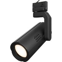
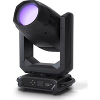
Black industrial lamp with purple laser beam, mounted on a support frame (no text or symbols visible)LUXIS® FC
FULL COLOUR LED PAR 200 W RGBALC
CLLUXISFC
CONTENTS / INHALTSVERZEICHNIS / CONTENU / CONTENIDO / TREŚĆ / CONTENUTO
ENGLISH
INFORMATION ON THIS USER MANUAL 6
INTENDED USE 6
DEFINITIONS AND SYMBOL EXPLANATIONS 6
SAFETY INSTRUCTIONS 7
NOTES FOR MOBILE INDOOR DEVICES 10
INCLUDED 10
INTRODUCTION 10
CONNECTIONS, OPERATING AND DISPLAY ELEMENTS 11
OPERATION 13
OPTIONAL ACCESSORIES 25
INSTALLING/REMOVING THE INTERCHANGEABLE LENS 25
MOUNTING THE FILTER FRAME OR BARNDOOR 26
SETUP AND INSTALLATION 28
SPIN16 TV SPIGOT 29
CARE, MAINTENANCE AND REPAIR 29
DIMENSIONS 30
TECHNICAL DATA 31
MINIMUM DISTANCE TO ILLUMINATED SURFACE 32
MINIMUM DISTANCE TO NORMALLY FLAMMABLE MATERIALS 32
DISPOSAL 32
MANUFACTURER'S DECLARATIONS 33
DEUTSCH
This device has been developed and manufactured to the highest quality standards to ensure many years of problem-free operation. Please read this user manual carefully to be able to use your new Cameo product quickly and optimally. Further information about Cameo Light is available on our website CAMEOLIGHT.COM.
INFORMATION ON THIS USER MANUAL
- Carefully read the safety instructions and the entire manual before operating the device.
- Observe the warnings on the device and in the user manual.
• Always keep the user manual within reach. - If you sell or pass on the device, it is important that you also include this user manual, as it is an integral part of the product.
INTENDED USE
The product is a device for event technology!
This product has been developed for professional use in the field of event technology and is not suitable for use as domestic lighting!
Furthermore, this product is only intended for qualified users with specialist knowledge of event technology!
Use of the product outside the specified technical data and operating conditions is considered inappropriate!
Liability for damage and third-party damage to persons and property due to inappropriate use is excluded!
The product is not suitable for:
- Use by persons (including children) with limited physical, sensory or mental abilities or lack of experience and knowledge.
- Children (children must be instructed not to play with the device).
DEFINITIONS AND SYMBOL EXPLANATIONS
- HAZARD: The word HAZARD, possibly in combination with a symbol, indicates situations in which there is an immediate danger or risk of potentially fatal injury.
- WARNING: The word WARNING, possibly in combination with a symbol, indicates situations in which there is an immediate danger or risk of potentially fatal injury.
- CAUTION: The word CAUTION, possibly in combination with a symbol, indicates situations or conditions that could result in injury.
- ATTENTION: The word ATTENTION, possibly in combination with a symbol, indicates situations or conditions that could result in damage to property and/or the environment.

This symbol identifies hazards that can cause electric shock.

This symbol identifies hazardous areas or hazardous situations.

This symbol indicates hazards caused by hot surfaces.

This symbol indicates hazards caused by intense light sources.

This symbol indicates a device in which there are no user-replaceable parts.

This symbol indicates additional information on the operation of the product.
SAFETY INSTRUCTIONS
HAZARD:
- Do not open the device and do not perform any modifications.
- If your device no longer functions properly, if liquids or objects get inside it or if it has been damaged in any other way, switch it off immediately and unplug it from the power source. The device may be repaired only by authorised repair technicians.
- For devices of protection class 1, the protective conductor must be connected correctly. Never disconnect the protective conductor. Devices of protection class 2 do not have a protective conductor.
- Ensure that live cables are not kinked or otherwise mechanically damaged.
- Never bypass the device fuse.
WARNING:
- The device may not be operated if it shows obvious signs of damage.
- The device may only be installed in a voltage-free state.
- If the device's power cable is damaged, the device may not be used.
- Permanently connected power cables may only be replaced by a qualified person.
CAUTION:
- Do not switch on the device if it has been exposed to extreme temperature fluctuations (for example, following transport). Moisture and condensation can damage the device. Switch on the device only when it has reached room temperature.
- Ensure that the voltage and frequency of the mains supply match the values specified on the device. If the device has a voltage selector switch, do not connect the device until it has been set correctly. Use only suitable power cables.
- To disconnect the device from the mains on all poles, it is not sufficient to press the on/off switch on the device.
- Make sure that the fuse used corresponds to the type printed on the device.
- Ensure that suitable measures have been taken against overvoltage (e.g. lightning strikes).
- Observe the specified maximum output current on devices with a Power Out connection. Ensure that the total current consumption of all connected devices does not exceed the specified value.
- Replace plug-in power cables with original cables only.

HAZARD:
- Choking hazard! Plastic bags and small parts must be kept out of reach of persons (including children) with reduced physical, sensory or mental capabilities.
- Risk of falling! Make sure that the device is securely installed and will not fall down. Only use suitable stands or mounts (particularly for fixed installations). Ensure that accessories are properly installed and secured. Ensure that applicable safety regulations are observed.

WARNING:
- Use the device in the prescribed manner only.
- Operate the device using only accessories of the type recommended and supplied by the manufacturer.
- Observe safety regulations applicable in your country during installation.
- After connecting the device, ensure that all cables are routed so as to avoid damage or accidents, such as from tripping.
- Always observe the specified minimum distance to normally flammable materials! Unless explicitly stated, the minimum distance is 0.3 m.

CAUTION:
- Moving components such as mounting brackets may become jammed.
- In the case of devices with motor-driven components, there is a risk of injury due to the movement of the device. Sudden movement of the device can cause shock reactions.
- The housing surface of the device can become very hot during regular operation. Ensure that accidental touching of the housing is not possible. Always allow the device to cool sufficiently before removal, maintenance work and charging etc.

CAUTION:
- Do not install or use the device in the vicinity of radiators, accumulators, stoves, or other heat sources. Ensure that the device is always installed in such a way that it is sufficiently cooled and cannot overheat.
- Do not place any ignition sources, such as burning candles, near the device.
- Ventilation openings must not be covered and fans must not be blocked.
- For transport, use the original packaging or packaging provided by the manufacturer.
- Avoid any impacts to or shaking of the device.
- Observe the IP rating and the ambient conditions such as temperature and humidity according to the specifications.
- Devices can be continuously further developed. In the event of deviating information on operating conditions, performance or other device properties between the user manual and the device labelling, the information on the device always has priority.
- The device is not suitable for tropical climate zones or for operation over 2,000 m above sea level.
- Unless explicitly stated, the device is not suitable for operation under marine conditions.

PLEASE NOTE:
For conversion or retrofit sets or accessories provided by the manufacturer, it is essential to observe the instructions included.
CAUTION! IMPORTANT INFORMATION REGARDING LIGHTING PRODUCTS!
- Never look directly into the beam of light, not even for a short period of time.
- Never look into the beam of light using optical devices such as a magnifying glass.
- Stroboscopic effects may cause epileptic seizures in susceptible individuals!


- Permanently installed lamps are built into these lighting units. These may not be replaced by the user. The lamps contained in this lighting unit may only be replaced by the manufacturer, its service partner, or a similarly qualified person.
NOTES FOR MOBILE INDOOR DEVICES

- Temporary operation! Event equipment is generally only designed for temporary operation.
- Continuous operation or permanent installation can impair the functioning of the device and cause premature ageing.
INCLUDED
Remove the product from the packaging and remove all packaging material.
Please check the completeness and integrity of the delivery and notify your distribution partner immediately after purchase if the delivery is not complete or if it is damaged.
Product includes:
1x LUXIS FC spotlight
▶ 1x interchangeable lens 9° (pre-assembled)
▶ 1x interchangeable lens 21°
▶ 1x interchangeable lens 51°
▶ 1x filter frame (pre-assembled)
▶ 1x SPIN16 16 mm TV spigot (pre-assembled)
1x power cable
▶ User manual
INTRODUCTION
LED PAR with 200 W RGBALC COB LED
CLLUXISFC
CONTROL FUNCTIONS:
1 CH DIM UC1, 3 CH Presets+D, 3 CH RGB, 5 CH RGB+D, 6 CH Direct, 9 CH Direct Control, 9 CH Direct+D, 7 CH RGB-CTC, 12 CH Direct-CCT, 10 CH HSI-CTC, 12 CH 16Bit, 16 CH 16Bit Direct, 20 CH Full Access DMX Control
Master/slave operation
Standalone functions
W-DMX™ optional
FEATURES:
200W 6in1 RGBALC COB LED. DMX512. W-DMX™ optional. 5- and 3-pin DMX connections. Spin16 folding TV spigot included. Quicklight via rotary-push encoder. Operating voltage: 100–240 V AC.
The spotlight features the RDM standard (Remote Device Management). Remote device management allows the user to view the status and configuration of RDM terminals via an RDM-capable controller.
CONNECTIONS, OPERATING AND DISPLAY ELEMENTS

text_image
10 SAFETY cameo® 7 8 MENU ENTER UP DOWN No User-replacable Parts Inside LUXIS® FC DMX IN DMX IN DMX OUT DMX OUT IDMX STICK 6 CAUTION MAX OUT CURRENT: 12 A FAE OF ELECTRIC Device 35-40-07-18 FUSE T4 A 250 V POWER IN POWER OUT CE UK CA POWER CONSUMPTION: 280 W 100 - 240 V AC 50/60 Hz Camero® is a registered brand of the Adam Hall Group Adam Hall GmbH Adam-Hall-Sitzl 61767 Neu-Amsch Germany I Designes and engineered in Germany, assembled in PRCI www.adamhall.com. Adam Hall Ltd. The Seabbed Business Centre SS3 SQY Essex I United Kingdom1 POWER IN
TRUE1-compatible mains input socket. Operating voltage 100–240 V AC/50–60 Hz. A suitable mains cable with TRUE1 compatible plug is included.
2 POWER OUT
TRUE1-compatible mains output socket. Facilitates power supply to other CAMEO lights. Ensure that the total power consumption of all devices connected to the device does not exceed the given ampere (A) value.
3 FUSE
Fuse holder for 5 x 20 mm fuses. IMPORTANT: Replace the fuse only with a fuse of the same type and value. In the event of repeated fuse failure, please contact an authorised service centre.
4 DMX IN
Male 3-pin and 5-pin XLR sockets for connection of a DMX control device (e.g. DMX console). Only use the ports alternatively.
5 DMX OUT
Female 3-pin or 5-pin XLR sockets for sending the DMX control signal. Only use the ports alternatively.
6 IDMX STICK
Connection for the optional iDMX stick for W-DMX ^TM connection (plug in the iDMX stick with the antenna facing upwards). When the spotlight is controlled via an iDMX stick, the control signal is transmitted via DMX OUT. The iDMX stick and DMX IN are only to be used alternatively.
7 OLED DISPLAY
The OLED display shows the currently activated mode (main display), the menu items in the menu and the numerical value or operating mode in certain menu items. If there is no input for approx. 30 seconds, the display automatically returns to the main display. Note regarding the main display in operating modes with external control: As soon as the control signal is interrupted, the characters in the display begin to flash. When there is a control signal again, the flashing stops. Briefly pressing UP when in the main display rotates the display by 180^ .
8 CONTROL BUTTONS
MENU – Press MENU to access the main menu. Press again or repeatedly to return to the main display. Pressing MENU without confirming a value or status change with ENTER restores the previously confirmed value or status.
ENTER – Press ENTER to access the menu levels to make value changes and use ENTER to access the submenus. Confirm value or status changes by pressing ENTER.
UP and DOWN – Select individual menu items in the main menu (DMX start address, DMX operating mode etc.) and in the submenus. Change the status or a value in a menu item, such as the DMX start address.
9 ROTARY-PUSH ENCODER
Four different spotlight modes are available as direct access for quick and easy adjustment of the spotlight without an external controller. These can be selected in the Encoder Mode menu item (Dimmer UC1, CCT, HSI, Direct LED).
If one of the DMX modes is activated and there is no DMX signal on the device, the default mode can be used with the encoder. Rotate or press the encoder to activate the mode. Change a numerical value (e.g. dimmer) by turning the encoder. If the preset mode has multiple channels, press the encoder to go to the next channel, etc.
If “Disabled” is selected in the Encoder Mode menu item, none of the four spotlight modes are available for direct access and the encoder is used to navigate in the menu.
10 SAFETY
Securing lug for attaching the spotlight.
OPERATION
PLEASE NOTE
As soon as the spotlight is correctly connected to the power supply, the following are displayed in succession: “Update wait ...” (for service purposes only), “Welcome to Cameo”, the model name and the software version. After this process, the spotlight is ready for operation and the previously activated operating mode is launched.
The main display is activated automatically if no input is made within approximately 30 seconds. To navigate one level up in the submenus, briefly press MENU.
- If one of the DMX operating modes is activated and there is no DMX signal to the DMX input or the iDMX stick, the characters on the display begin to flash.
- Briefly pressing UP when in the main display rotates the display by 180^ .
- To quickly change a value, such as the DMX start address, press and hold UP or DOWN.
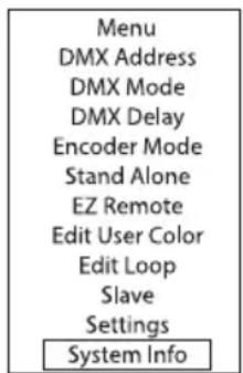
SET DMX START ADDRESS (DMX Address)
Starting from the main display, press MENU to enter the main menu. Now use UP and DOWN to select the menu item DMX Address and confirm with ENTER. Using the UP and DOWN buttons, configure the desired DMX start address and press ENTER to confirm (highest value dependent upon activated DMX mode).

text_image
Menu DMX Address DMX Mode DMX Delay Encoder Mode Stand Alone EZ Remote Edit User Color Edit Loop Slave Settings System Info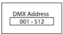

CONFIGURING DMX MODE (DMX Mode)
Starting from the main display, press MENU to enter the main menu. Now use UP and DOWN to select the menu item DMX Mode and confirm with ENTER. Use UP and DOWN again to select the desired DMX operating mode and confirm with ENTER (DMX operating modes with DMX delay channel are identified with 'D'). Tables with the channel assignments can be found in these instructions under DMX CONTROL.

text_image
Menu DMX Address DMX Mode DMX Delay Encoder Mode Stand Alone EZ Remote Edit User Color Edit Loop Slave Settings System Info
text_image
DMX Mode 1 CH DIM UC1 3 CH Presets+D 3 CH RGB 5 CH RGB+D 6 CH Direct 9 CH Direct Ctrl 9 CH Direct+D 7 CH RGB-CCT 12 CH Direct-CCT 10 CH HSI-CCT 12 CH 16Bit 16 CH 16Bit Dir 20 CH Full AccessDMX DELAY
The DMX Delay function is a simple way to create a running light effect with a large number of spotlights that are all the same model and that are all running the same software version. This is otherwise only achievable with a suitable DMX controller and time-consuming programming. All the spotlights used (same models, same software version) are set to the same DMX operating mode with DMX delay channel and controlled via the same DMX start address.
Setting the DMX delay:
Starting from the main display, press MENU to enter the main menu. Now use UP and DOWN to select the menu item DMX Delay and confirm 2x with ENTER.
Assign the spotlights to one of up to 24 groups (plus Group 0) according to preference, whereby several spotlights can be assigned to one group. The group number is also the factor by which the set delay time set in the DMX controller is multiplied. Confirm each entry by pressing ENTER.

text_image
Menu DMX Address DMX Mode DMX Delay Encoder Mode Stand Alone EZ Remote Edit User Color Edit Loop Slave Settings System Info DMX Delay Group 0 - 24The delay time (delay time of the DMX signal) is set by means of a DMX controller in the separate DMX delay channel of the corresponding DMX mode (0.0s to 2.0s in 0.1s increments).

flowchart
graph LR
    A["DMX Controller\nDMX Delay 0.5s"] --> B["Delay Group 0\nno Delay\nDMX Delay\nGroup 0"]
    B --> C["Delay Group 1\n0,5s Delay\nDMX Delay\nGroup 1"]
    C --> D["Delay Group 2\n1s Delay\nDMX Delay\nGroup 2"]
    D --> E["Delay Group 3\n1,5s Delay\nDMX Delay\nGroup 3"]
    E --> F["Delay Group 4\n2s Delay\nDMX Delay\nGroup 4"]
    F --> G["Delay Group 5\n2,5s Delay\nDMX Delay\nGroup 5"]
    E --> H["DMX Delay\nGroup 3"]
    H --> I["DMX Delay\nGroup 3"]
    I --> J["DMX Delay\nGroup 3"]
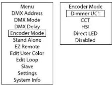
ENCODER MODE (Encoder Mode)
Four different modes are available as direct access (control element no. 9) for quick and easy adjustment of the spotlight without a remote controller.
Starting from the main display, press MENU to enter the main menu. Now use UP and DOWN to select the menu item Encoder Mode and confirm with ENTER. Then select the desired Encoder Mode using UP and DOWN and confirm with ENTER.
text_image
Menu DMX Address DMX Mode DMX Delay Encoder Mode Stand Alone EZ Remote Edit User Color Edit Loop Slave Settings System Info Encoder Mode Dimmer UC1 CCT HSI Direct LED DisabledRefer to the table below for encoder modes.
| Rotate encoder = change value, press encoder = confirm and next menu item | ||||||||
| Dimmer UC1 User Colour 1 Dimmer | ||||||||
| CCT Dimmer CCT = Colour Temperature Tint = tint | ||||||||
| HSI Dimmer Hue = colour shade Saturation = saturation | ||||||||
| Direct LED Dimmer Strobe Red Green Blue Amber Lime Cyan | ||||||||
| Disabled | Menu navigation | |||||||
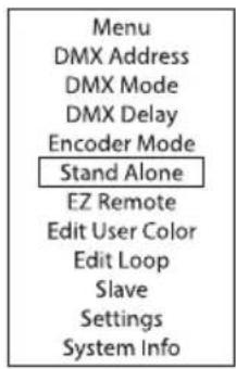
AUTO STANDALONE MODE
The 6 available auto programs partly comprise non-editable colour change sequences and partly random scenes. Brightness, running speed and delay (delay for slave units) can be set separately for each program.
Starting from the main display, press MENU to enter the main menu. Using UP and DOWN, select the menu item Stand Alone, confirm with ENTER, then select the submenu item Auto and confirm again with ENTER.

text_image
Menu DMX Address DMX Mode DMX Delay Encoder Mode Stand Alone EZ Remote Edit User Color Edit Loop Slave Settings System Info

This will take you to the submenu for setting the submenu items (see table, select with UP and DOWN, confirm with ENTER, change value with UP and DOWN, confirm with ENTER). The settings for each programme are made separately and are retained even after restarting the device.
| Program | Selects programs | Program 1 – 6 |
| Dimmer | Sets brightness | 0–100 |
| Speed | Sets running speed | 0–100 |
| Delay | Sets the delay for slave units | 0.0 – 2.0s |
STATIC STANDALONE MODE
The Static standalone mode allows the Dimmer, Strobe, R, G, B, A, L and C values to be set directly on the device with values in a similar way to with a DMX controller. In this way, an individual scene can be created without an additional DMX controller.
Starting from the main display, press MENU to enter the main menu. Using UP and DOWN, select the menu item Stand Alone and confirm with ENTER, then select Static and confirm once again with ENTER. Using UP and DOWN, now select the menu item that you wish to edit and confirm with ENTER. Use UP and DOWN to set the desired value. The strobe effect values correspond to those in channel 3 of the DMX table 16 CH 16 Bit Direct. Confirm all entries with ENTER.
text_image
Menu DMX Address DMX Mode DMX Delay Encoder Mode Stand Alone EZ Remote Edit User Color Edit Loop Slave Settings System Info
| Static | |
| Dimmer 000 - 100 | |
| Strobe 000 - 255 | |
| Red 000 - 100 | |
| Green 000 - 100 | |
| Blue 000 - 100 | |
| Amber 000 - 100 | |
| Lime 000 - 100 | |
| Cyan 000 - 100 |
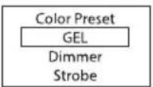
COLOUR PRESET STANDALONE MODE
49 different colour presets plus 8 individually adjustable user presets (Edit User Colour) are available. The brightness and a strobe effect can be set at a higher level.
Starting from the main display, press MENU to enter the main menu. Using UP and DOWN, select the menu item Stand Alone and confirm with ENTER, then select Colour Preset and confirm once again with ENTER. Now use UP and DOWN to select GEL and confirm with ENTER. The desired preset can now be selected with UP and DOWN; confirm the selection with ENTER. Use UP and DOWN to set the desired brightness (Dimmer) and the strobe (Strobe) and confirm with ENTER. The strobe effect values correspond to those in channel 3 of the DMX table 16 CH 16 Bit Direct. Confirm all entries with ENTER.

text_image
Menu DMX Address DMX Mode DMX Delay Encoder Mode Stand Alone EZ Remote Edit User Color Edit Loop Slave Settings System Info
| GEL Dark | Magenta |
| I | |
| Rose Pink | |
| User Colour 1 | |
| I | |
| User Colour 8 | |
| Dimmer 000-100 | |
| Strobe 000-255 | |
EDITING USER PRESETS (Edit User Colour)
The eight user presets available in the standalone mode Colour Preset can be edited individually. Starting from the main display, press MENU to enter the main menu. Use UP and DOWN to select Edit User Colour and confirm with ENTER. Now use UP and DOWN to select the desired preset and confirm with ENTER. You can now create an individual colour mix of red, green, blue, amber, lime and cyan with values ranging from 0 to 255 each (select colour with UP and DOWN, confirm with ENTER, change value with UP and DOWN, confirm with ENTER).

text_image
Menu DMX Address DMX Mode DMX Delay Encoder Mode Stand Alone EZ Remote Edit User Color Edit Loop Slave Settings System Info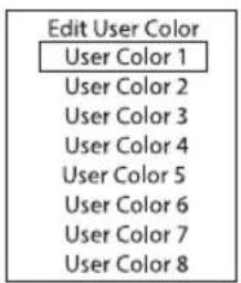
text_image
Edit User Color User Color 1 User Color 2 User Color 3 User Color 4 User Color 5 User Color 6 User Color 7 User Color 8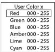
text_image
User Color x Red 000 - 255 Green 000 - 255 Blue 000 - 255 Amber 000 - 255 Lime 000 - 255 Cyan 000 - 255PLAYBACK LOOP STANDALONE MODE
Starting from the main display, press MENU to enter the main menu. Using UP and DOWN, select the menu item Stand Alone, confirm with ENTER, then select Playback Loop and confirm again with ENTER. Now use UP and DOWN to select one of the eight available loops (colour change programs) for playback and confirm with ENTER. All eight loops can be edited individually (Main menu -> Edit Loop).

text_image
Menu DMX Address DMX Mode DMX Delay Encoder Mode Stand Alone EZ Remote Edit User Color Edit Loop Slave Settings System Info

| Loop S | Selection of colour change programs | Loop 1 |
| I | ||
| Loop 8 | ||
| Loop Delay | Sets the delay for slave units | 0.0 – 2.0s |
EDIT LOOP (Edit LOOP)
Brightness, step duration and fade time can be set separately for all eight loops. Starting from the main display, press MENU to enter the main menu. Using UP and DOWN, select the menu item
Settings and confirm with ENTER. Using UP and DOWN, now select the desired loop for editing and confirm with ENTER.

text_image
Menu DMX Address DMX Mode DMX Delay Encoder Mode Stand Alone EZ Remote Edit User Color Edit Loop Slave Settings System Info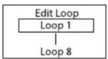

text_image
Loop x Dimmer0 - 100 t-Step 0 - 255 t-Fade 0 - 255 Step 1 | Step 8This will take you to the submenu for setting the submenu items (see table, select with UP and DOWN, confirm with ENTER, change value or status with UP and DOWN, confirm with ENTER). The settings for each loop are made separately and are retained even after restarting the device.
| EDIT LOOP (Loop 1 – Loop 8) | ||
| Dimmer Sets | brightness 0–100 | |
| Step time Sets | step time 0–255 | |
| Fade time Sets | s fade time 0–255 | |
| Step 1 49 colours from Colour Preset Dark Magenta – Rose Pink | ||
| Blackout Black | ||
| Step 2 “ “ | ||
| Step 3 49 colours from Colour Preset Dark Magenta – Rose Pink | ||
| Skip step Skip Step | ||
| Step 4 “ “ | ||
| Step 5 “ “ | ||
| Step 6 “ “ | ||
| Step 7 “ “ | ||
| Step 8 “ “ | ||
EZ REMOTE CONTROL VIA CAMEO UNICON (optionally available)
Starting from the main display, press MENU to enter the main menu. Now use UP and DOWN to select the menu item EZ Remote and confirm with ENTER. Now set the desired device ID (Fixture ID 1–8) using UP and DOWN and confirm with ENTER.
Connect the spotlight and UNICON using a DMX cable, select DMX Control in the UNICON menu, then EZ Remote, and enter the same unit ID. Now control the spotlight using RGB, GEL, CCT or HSI. By assigning different unit IDs, up to eight spotlights (or spotlight groups) can be controlled separately via UNICON. Alternatively, the control signals can be output to all eight IDs in parallel.

text_image
Menu DMX Address DMX Mode DMX Delay Encoder Mode Stand Alone EZ Remote Edit User Color Edit Loop Slave Settings System Info
SLAVE MODE
Standard slave mode: Starting from the main display, press MENU to enter the main menu. Now use UP and DOWN to select the menu item Slave, confirm with ENTER, select Slave Group 0 (Slave Group 0) and again confirm with ENTER. Connect the slave and the master units (same model, same software version) using a DMX cable, and enable one of the standalone modes on the master unit (Auto, Static, Colour Preset, Play Loop). The slave unit will now follow the master unit.

text_image
Menu DMX Address DMX Mode DMX Delay Encoder Mode Stand Alone EZ Remote Edit User Color Edit Loop Slave Settings System Info
Advanced slave mode: If you wish to control the slave units in master/slave mode using one of the Auto or Loop standalone modes, the control signal can be reproduced with a time delay of up to 24 steps. The delay is set in the submenu item Delay in the relevant standalone mode; the delay factor is set in the slave menu of the corresponding spotlight. This is a simple way to create a running light effect with a large number of spotlights that are all the same model and have the same software version. This is otherwise only possible using a suitable DMX controller and time-consuming programming.

text_image
Menu DMX Address DMX Mode DMX Delay Encoder Mode Stand Alone EZ Remote Edit User Color Edit Loop Slave Settings System Info Slave Group 0 - 24Assign the spotlights to one of up to 24 groups (plus Group 0) according to preference, whereby several spotlights can be assigned to one group. The group number is also the factor by which the delay time set in the master unit is multiplied.
Setup example:

flowchart
graph LR
    A["Master Unit Loop Delay 0.5s"] --> B["Slave Group 0"]
    B --> C["Slave Group 1"]
    C --> D["Slave Group 2"]
    D --> E["Slave Group 3"]
    E --> F["Slave Group 4"]
    F --> G["Slave Group 5"]
    E --> H["Slave Group 3"]
    H --> I["Slave Group 3"]
    I --> J["1,5s Delay"]
    J --> K["2s Delay"]
    K --> L["2,5s Delay"]
    style A fill:#f9f,stroke:#333
    style L fill:#f9f,stroke:#333
SYSTEM SETTINGS (Settings)
Starting from the main display, press MENU to enter the main menu. Using UP and DOWN, select the menu item Settings and confirm with ENTER.

text_image
Menu DMX Address DMX Mode DMX Delay Encoder Mode Stand Alone EZ Remote Edit User Color Edit Loop Slave Settings System InfoThis will take you to the submenu for setting the submenu items (see table, select with UP and DOWN, confirm with ENTER, change value or status with UP and DOWN, confirm with ENTER).
| Settings | |||||
| Disp Rev = Rotate | display OFF No display rotation | ||||
| ON Display is rotated by 180° (e.g. for overhead installation) | |||||
| Display Off Timer = Display lighting Off after 20s Deactivates after | approximately 20 seconds of inactivity | ||||
| Always On On permanently | |||||
| Signal Fail = Operational status with DMX signal fault | Hold last command is retained | ||||
| Blackout Activates blackout | |||||
| FTB 10s 10s fade to blackout | |||||
| User Colour 1 User Colour 1 is activated | |||||
| Dimmer Curve | = | Dimmer curve | Linear | Light intensity increases linearly with DMX value | |
| Exponential | Light intensity can be finely adjusted at lower DMX values and broadly adjusted at higher DMX values | ||||
| Logarithmic | Light intensity can be broadly adjusted at lower DMX values and finely adjusted at higher DMX values | ||||
| S-curve | Light intensity can be finely adjusted at lower and higher DMX values and broadly adjusted at medium DMX values | ||||
| Dim Response | = | Dimmer response | LED Lamp responds abruptly to changes in DMX value | ||
| Halogen | Light behaves like a halogen spotlight with slight brightness changes | ||||
| Red Shift = accurately | mimics the colour drift of dimming a halogen spotlight. When dimming the spotlight, the colour temperature changes automatically to increasingly warm white tones and amber (and vice versa). | None Colour drift is disabled | |||
| Dim to Warm Colour drift is enabled | |||||
| PWM = LED PWM | frequency 650Hz, | 1530Hz,3600Hz,12000Hz,18900Hz,25000Hz | Select LED PWM frequency | ||
| Colour Calibration = Colour calibration RAW R, G, B, | A, L and C with | maximum value 255 | |||
| Factory Cal Factory calibration of R, G,B, A, L and C (across all modes) | |||||
| Smart Cal Merging factory and RAW calibration | |||||
| User Cal Individual colour calibration. Cross-mode brightness setting of R, G,B, A, L and C with values from 0 – 255. | |||||
| Fan Mode = Fan control Off Deactivated fan with | greatly reduced brightness | ||||
| Constant High | Constant high fan speed | ||||
| Constant Medium | Constant average fan speed with reduced brightness, if necessary | ||||
| Constant Low | Constantly low fan speed with reduced brightness, if necessary | ||||
| Auto | Automatic fan speed control | ||||
| Load Default = Reset | settings Factory Reset to factory settings: | Perform reset with ENTER, cancel with MENU | |||
| Reset to Preset A: Perform reset with ENTER, cancel with MENU | |||||
| Reset to Preset B: Perform reset with ENTER, cancel with MENU | |||||
| Reset to Preset C: Perform reset with ENTER, cancel with MENU | |||||
| Store Default = Store | all system settings in 3 individual presets | Preset A Store | with ENTER | ||
| Preset B Store | with ENTER | ||||
| Preset C Store | with ENTER | ||||
Starting from the main display, press MENU to enter the main menu. Now use UP and DOWN to select the menu item System Info and confirm with ENTER.
text_image
Menu DMX Address DMX Mode DMX Delay Encoder Mode Stand Alone EZ Remote Edit User Color Edit Loop Slave Settings System InfoThis will take you to the submenu for accessing the system information (see table, selection with UP and DOWN, confirm with ENTER, change status with UP and DOWN, confirm with ENTER).
| System Info | ||||
| Firmware = Displays device firmware Main CPU | V1.xx | |||
| Temperature = Displays temperature of LED unit | Temperature LED xx°C / xx°F | |||
| Temperature unit °C (= display in degrees Celsius) | ||||
| Op Hours = Displays operating time Op Hours xx:xxh | Displays total operating time in hours and minutes | |||
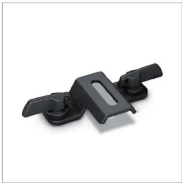
OPTIONAL ACCESSORIES
W-DMX™ receiver CLIDMXSTICKOmega holder
natural_image
Black plastic clip or bracket component with two protrusions and a central slot, isolated on white background (no text or symbols)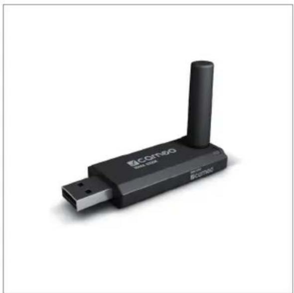
natural_image
Black COM80 Bluetooth device with USB port and antenna (no visible text or symbols on body)INSTALLING/REMOVING THE INTERCHANGEABLE LENS
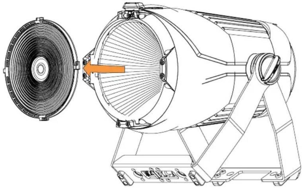
PLEASE NOTE:
- Do not operate the spotlight during the installation or removal of a lens.
- When installing or removing a lens, take care to avoid contaminating the reflector mirror and the LED unit.
- Do not operate the spotlight without the lens.
To replace and clean an interchangeable lens, first move the spring-loaded fuse holder on the top of the spotlight to the right to unlock it, and then flip it up (Figure A). Now turn the interchangeable lens clockwise out of the holder, applying slight pressure, and lift it off the front of the spotlight (Figure B).
A

natural_image
Technical diagram of a car wheel assembly with orange directional arrows indicating motion or force (no text or symbols)
natural_image
Technical line drawing of a mechanical assembly (no text or symbols)B
natural_image
Technical line drawing of a mechanical fan assembly with a circular fan on the left side (no text or symbols)To install an interchangeable lens, proceed in the opposite sequence, making sure that the spring-loaded fuse holder on the top of the spotlight engages again when it is folded down.
MOUNTING THE FILTER FRAME OR BARNDOOR
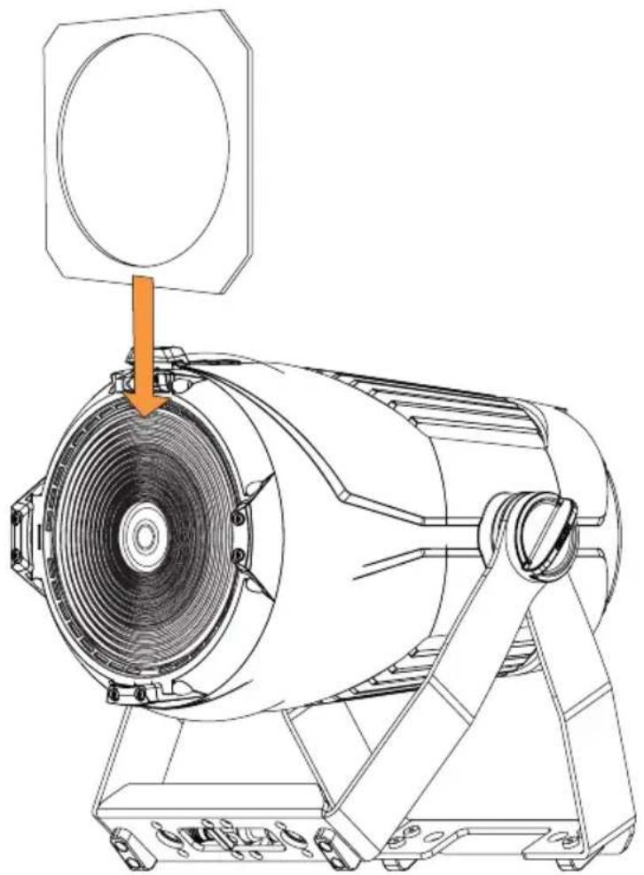
To mount the optionally available filter frame (or barndoor), first move the spring-loaded fuse holder on the top of the spotlight to the right to unlock it, and then flip it up (Figure A). Insert the filter frame (or barndoor) into the grooves of the lateral and bottom holders from above (Figure B).
A

natural_image
Technical diagram of a mechanical component with orange arrows indicating motion or force direction (no text or symbols)
natural_image
Technical line drawing of a mechanical assembly (no text or symbols)A

natural_image
Technical line drawing of a mechanical device with a circular component and orange arrow indicating direction (no text or symbols)Now fold the spring-loaded fuse holder on the top of the spotlight down again, making sure that it engages properly.
SETUP AND INSTALLATION

HAZARD: Overhead mounting requires extensive experience, including the calculation of the load limit values of the installation material and regular safety inspection of all installation materials and spotlights. If you do not have these qualifications, do not attempt to perform an installation yourself. Refer instead to a qualified professional. There is a risk of incorrectly mounted and secured devices coming loose and falling down. This can cause serious injury or death.
Thanks to its convenient double bracket, the lamp can be positioned in a suitable location on a level surface. Rubber feet prevent scratching of surfaces and ensure stability (A). An optional Omega bracket can be attached to the U-bracket for truss mounting (B). Alternatively, the integrated 16 mm TV spigot SPIN16 can be used for truss mounting (C). Installation on a truss is possible with a truss clamp. Suitable truss clamps are optionally available.
Loosen the two handle screws on the sides of the spotlight (D) to adjust the beam direction in the vertical plane and tighten the two handle screws again after adjustment.
Always take care to ensure firm connections and secure the spotlight by attaching a suitable safety cable to the securing lug on the back of the spotlight.

text_image
Technical diagram of a mechanical device with labeled components A, B, C, and DSPIN16 TV SPIGOT
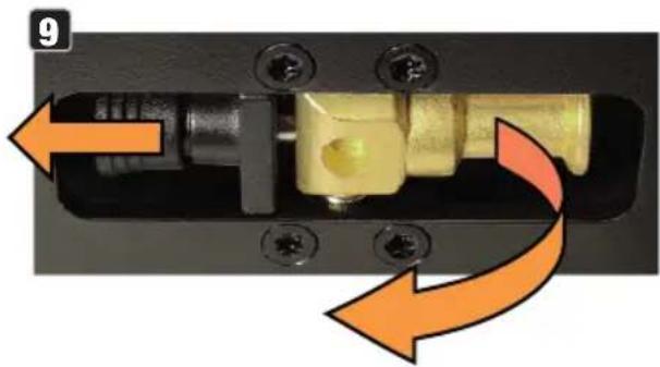
The spotlight features a 16 mm TV spigot that can be unfolded and retracted without tools. To unfold the TV spigot, pull the spring-loaded locking bolt out of the locking hole in the direction of the arrow (Figure A), fold the TV spigot forward and engage the locking bolt in the 90° offset locking hole (Figure B).
natural_image
Close-up of a mechanical component with orange arrows indicating motion or rotation, no visible text or symbols
natural_image
Close-up of a mechanical lock or latch component with a yellow handle and black housing, showing a yellow arrow pointing to a specific part (no text or symbols visible)CARE, MAINTENANCE AND REPAIR
In order to ensure the long-term, proper functioning of the device, it must be regularly cleaned and, if necessary, maintained. The maintenance requirement depends on the intensity of use and the environment in which it is used.
We generally recommend a visual inspection before each operation. Furthermore, we recommend carrying out all the applicable maintenance measures specified below once every 500 operating hours or, in the case of a lower intensity of use, at the latest after one year. Warranty claims may be limited in the event of defects resulting from inadequate maintenance.
CARE (carried out by user)

WARNING! Before carrying out any care or maintenance, the power supply – and, if possible, all device connections – must be disconnected.

PLEASE NOTE! Improper care can lead to impairment of the device or even its destruction.
- Housing surfaces must be cleaned with a clean, damp cloth. In doing so, ensure that no moisture can penetrate into the device.
- Air inlets and outlets must be regularly cleaned of dust and dirt. If compressed air is used, make sure that damage to the device is prevented (e.g. fans must be blocked in this case).
- Lines and plug contacts must be cleaned regularly and dust and dirt must be removed.
- In general, no cleaning agents or abrasive agents may be used, otherwise the surface finish may be damaged.
- Devices must generally be stored dry and protected from dust and dirt.
MAINTENANCE AND REPAIR (by qualified personnel only)
HAZARD! There are live components in the device. Even after disconnecting the mains connection, there may still be residual voltage in the device, for example, due to charged capacitors.

PLEASE NOTE! There are no user-serviceable assemblies in the device.

PLEASE NOTE! Maintenance and repair work may only be carried out by qualified specialist personnel authorised by the manufacturer. If in doubt, consult the manufacturer.

PLEASE NOTE! Improperly performed maintenance work may affect the warranty claim.
DIMENSIONS

text_image
DIMENSIONS 253.5 466.3 368.0 216.5 301.4
natural_image
Technical line drawing of a mechanical component with dimension标注 (no text or symbols on the diagram itself)TECHNICAL DATA
| Item number CLLUXISFC | |
| Product category Static LED light | |
| Type PAR light | |
| Light source 200 W 6in1 RGBALC COB LED | |
| Luminous flux 8536 lm | |
| Lense / optic COB Reflector with 160 mm quick change lense for different beam angles | |
| PWM frequency 650 Hz; 1530 Hz; 3600 Hz; 12 kHz; 18.9 kHz; 25 kHz | |
| CRI > 94 | |
| Beam angle / field angle 9°/16°; 21°/29°; 51°/63° (interchangeable lenses with fixed angle) | |
| Color mixing RGBALC | |
| Color control modes RGB; Direct (RGBALC); CCT; HSI; Color Presets | |
| Control options DMX; RDM; Wireless-DMX - Ready (iDMX-Stick optionally available); Stand-Alone; Master-Slave; EZ Remote | |
| Physical data connectors XLR 3-Pin In/Out; XLR 5-Pin In/Out; iDMX-Stick-Slot | |
| DMX modes | 1CH User Color; 3CH Presets+D; 3CH RGB; 5CH RGB+D; 6CH 8bit; 9CH Direct+Control; 9CH Direct+D; 7CH RGB-CCT; 12CH Direct-CCT; 10CH HSI-CCT; 12CH 16bit; 16CH Direct 16bit; 20CH Full Access |
| DMX functions | Dimmer; Strobe; R; G; B; A; L; C; Hue; Sat; CCT; Tint; Color-Presets; Settings; EZ-Chase |
| RDM functions | Cameo Standard |
| Stand alone | Encoder-Mode: Dimmer UC1; CCT; HSI; Direct LED / Auto; Static; Preset; Loop |
| System settings | Wireless; Display; Signal Fail; Dimmer; Dim-Response; Red-Shift; PWM; Calibration; Fan Mode; Default |
| User interface | 4-button; turn-push-encoder |
| Display | 2-row OLED |
| IP rating | IP 20 indoor use |
| Ambient temperature rating | -10°C - 40°C |
| Humidity | < 80% non condensing |
| Cooling | Fan Off, Constant High, Constant Medium, Constant Low, Auto |
| Operation voltage | 100V AC - 240V AC; 50Hz-60Hz |
| Max. current | 1,2 A @230 V; 2,35 A @110 V |
| Inrush current 12.1 A | |
| Max. power consumption | 280 W |
| Fuse T4A | |
Cos Phi 0.886
Minimum distance to the 0,5 m illuminated surface
Minimum distance to normal 0,5 m flammable materials
Power connectors True1 compatible
Power link 7 Units @ 230 V ; 3 Units @ 110 V
Housing Magnesium and aluminium die cast, black powder coated
Dimensions h/w/d 466 mm x 302 mm x 216 mm (hanging); 430 mm x 281 mm x 302 mm (floor mount upright)
Weight 7.0 kg
MINIMUM DISTANCE TO ILLUMINATED SURFACE

This symbol with distance specification in metres (m) indicates the minimum distance between the light head and the illuminated surface. In this example, the distance is 0.5 m.
MINIMUM DISTANCE TO NORMALLY FLAMMABLE MATERIALS
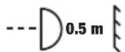
This symbol with distance specification in metres (m) indicates the minimum distance between the light head and normally flammable materials. In this example, the distance is 0.5 m.
DISPOSAL

Packaging:
- Packaging can be fed into the reusable material cycle using the usual disposal methods.
- Please separate the packaging in accordance with the disposal laws and recycling regulations in your country.
Device:
- This device is subject to the European Directive on Waste Electrical and Electronic Equipment, as amended. WEEE Directive Waste Electrical and Electronic Equipment. Old appliances do not belong in household waste. The old device must be disposed of via an approved disposal company or a municipal disposal facility. Please observe the applicable regulations in your country!
- Observe all disposal laws applicable in your country.
- As a private customer, you can obtain information on environmentally-friendly disposal options from the seller of the product or the appropriate regional authorities.
MANUFACTURER'S DECLARATIONS
MANUFACTURER'S WARRANTY & LIMITATION OF LIABILITY
Adam Hall GmbH, Adam-Hall-Str. 1, D-61267 Neu Anspach / E-mail Info@adamhall.com / +49 (0)6081 / 9419-0.
Our current warranty conditions and limitation of liability can be found at:
https://cdn-shop.adamhall.com/media/pdf/Manufacturers-Declarations-CAMEO_DE_EN_ES_FR.pdf.
Contact your sales partner for service.
FCC STATEMENT
This device complies with Part 15 of the FCC Rules. Operation is subject to the following two conditions:
(1) This device may not cause harmful interference, and
(2) This device must accept any interference received, including interference that may cause undesired opera
UKCA- CONFORMITY
Hereby, Adam Hall Ltd. declares that this product meets the following guidelines (where applicable)
Electrical Equipment (Safety) Regulations 2016
Electromagnetic Compatibility Regulations 2016 (SI 2016/1091)
The Restriction of the Use of Certain Hazardous Substances in Electrical and Electronic Equipment Regulation 2012 (SI 2012/3032)
Radio Equipment Regulations 2017(SI 2016/2015)
UKCA- DECLARATION OF CONFORMITY
Products that are subject to Electrical Equipment(Safety)Regulation 2016, EMC Regulation 2016 or RoHS Regulation can be requested at info@adamhall.com.
Products that are subject to the Radio Equipments Regulations 2017 (SI2017/1206) can be downloaded from www.adamhall.com/compliance/
SUBJECT TO MISPRINTS AND ERRORS, AS WELL AS TECHNICAL OR OTHER MODIFICATIONS!
DEUTSCH
text_image
10 SAFETY cameo® 7 8 MENU ENTER UP DOWN No User-replacable Parts Inside! LUXIS® FC DMX IN DMX IN DMX OUT DMX OUT IDMX STICK 6 CAUTION MAX OUT CURRENT: 12 A FAE OF ELECTRIC DEVICE 35.00 GB FUSE T4 A 250 V POWER IN POWER OUT MAX OUT CURRENT: 12 A WEIGHT: 7.0 kg CE UK CA POWER CONSUMPTION: 280 W 100 - 240 V AC 50/60 Hz Camero® is a registered brand of the Adam Hall Group Adam Hall Small Adam-Hall-Strt 61267 New-Ansprach Germany I Designs and engineered in Germany, assembled in PZLG I www.adamhall.com. Adam Hall Ltd. The Seebild Business Centre SS3 SQY Elexi I United Kingdom1 POWER IN
text_image
Edit User Color User Color 1 User Color 2 User Color 3 User Color 4 User Color 5 User Color 6 User Color 7 User Color 8
text_image
User Color x Red 000 - 255 Green 000 - 255 Blue 000 - 255 Amber 000 - 255 Lime 000 - 255 Cyan 000 - 255flowchart
graph LR
    A["Master Unit\nLoop Delay 0.5s"] --> B["Slave Group 0"]
    B --> C["Slave Group 1"]
    C --> D["Slave Group 2"]
    D --> E["Slave Group 3"]
    E --> F["Slave Group 3"]
    F --> G["Slave Group 3"]
    G --> H["Slave Group 4"]
    H --> I["Slave Group 5"]
    E --> J["Slave Group 4"]
    J --> K["2.5s Delay"]
    style A fill:#ccc,stroke:#333
    style K fill:#ccc,stroke:#333
natural_image
Black plastic clip or bracket component with no visible text or symbols
natural_image
Black COMTEQ USB device with a vertical port, shown against a white background (no text or symbols visible on the device body)WECHSELLINSE MONTIEREN BZW. DEMONTIEREN
HINWEISE:
natural_image
Technical diagram of a car wheel assembly with orange arrows indicating motion or force direction (no text or symbols)
natural_image
Technical line drawing of a mechanical assembly (no text or symbols visible)B

natural_image
Technical line drawing of a mechanical device with a fan-like component and internal blades (no text or symbols)natural_image
Technical diagram of a car wheel assembly with orange directional arrows indicating motion or force (no text or symbols)
natural_image
Technical line drawing of a mechanical assembly (no text or symbols)A

natural_image
Technical line drawing of a mechanical device with a circular component and orange arrow indicating direction (no text or symbols)text_image
Technical diagram of a mechanical device with labeled components A, B, C, and DSPIN16 TV-ZAPFEN
natural_image
Close-up of a mechanical component with orange arrows indicating motion or rotation, no visible text or symbols
natural_image
Close-up of a mechanical component with a yellow cylindrical shaft and black housing, featuring a black bolt and screw holes (no text or symbols visible)natural_image
Technical line drawing of a mechanical component with dimension标注 (no text or symbols on the diagram itself)TECHNISCHE DATEN
https://cdn-shop.adamhall.com/media/pdf/Manufacturers-Declarations-CAMEO_DE_EN_ES_FR.pdf.
text_image
10 SAFETY camoo® 7 8 MENU ENTER UP DOWN No User-replacable Parts Indel LUXIS® FC DMX IN DMX IN DMX OUT DMX OUT IDMX STICK 6 CAUTION MAX OUT CURRENT: 12 A FAE OF ELECTRIC ENER T4 A 250 V POWER IN POWER OUT CE UK CA POWER CONSUMPTION: 280 W 100 - 240 V AC 50/60 Hz Camoo® is a registered brand of the Adam Hall Group Adam Hall Small Adam-Hall-SitC1 61/67 New-Anschach Germany I Designs and engineered in Germany, assembled in PZLG I www.adamhall.com. Adam Hall Ltd. The Seobled Business Centre S33 SQY Essex I United Kingdom1 POWER IN (ENTRÉE D'ALIMENTATION)
text_image
Edit User Color User Color 1 User Color 2 User Color 3 User Color 4 User Color 5 User Color 6 User Color 7 User Color 8
text_image
User Color x Red 000 - 255 Green 000 - 255 Blue 000 - 255 Amber 000 - 255 Lime 000 - 255 Cyan 000 - 255MODE DE FONCTIONNEMENT STAND ALONE PLAYBACK LOOP
natural_image
Black plastic clip or bracket component with two protrusions and a central slot, isolated on white background (no text or symbols)
natural_image
Black COM80 Bluetooth device with USB port and antenna (no visible text or symbols on body)MONTAGE OU DÉMONTAGE DE LA LENTILLE DE RECHANGE
REMARQUES :
natural_image
Technical diagram of a car wheel assembly with orange directional arrows indicating motion or force (no text or symbols)
natural_image
Technical line drawing of a mechanical assembly (no text or symbols)B

natural_image
Technical line drawing of a mechanical device with a fan-like component and a highlighted orange section (no text or symbols)natural_image
Technical diagram of a mechanical component with orange arrows indicating motion or force direction (no text or symbols)
natural_image
Technical line drawing of a mechanical assembly (no text or symbols)A

natural_image
Technical line drawing of a mechanical device with a circular component and orange arrow indicating direction (no text or symbols)text_image
Technical diagram of a mechanical device with labeled components A, B, C, and DPIVOT TV SPIN16
natural_image
Close-up of a mechanical component with orange arrows indicating motion or rotation, no visible text or symbols
natural_image
Close-up of a mechanical lock or latch component with a yellow handle and black housing, showing a yellow arrow pointing to the lock (no text or symbols visible)ENTRETIEN, MAINTENANCE ET RÉPARATION
natural_image
Technical line drawing of a mechanical component with dimension标注 (no text or symbols on the diagram itself)CARACTÉRISTIQUES TECHNIQUES
Directive CEM (2014/30/UE)
RoHS (2011/65/UE)
RED (2014/53/UE)
DÉCLARATION DE CONFORMITÉ CE
text_image
Edit User Color User Color 1 User Color 2 User Color 3 User Color 4 User Color 5 User Color 6 User Color 7 User Color 8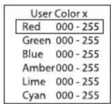
text_image
User Color x Red 000 - 255 Green 000 - 255 Blue 000 - 255 Amber 000 - 255 Lime 000 - 255 Cyan 000 - 255natural_image
Black plastic clip or bracket component with two protrusions and a central slot, isolated on white background (no text or symbols)
natural_image
Black COM80 Bluetooth device with USB port and antenna (no visible text or symbols on body)MONTAJE O DESMONTAJE DE LA LENTE INTERCAMBIABLE INDICACIONES:
natural_image
Technical diagram of a car wheel assembly with orange directional arrows indicating motion or force (no text or symbols)
natural_image
Technical line drawing of a mechanical assembly (no text or symbols)B

natural_image
Technical line drawing of a mechanical device with a fan-like component and a highlighted orange section (no text or symbols)natural_image
Technical diagram of a car wheel assembly with orange arrows indicating motion or force direction (no text or symbols)
natural_image
Technical line drawing of a mechanical assembly with internal components (no text or symbols)A

natural_image
Technical line drawing of a mechanical device with a circular component and orange arrow indicating direction (no text or symbols)text_image
Technical diagram of a mechanical device with labeled components A, B, C, and Dnatural_image
Close-up of a mechanical component with orange arrows indicating motion or force direction (no text or symbols)
natural_image
Close-up of a mechanical component with a golden cylindrical pin inserted into a black housing, showing a yellow arrow pointing to the part (no text or symbols visible)natural_image
Technical line drawing of a mechanical component with dimension标注 (no text or symbols on the diagram itself)DATOS TÉCNICOS
https://cdn-shop.adamhall.com/media/pdf/Manufacturers-Declarations-CAMEO DE EN ES FR.pdf.
text_image
10 SAFETY fcamoo® 7 8 MENU ENTER UP DOWN No User-replacable Parts Indel LUXIS® FC DMX IN DMX IN DMX OUT DMX OUT IDMX STICK 6 CAUTION FUSE T4 A 250 V POWER IN POWER OUT MAX OUT CURRENT: 12 A WEIGHT: 7.0 kg CE UK CA POWER CONSUMPTION: 280 W 100 - 240 V AC 50/60 Hz Cameo® is a registered brand of the Adam Hall Group Adam Hall GmbH, Adam-Hall-Stc.T 61267 Neu-Aspach Germany I(Designes and engineered in Germany, assembled in P2.C.I www.adamhall.com Adam Hall Ltd. The Seedbed Business Centre SSB 90Y Essex I United Kingdom1 POWER IN
text_image
Edit User Color User Color 1 User Color 2 User Color 3 User Color 4 User Color 5 User Color 6 User Color 7 User Color 8
text_image
User Color x Red 000 - 255 Green 000 - 255 Blue 000 - 255 Amber000 - 255 Lime 000 - 255 Cyan 000 - 255TRYB PRACY STANDALONE PLAYBACK LOOP
flowchart
graph LR
    A["Master Unit Loop Delay 0.5s"] --> B["Slave Group 0"]
    B --> C["Slave Group 1"]
    C --> D["Slave Group 2"]
    D --> E["Slave Group 3"]
    E --> F["Slave Group 4"]
    F --> G["Slave Group 5"]
    E --> H["Slave Group 3"]
    H --> I["Slave Group 3"]
    I --> J["1,5s Delay"]
    J --> K["2s Delay"]
    K --> L["2,5s Delay"]
    style A fill:#f9f,stroke:#333
    style L fill:#f9f,stroke:#333
USTAWIENIA SYSTEMU (Settings)
natural_image
Black plastic clip or bracket component with two protrusions, isolated on white background (no text or symbols)
natural_image
Black CRT800 wireless router with USB port and antenna (no visible text or symbols on body)MONTAŻ I DEMONTAŻ WYMIENNEJ SOCZEWKI
WSKAZÓWKI:
natural_image
Technical diagram of a car wheel assembly with orange directional arrows indicating motion or force (no text or symbols)
natural_image
Technical line drawing of a mechanical assembly with internal components (no text or symbols)B

natural_image
Technical line drawing of a mechanical device with a fan-like component and a highlighted orange section (no text or symbols)natural_image
Technical diagram of a car wheel assembly with orange arrows indicating motion or force direction (no text or symbols)
natural_image
Technical line drawing of a mechanical assembly (no text or symbols)A

natural_image
Technical line drawing of a mechanical device with a circular component and orange arrow indicating direction (no text or symbols)text_image
Technical diagram of a mechanical device with labeled components A, B, C, and DADAPTER TV SPIN16
natural_image
Close-up of a mechanical component with orange arrows indicating motion or force direction (no text or symbols)
natural_image
Close-up of a mechanical lock or latch component with a yellow cylindrical pin inserted, showing bolt holes and a black housing (no text or symbols visible)CZYSZCZENIE, KONSERWACJA I NAPRAWY
natural_image
Technical line drawing of a mechanical component with dimension标注 (no text or symbols on the diagram itself)DANE TECHNICZNE
text_image
10 SAFETY cameo® 7 8 MENU ENTER UP DOWN No User-replacable Parts Inside! LUXIS® FC DMX IN DMX IN DMX OUT DMX OUT IDMX STICK 6 CAUTION FAE OF THE WORK TO NOT ON FUSE T4 A 250 V POWER IN POWER OUT MAX OUT CURRENT: 12 A WEIGHT: 7.0 kg CE UK CA POWER CONSUMPTION: 280 W 100 - 240 V AC 50/60 Hz Cameo® is a registered brand at the Adam Hall Group Adam Hall GmbH. Adam-Kit-Sitz 67267 Neu-Arjusch Germany. I designed and engineered in Germany, assembled in PRCI www.adamhall.com. Adam Hall Ltd. The Seedbred Business Centre 333 SQY Essex United Kingdom1 POWER IN
text_image
Edit User Color User Color 1 User Color 2 User Color 3 User Color 4 User Color 5 User Color 6 User Color 7 User Color 8
text_image
User Color x Red 000 - 255 Green 000 - 255 Blue 000 - 255 Amber 000 - 255 Lime 000 - 255 Cyan 000 - 255MODALITÀ DI FUNZIONAMENTO STAND-ALONE PLAYBACK LOOP
natural_image
Black plastic clip or bracket component with two protrusions and a central slot (no text or symbols visible)
natural_image
Black CRT800 wireless router with USB port and antenna (no visible text or symbols on body)MONTAGGIO /SMONTAGGIO DELLA LENTE INTERCAMBIABILE
ATTENZIONE:
natural_image
Technical diagram of a car wheel assembly with orange directional arrows indicating motion or force (no text or symbols)
natural_image
Technical line drawing of a mechanical assembly (no text or symbols)B

natural_image
Technical line drawing of a mechanical device with a fan blade and central hub, showing internal components without any text or symbols.natural_image
Technical diagram of a mechanical component with orange arrows indicating motion or force direction (no text or symbols present)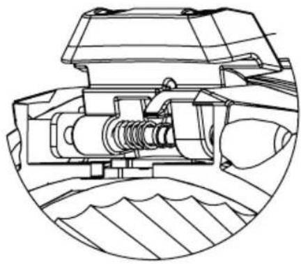
natural_image
Technical line drawing of a mechanical assembly (no text or symbols)A
natural_image
Technical line drawing of a mechanical device with a circular component and orange arrow indicating direction (no text or symbols)text_image
Technical diagram of a mechanical device with labeled components A, B, C, and DCODOLO TV SPIN16
natural_image
Close-up of a mechanical component with orange arrows indicating motion or rotation, no visible text or symbols
natural_image
Close-up of a mechanical lock or latch component with a yellow cylindrical shaft and black housing, showing a bolted joint and an orange arrow pointing to a specific part (no text or symbols visible)natural_image
Technical line drawing of a mechanical component with dimension标注 (no text or symbols on the diagram itself)DATI TECNICI
https://cdn-shop.adamhall.com/media/pdf/Manufacturers-Declarations-CAMEO_DE_EN_ES_FR.pdf.
EN: (1*) After the adjustments have been made, set the value to 000 to avoid disturbance by endless function call.