8513HIM - Intercom COMELIT - Free user manual and instructions
Find the device manual for free 8513HIM COMELIT in PDF.

| Product type | Audio/video intercom |
| Brand | COMELIT |
| Model | 8513HIM |
| Power supply (indoor unit) | Art. 1441B (12V DC) |
| Power supply (outdoor unit) | Art. 1595 (12V DC) |
| Power consumption | Less than 10 W |
| Dimensions (indoor unit) | 140 x 80 x 30 mm |
| Dimensions (outdoor unit) | 160 x 80 x 40 mm |
| Weight (indoor unit) | 200 g |
| Weight (outdoor unit) | 300 g |
| Main functions | Two-way communication, door opening, video vision, call, intercom |
| Network connection | Ethernet RJ45 (CAT5 cable or higher), ViP system |
| Maintenance and cleaning | Clean with a dry cloth, do not use liquids |
| Safety | Installation by a qualified electrician, compliance with electrical standards |
| Kit contents | Indoor unit Art.6202WK, bracket Art.6231, power supply Art.1441B, landing derivation Art.1440, apartment gateway Art.1456 or 1456S, outdoor unit Ikall Art.4894I/IM, power supply Art.1595 |
| App compatibility | Intercall Vip app (Android and iOS) |
| Warranty | Compliant with directive 2006/95/EC |
Frequently Asked Questions - 8513HIM COMELIT
User questions about 8513HIM COMELIT
0 question about this device. Answer the ones you know or ask your own.
Ask a new question about this device
Download the instructions for your Intercom in PDF format for free! Find your manual 8513HIM - COMELIT and take your electronic device back in hand. On this page are published all the documents necessary for the use of your device. 8513HIM by COMELIT.
USER MANUAL 8513HIM COMELIT
natural_image
Green stylized icon of a suitcase with a handle, no text or symbols presentManuale Tecnico KIT VIP Art. 8511I, 8511IM, 8512IM, 8513IM
Technical Manual for VIP KIT Art. 8511I, 8511IM, 8512IM, 8513IM
Manuel technique KIT VIP Art. 8511I, 8511IM, 8512IM, 8513IM
Technische handleiding KIT VIP Art. 8511I, 8511IM, 8512IM, 8513IM
Technisches Handbuch SET VIP Art. 8511I, 8511IM, 8512IM, 8513IM
Manual técnico KIT VIP arts. 8511I, 8511IM, 8512IM y 8513IM
Manual técnico KIT VIP art. 8511I, 8511IM, 8512IM, 8513IM
Passion.Technology.Design.
Avvertenze
natural_image
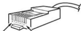
Green and black wire crimping tool (no text or symbols visible)natural_image
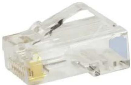
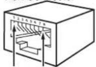
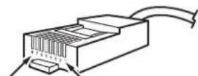
Close-up of a transparent plastic electrical connector with a yellow internal component (no text or symbols visible)RJ45 PINS
Pin 1 Pin 8 Pin 8 Pin 1
natural_image
Close-up of a white plastic object being measured by a ruler, showing measurement markings (no text or symbols visible)
natural_image
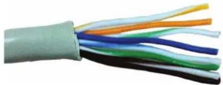
Close-up of a multi-core electrical cable with visible color bands (no text or symbols)- Aprite a ventaglio i fili e tagliate i cavi "Blu", "Bianco / Blu", "Bianco / Marrone", "Marrone".

natural_image
Close-up of a multi-colored cable with visible color bands, no text or symbols present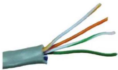
natural_image
Close-up of a multi-colored electrical cable with visible wires (no text or symbols)natural_image
Close-up of a hand holding a small electronic component with a multicolored chip (no visible text or symbols)natural_image
Close-up of a transparent electrical connector with internal wiring and a close-up view showing a cable (no text or symbols visible)natural_image
Close-up of hands using a wire to apply plastic components on a mechanical component (no visible text or symbols)natural_image
Close-up of a transparent electrical connector with visible internal wiring and color-coded wires (no text or symbols)Warning
• Install the equipment by carefully following the instructions given by the manufacturer and in compliance with the standards in force.
- All the equipment must only be used for the purpose it was designed for. Comelit Group S.p.A. declines any responsibility for improper use of the apparatus, for any alterations made by others for any reason or for the use of non-original accessories or materials.
• All the products comply with the requirements of Directive 2006/95/EC (which replaced Directive 73/23/EEC and subsequent amendments), as certified by the CE mark they carry.
- Do not insert objects or pour liquids into the device.
• Installation, mounting and assistance procedures for electrical devices must only be performed by specialised electricians.
- Cut off the power supply before carrying out any maintenance work.
This document may not be reproduced, even in part, without the express written consent of Comelit Group spa. The brands and commercial names appearing in this publication remain the property of their respective owners.

For complete ViP system installation and wiring information, please refer to the relevant technical manual, which is also available from the website www.comelitgroup.com.
| KIT CONTENTS 8511I 8511IM 8512IM 8513IM | ||||
| 1 Internal unit Art. 6202WK Art. 6202WK Art. 6202WK | ||||
| Backplate Art. 6231 Art. 6231 Art. 6231 | ||||
| 1 Power supply unit for internal unit | Art. 1441B | Art. 1441B | Art. 1441B | Art. 1441B |
| Floor distributor | Art.1440 | Art. 1440 | ||
| Apartment Gateway * | Art. 1456SGATEWAY SLAVE | Art. 1456GATEWAY MASTER | ||
| 1 Ikall external unit | Art. 4894I(Ikall) | Art. 4894IM**(Ikall metal) | Art. 4894IM**(Ikall metal) | Art. 4894IM**(Ikall metal) |
| 1 Power supply unit for external unit | Art. 1595 | Art. 1595 | Art. 1595 | Art. 1595 |
| The "Intercall Vip" application is available to download from Google play (for Android devices) and the Apple Store (for IOS devices). | ||||

DEFAULT: the ViP address of internal unit Art. 6202WK is set to 00000001 "Master", the ViP address for external unit Art. 4894I / Art. 4894IM is set to 00000100.
The IP address of gateway Art. 1456 and Art. 1456S is set to 192.168.1.200.
* For apartment gateway wiring configuration, please refer to the Technical Manual for Art. 1456 and Art. 1456S.
** An additional pre-programmed lkall metal external unit Art. 4895IM (and corresponding power supply unit for external unit Art. 1595) is available to purchase separately.
Guide to fitting a network cable for connecting the PC to Comelit switch Art. 1440 or between PC and POE output
The recommended cables are:
- UTP (Unshielded Twisted Pair): not protected from electromagnetic interference, maximum length 100 metres. We recommend the use of a Panduit cable code NUL5C04BU-CE.
- STP (Shielded Twisted Pair): similar to the UTP but with a metal sheath.
The UTP and STP can fall into various categories. Category 5 (CAT 5) cables or greater must be used for the ViP system.
The tools required for fitting are as follows:
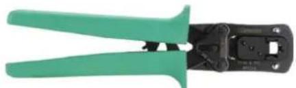
- 6-P 8-P crimping pliers.
We recommend using 8-pole Panduit pliers code MPT5-8A.
natural_image
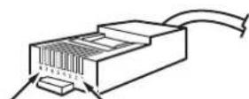
Green and black wire crimping tool (no text or symbols visible)- 2 RJ45 connectors for each section of cable.
We recommend using Panduit connectors code MP588-L.
natural_image
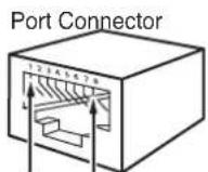
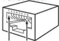
Close-up of a transparent plastic electrical connector with a yellow internal component (no text or symbols visible)RJ45 PINS
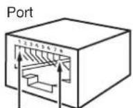
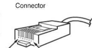
Port Connector

Pin 1 Pin 8 Pin 8 Pin 1
Fitting procedure
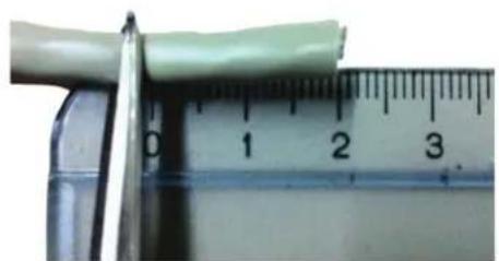
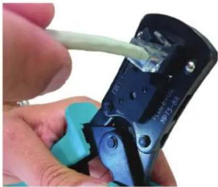
- Most crimping pliers have two pairs of blades, one pair on one side to strip the wires and another pair on the other side to cut the wires. If the pliers do not allow you to cut the cable sheath, you should use a blade and cut the sheath with it, removing a length of about two centimetres. Be especially careful not to cut or scratch the wires inside the sheath; once cut, most sheaths break if they are folded or pulled.
natural_image
Close-up of a white plastic object being cut by a ruler, showing measurement markings (no text or symbols visible)
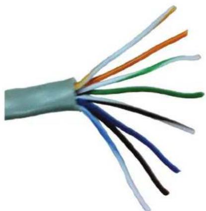
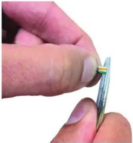
- When you have removed the sheath, you will have four pairs of wires, twisted together two by two and of different colours. Untwist the wire pairs so you have 8 separate wires, but make sure you mark them if they are not of different colours (in some cables, the white/colour wires are completely white).
natural_image
Close-up of a multi-core electrical cable with visible color bands (no text or symbols)- Fan out the wires and cut the "Blue", "White/Blue", "White/Brown" and "Brown" ones.
natural_image
Close-up of a multi-colored cable with visible color bands, no text or symbols present
natural_image
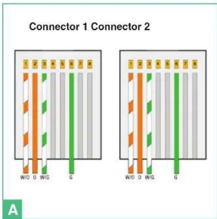
Close-up of a multi-colored electrical cable with visible wires (no text or symbols)- Arrange the wires in the order in which you need to crimp them from left to right. The cable configuration is illustrated in Table 1 and Figure A.
| Table 1 | |
| Connector 1 Connector 2 | |
| White / Orange White / Orange | |
| Orange Orange | |
| White / Green White / Green | |
| Empty Empty | |
| Empty Empty | |
| Green Green | |
| Empty Empty | |
| Empty Empty | |
| N.B.: if the cable colours are different, simply maintain the correct correspondences. | |
text_image
Connector 1 Connector 2 1 2 3 4 5 6 7 8 W/O O W/G G 1 2 3 4 5 6 7 8 W/O O W/G G A- Hold the wires tightly between two fingers and flatten them so that they are side by side, then straighten them by pulling them taut with your fingers to remove slight curves caused by the previous twisting. Make sure they stay in the correct order.
- Continuing to hold them taut, trim the excess by 2 centimetres, so that they are all the same length.
natural_image
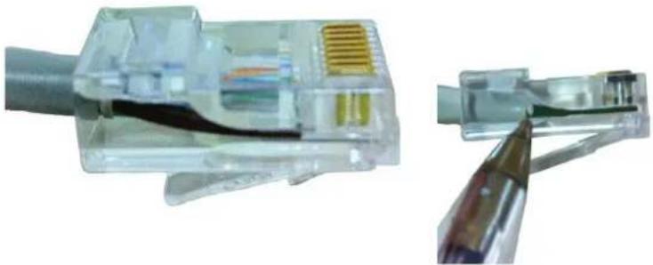
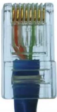
Close-up of a hand holding a small electronic component, possibly a multimeter or sensor, with no visible text or symbols.- Insert the wires into the RJ45 connector, still holding them tightly between your fingers. The connector tab should be facing downwards and not visible. The insulating sheath should just reach the edge of the connector.
natural_image
Close-up of a transparent electrical connector with internal wiring and a close-up view showing a cable (no text or symbols visible)- Make sure the wires are fully inserted by inspecting the side of the transparent connector. Next, insert the connector into the crimping pliers and, using both hands, crimp the connector so as to secure the wires. The pliers should not open if they did not close fully.
natural_image
Close-up of hands using a wire to apply a plastic cable to a mechanical component (no visible text or symbols)- Now repeat steps 1 to 8 above, to crimp the cable on the other side.
Complete connector example
natural_image
Close-up of a transparent electrical connector with visible internal wiring and color-coded wires (no text or symbols)Avertissement
natural_image
Green and black wire crimping tool (no text or symbols visible)natural_image
Close-up of a transparent plastic electrical connector with a gold socket (no visible text or symbols)RJ45 PINS


Pin 1 Pin 8 Pin 8 Pin 1
natural_image
Close-up of a white plastic strip being cut with a ruler, showing measurement markings (no text or symbols on the object itself)
natural_image
Close-up of a multi-core electrical cable with visible color bands (no text or symbols)natural_image
Close-up of a multi-colored cable with visible color bands, no text or symbols present
natural_image
Close-up of a multi-colored electrical cable with visible wires (no text or symbols)text_image
1 2 3 4 5 6 7 8 W/O O W/G G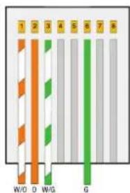
text_image
1 2 3 4 5 6 7 8 W/D D W/G GA
natural_image
Close-up of a hand holding a small electronic component, possibly a flexible capacitor or sensor, with no visible text or symbols.natural_image
Close-up of a transparent electrical connector with internal wiring and connectors (no text or symbols visible)natural_image
Close-up of hands using a wire to apply plastic components on a mechanical component (no visible text or symbols)natural_image
Close-up of a transparent electrical connector with visible internal wires and color bands (no text or symbols)Waarschuwingen
natural_image
Green and black wire crimping tool (no text or symbols visible)natural_image
Close-up of a transparent plastic electrical connector with a yellow internal component (no visible text or symbols)RJ45 PINS
Port Connector


Pin 1 Pin 8 Pin 8 Pin 1
Montageprocedure.
natural_image
Close-up of a white plastic object being cut by a ruler, showing measurement markings (no text or symbols visible)
natural_image
Close-up of a multi-core electrical cable with visible color bands (no text or symbols)- Open de draden in waaiervorm en snijd de "Blauwe", "Wit / Blauwe", "Wit / Bruine", "Bruine" draden door.

natural_image
Close-up of a multi-colored electrical cable with visible color bands (no text or symbols)
natural_image
Close-up of a multi-colored electrical cable with visible wires (no text or symbols)text_image
Connector 1 Connector 2 1 2 3 4 5 6 7 8 W/O O W/G G 1 2 3 4 5 6 7 8 W/O O W/G G Anatural_image
Close-up of a hand holding a small electronic component with a multicolored cable (no visible text or symbols)natural_image
Close-up of a transparent electrical connector with internal wiring and connectors (no text or symbols visible)natural_image
Close-up of hands using a crimping tool to apply plastic cable to a black mechanical component (no visible text or symbols)natural_image
Close-up of a transparent electrical connector with visible internal wires and color bands (no text or symbols)Wichtige Hinweise
natural_image
Green and black wire crimping tool (no text or symbols visible)natural_image
Close-up of a transparent plastic electrical connector with a yellow internal component (no visible text or symbols)RJ45 PINS
Pin 1 Pin 8
text_image
ConnectorPin 8
Pin 1
Einbauprozedur.
natural_image
Close-up of a white plastic strip being cut with a ruler, showing measurement markings (no text or symbols)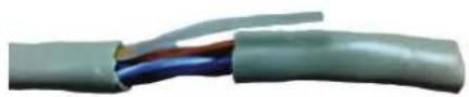
natural_image
Close-up of a multi-core electrical cable with visible color bands (no text or symbols)natural_image
Close-up of a multi-colored electrical cable with visible color bands (no text or symbols)
natural_image
Close-up of a multi-colored electrical cable with visible wires (no text or symbols)natural_image
Close-up of a hand holding a small electronic component with a multicolored chip (no visible text or symbols)natural_image
Close-up of a transparent electrical connector with internal wiring and connectors (no text or symbols visible)natural_image
Close-up of hands using a wire to apply a component, no visible text or symbolsnatural_image
Close-up of a transparent electrical connector with visible internal wiring and color bands (no text or symbols)Advertencias
natural_image
Green and black wire crimping tool (no text or symbols visible)natural_image
Close-up of a transparent plastic electrical connector with a yellow internal component (no visible text or symbols)RJ45 PINS
Port Connector

Pin 1 Pin 8 Pin 8 Pin 1
natural_image
Close-up of a white cylindrical object placed next to a ruler, showing measurement markings (no text or symbols visible)
natural_image
Close-up of a multi-core electrical cable with visible color bands (no text or symbols)natural_image
Close-up of a multi-colored cable with visible color bands (no text or symbols)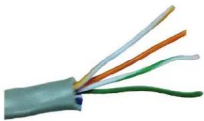
natural_image
Close-up of a multi-colored electrical cable with visible wires (no text or symbols)text_image
Conector 1 Conector 2 1 2 3 4 5 6 7 8 W/O O W/G G 1 2 3 4 5 6 7 8 W/O O W/G G Anatural_image
Close-up of a finger holding a small electronic component (no visible text or symbols)natural_image
Close-up of a transparent electrical connector with internal wiring and a close-up view showing internal structure (no text or symbols visible)natural_image
Close-up of hands using a wire to apply plastic components on a mechanical clamp (no visible text or symbols)natural_image
Close-up of a transparent electrical connector with visible internal wiring and color-coded wires (no text or symbols)Avisos
natural_image
Green and black wire crimping tool (no text or symbols visible)natural_image
Close-up of a transparent plastic electrical connector with a yellow internal component (no text or symbols visible)RJ45 PINS
Port Connector
Pin 1 Pin 8 Pin 8 Pin 1
natural_image
Close-up of a white plastic strip being cut by a ruler, showing measurement markings (no text or symbols on the object itself)
natural_image
Close-up of a multi-core electrical cable with visible color bands (no text or symbols)natural_image
Close-up of a multi-colored electrical cable with visible color bands (no text or symbols)
natural_image
Close-up of a multi-colored electrical cable with visible wires (no text or symbols)text_image
Conector 1 Conector 2 W/O O W/G G Anatural_image
Close-up of a hand holding a small electronic component with a multicolored chip (no visible text or symbols)natural_image
Close-up of a transparent electrical connector with internal wiring and a close-up view showing internal components (no text or symbols visible)natural_image
Close-up of hands using a wire to apply a component, no visible text or symbolsnatural_image
Close-up of a transparent electrical connector with visible internal wiring and color bands (no text or symbols)Предупреждения
natural_image
Green and black wire crimping tool (no text or symbols visible)natural_image
Close-up of a transparent plastic electrical connector with a yellow internal component (no visible text or symbols)RJ45 PINS
Port Connector


Pin 1 Pin 8 Pin 8 Pin 1
Процедура монтажа
natural_image
Close-up of a white plastic object being cut by a ruler, showing measurement markings (no text or symbols visible)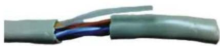
natural_image
Close-up of a multi-core electrical cable with visible color bands (no text or symbols)natural_image
Close-up of a multi-colored cable with visible color bands, no text or symbols present
natural_image
Close-up of a multi-colored electrical cable with visible wires (no text or symbols)text_image
1 2 3 4 5 6 7 8 W/D O W/G G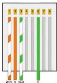
text_image
1 2 3 4 5 6 7 8 W/D D W/G GA
natural_image
Close-up of a hand holding a small electronic component, possibly a flexible capacitor or sensor, with no visible text or symbols.natural_image
Close-up of a transparent electrical connector with internal wiring and a close-up view of its cable (no text or symbols visible)natural_image
Close-up of hands using a wire to apply plastic components on a mechanical clamp (no visible text or symbols)natural_image
Close-up of a transparent electrical connector with visible internal wiring and color bands (no text or symbols)Uyarılar
natural_image
Green and black wire crimping tool (no text or symbols visible)natural_image
Close-up of a transparent plastic electrical connector with a small yellow component (no visible text or symbols)RJ45 PINS
Port Connector


Pin 1 Pin 8 Pin 8 Pin 1
Montaj prosedürü.
natural_image
Close-up of a white plastic strip being cut with a ruler, showing measurement markings (no text or symbols)
natural_image
Close-up of a multi-core electrical cable with visible color bands (no text or symbols)natural_image
Close-up of a multi-colored electrical cable with visible color bands (no text or symbols)
natural_image
Close-up of a multi-colored electrical cable with visible wires (no text or symbols)natural_image
Close-up of a hand holding a small electronic component with a multicolored chip (no visible text or symbols)natural_image
Close-up of a transparent electrical connector with internal wiring and a close-up view showing internal components (no text or symbols visible)natural_image
Close-up of hands using a wire to apply a component, no visible text or symbolsnatural_image
Close-up of a transparent electrical connector with visible internal wires and color bands (no text or symbols)Ostrzeżenia
natural_image
Green and black wire crimping tool (no text or symbols visible)natural_image
Close-up of a transparent plastic electrical connector with gold pins (no text or symbols visible)RJ45 PINS
Port Connector


Pin 1 Pin 8 Pin 8 Pin 1
Procedura montażu.
natural_image
Close-up of a white plastic object being cut by a ruler, showing measurement markings (no text or symbols visible)
natural_image
Close-up of a multi-core electrical cable with visible color bands (no text or symbols)natural_image
Close-up of a multi-colored cable with visible color bands, no text or symbols present
natural_image
Close-up of a multi-colored electrical cable with visible wires (no text or symbols)natural_image
Close-up of a hand holding a small electronic component with a green and yellow stripe (no text or symbols visible)natural_image
Close-up of a transparent electrical connector with internal wiring and a close-up view showing internal structure (no text or symbols visible)natural_image
Close-up of hands using a wire to apply a component, no visible text or symbolsnatural_image
Close-up of a transparent plastic electrical connector with visible internal wiring and color bands (no text or symbols)IT Montaggio posto esterno Art. 4894I/4894IM
EN Mounting external unit Art. 4894I/4894IM
FR Montage d'un poste extérieur réf. 4894I/4894IM
NL Montage entreepaneel Art. 4894I/4894IM
DE Einbau Außensprechstelle Art. 4894I/4894IM
ES Montaje de la placa externa Art. 4894I/4894IM
PT Montagem do posto externo Art. 4894I/4894IM
○ Монтаж внешнего блока арт. 4894I/4894IM
○ Dış ünitenin Par. 4894I/4894IM montajı
○ Montaż kasety bramowej Art. 4894I/4894IM
IT Lasciare in posizione la protezione di impianto
EN Leave the system protection device in position
FR Laisser en position la protection de l'installation
NL Laat de installatiebeveiliging op zijn plaats
DE Die Sicherung der Anlage nicht entfernen
ES Dejar colocada la protección de la instalación
PT Deixar a protecção da instalação em posição
RU Оставьте на месте защитную систему устройства
TR Sistem korumasını konumunda bırakın
PL Pozostawić zabezpieczenia instalacji na miejscu

text_image
165 cm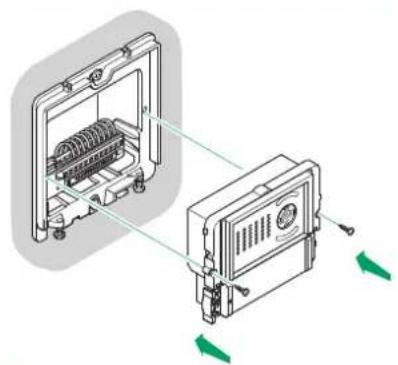
natural_image
Technical diagram showing two mechanical components with directional arrows indicating movement or assembly (no text or symbols present)2
1
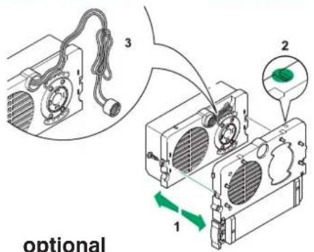
IT Regolazioni microfono e telecamera
EN Microphone and camera adjustment
FR Réglages micro et caméra
NL Instellingen microfoon en camera
DE Mikrophon- und Kamera-Einstellungen
ES Regulaciones del micrófono y de la telecámara
PT Regulação do microfone e da câmara
RU Регулировка микрофона и камеры
TR Mikrofon ve kamera ayarları
PL Regulacja mikrofonu i kamery
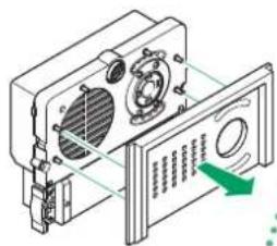
text_image
Technical diagram showing a device with labeled components and a green arrow indicating a directional flow or movement.optional
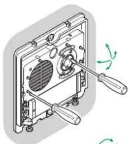
natural_image
Technical illustration of a mechanical assembly with two tools and a fan component (no text or symbols)
natural_image
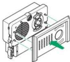
Isometric technical diagram of a device with labeled components and a green arrow indicating a specific section (no text or symbols present)IT Posizione alternativa del microfono
EN Alternative microphone position
FR Position alternative du micro
NL Alternatieve positie van de microfoon
DE Alternative Position des Mikrofons
ES Posición alternativa del micrófono
PT Posição alternativa do microfone
RU Альтернативное расположение микрофона
TR Mikrofon için alternatif konum
PL Alternatywna pozycja mikrofonu
text_image
optionaloptional
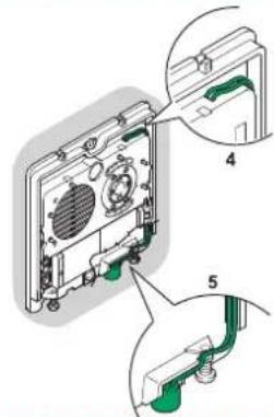
text_image
Technical diagram showing exploded view of a device with labeled parts 4 and 5, including internal components and green connectors.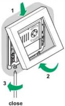
text_image
1 2 3 close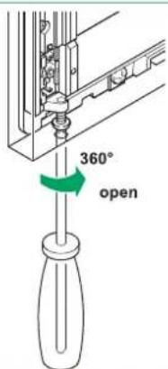
text_image
360° open3
IT Inserimento cartellini portanome
EN Inserting nameplates
FR Installation étiquettes porte-noms
NL Montage naambordjes
text_image
QR code image containing encoded data, no visible human-readable text
Comelit®
Passion.Technology.Design.