HFX7000M - Intercom COMELIT - Free user manual and instructions
Find the device manual for free HFX7000M COMELIT in PDF.

| Product Type | Hands-free video intercom kit |
| Brand | Comelit |
| Model | HFX7000M |
| Monitor dimensions (W × H × D) | 115 × 160 × 21.5 mm |
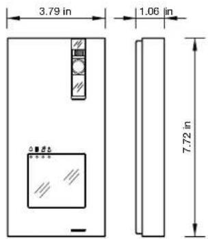
| Outdoor station dimensions (W × H × D) | 96.2 × 196.2 × 27 mm |
| Power supply | 110-240 V~ via BUS 1209/4 power supply |
| Monitor consumption | 10 W max |
| Outdoor station consumption | 8 W max |
| Display | 4.3" color LCD |
| Display resolution | 480 × 272 pixels |
| Camera | 4" CMOS, 600TVL resolution (640 × 480), 98° diagonal angle |
| Monitor operating temperature | 5 °C to 40 °C |
| Outdoor station operating temperature | -25 °C to +55 °C |
| Main functions | Call, video door entry, door opener, intercom, paging, auto-on, privacy mode, doctor function, automatic answer |
| Max number of monitors | 4 |
| Max number of outdoor stations | 4 |
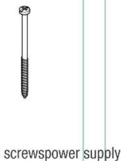
| Package contents | EX-DSM outdoor station, EX-7000H monitor, 1209/4 BUS power supply, nameplate labels, technical manual, screws and wall plugs |
| Care and cleaning | Clean with a soft, dry cloth. Do not use abrasive products or water. |
| Safety | Do not expose to rain or moisture. Disconnect if not used for a long time. Repair by qualified personnel only. |
| Warranty | 2 years manufacturer's warranty |
Frequently Asked Questions - HFX7000M COMELIT
User questions about HFX7000M COMELIT
0 question about this device. Answer the ones you know or ask your own.
Ask a new question about this device
Download the instructions for your Intercom in PDF format for free! Find your manual HFX7000M - COMELIT and take your electronic device back in hand. On this page are published all the documents necessary for the use of your device. HFX7000M by COMELIT.
USER MANUAL HFX7000M COMELIT
Complete technical manual for
Single-User Kit HFX-7000M
Manuel technique comple
Manual technique integral
del Kit de Nombre HFX-7000M
Contents
- Contents of the package 4
2. Parts identification.. 5
2.1 EX-DSM EXTERNAL UNIT 5
2.2 EX-7000H MONITOR 6
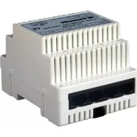
2.3 1209/4 BUS POWER SUPPLY
2.4 PARTS IDENTIFICATION FOR EXPANSION
2.4.1 1405 Video Door Expander
3. System installation.. 8
3.1 OPERATING DISTANCES AND SYSTEM LAYOUT 8
3.1.1 Single-User Kit Art. HFX-7000M 8
3.1.2 Maximum Expansion Monitors in Daisy Chain connection 8
3.1.3 Full System Expansion Diagram 9
BASIC SINGLE-USER KIT
STANDARD INSTALLATION 10
EXPANDED SINGLE-USER KIT
MAXIMUM EXPANSION IN DAISY CHAIN CONNECTION 11
EXPANDED SINGLE-USER KIT
MAXIMUM EXPANSION 12
MULTI-USERxpansion
TWO-USERS EXPANSION. 13
MULTI-USEREXPANSION
FOUR-USERS EXPANSION 14
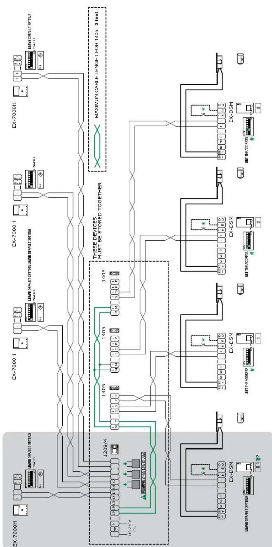
FULL MULTI-USERxpansion
FOUR-USERS EXPANSION WITH FOUR EXTERNAL UNIT. 15
BASIC SINGLE-USER KIT
TV INTERFACE (ART. 1257) CONNECTION 16
BASIC SINGLE-USER KIT
ADDITIONAL RELAY MODULE (ART. 1256) CONNECTION 17
BASIC SINGLE-USER KIT
FULL MULTI-USERxpansion
FOUR-USERS EXPANSION WITH FOUR EXTERNAL UNIT AND CCTV
CAMERA INTERFACE (ART. 1409) 19
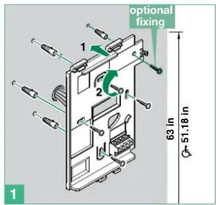
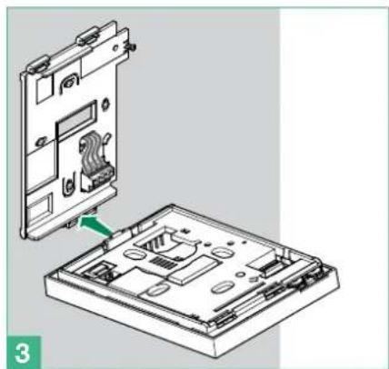
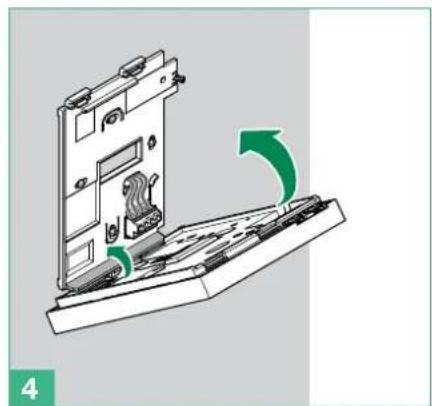
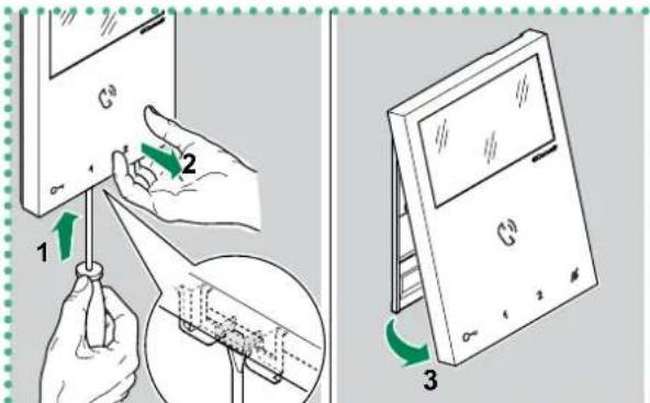
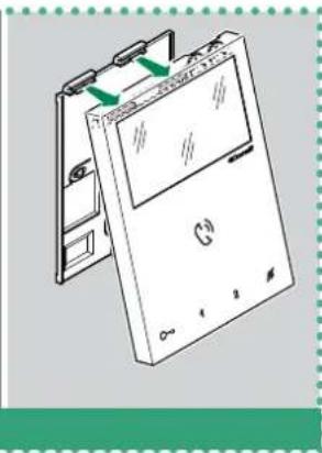
3.2 ASSEMBLY MINI HANDSFREE ART. EX-7000H INTERNAL UNIT.. 20
3.3 INSTALLATION OF EXTERNAL UNIT ART. EX-DSM 21
3.3.1 How to change the nameplate of the external unit Art. EX-DSM 22
4. Additional features programming 23
4.1 ADDRESSING ART. EX-7000H BY MEANS OF DIP SWITCH 23
4.2 CONFIGURATION CAPACITIVE-TOUCH KEYS ART. EX-7000H 23
4.2.1 Preset function 23
4.2.2 Quick programming 23
4.2.3 Special key programming 24
4.2.3.1 HOW TO PROGRAM THE ACTUATOR FUNCTION 24
4.2.3.2 HOW TO PROGRAM THE INTERCOM FUNCTION 24
4.2.3.3 HOW TO PROGRAM THE PAGING FUNCTION 25
4.2.3.4 HOW TO PROGRAM THE SELF IGNITION FUNCTION 25
4.2.3.5 HOW TO PROGRAM THE DOCTOR FUNCTION 26
4.3 RESET PROGRAMMING ART. EX-7000H 27
4.4 RANGE PROGRAMMING ART. EX-7000H 27
4.5 MONITOR RINGTONE SELECTION ART. EX-7000H. 28
4.6 CONFIGURATION EX-DSM 28
4.6.1 External unit addressing.. 28
4.6.2 Function programming 28
4.6.3 Special function programming 29
4.7 ACTUATOR RELAY MODULE ART. 1256. 31
4.7.1 Parts description 31
4.7.2 Functions 31
4.8 TV INTERFACE ART. 1257 32
4.8.1 Parts description 32
4.8.2 Functions 32
4.9 CCTV CAMERA INTERFACE ART. 1409 33
4.9.1 Parts description 33
4.9.2 Operation 33
4.9.2.1 PROGRAMMING THE NUMBER OF CAMERAS CONNECTED....33
4.9.2.2 FUNCTION 1: GENERIC ACTUATOR MODE 33
4.9.2.3 FUNCTION 2: ACTUATOR WITH CODE MODE... 33
4.9.2.4 COMPATIBILITY TABLE 34
5. System function 35
5.1 PERFORMING CALLS 35
5.1.1 How to call from the external unit 35
5.1.2 How to answer a call from an internal unit 35
5.1.3 How to transmit a call to the other internal units.. 35
5.1.4 How to answer a call from an internal unit 35
5.2 PAGING CALL 36
5.2.1 How to Initiate a paging call 36
5.2.2 How to answer a paging call 36
5.3 SELF-IGNITION FUNCTION 36
5.3.1 How to display on the monitor the image transmitted from the CCTV camera 36
5.4 LOCK RELEASE FUNCTION 37
5.5 ACTIVATION / DEACTIVATION PRIVACY MODE 37
5.6 ACTIVATION / DEACTIVATION DOCTOR FUNCTION 37
5.7 ACTIVATION / DEACTIVATION AUTOMATIC ANSWER MODE 37
5.8 BRIGHTNESS CONTROL 38
5.9 LOUDSPEAKER VOLUME CONTROL 38
6. Technical specification 39
6.1 EX-7000H MAIN MONITOR 39
6.2 EX-DSM EXTERNAL UNIT 39
6.3 1209/4 BUS POWER SUPPLY 39
6.4 ACTUATOR RELAY MODULE ART. 1256 39
6.5 TV INTERFACE ART. 1257 39
6.6 REMOTE CAMERA MODULE ART. 1409 39
6.7VIDEODOOREXPANDERART.1405 39
7. Appendix 40
7.1WARNING 40
7.2 IMPORTANT SAFETY INSTRUCTIONS 40
7.3 FCC CLASS B NOTICE 41
7.4 GENERAL PRODUCT WARRANTY: 41
Thank you for purchasing the hands free kits Art. HFX-7000M!
This intercom system uses 2-wire installation and allows you to identify and communicate with callers at the door, from the security and convenience of any room in your home or office. Visitors activate the system by pressing a call pad on the external unit, which sounds a doorbell chime as well as turning on the inside "hands free video monitor".
A two-way intercom then lets you speak with visitors after first visually identifying them.
It consists of a hands free monitor station and an external unit.
This kit is capable of expanding up to a total of 4 indoor monitors and 4 external units.
1. Contents of the package
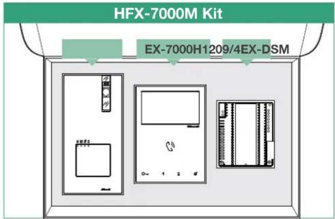
EX-DSM - External unit
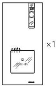
external unit
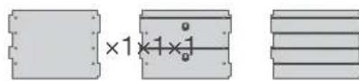
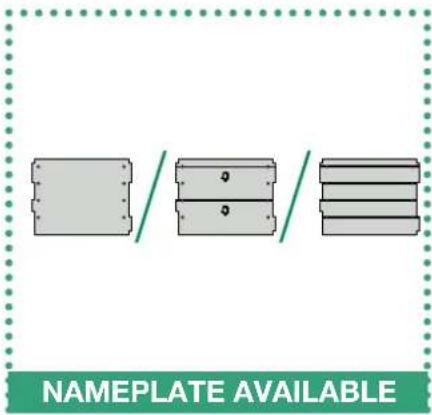
Replaceable nameplates
for 1 user
for 2 users
for 4 users
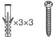
dry wall
anchors
screws
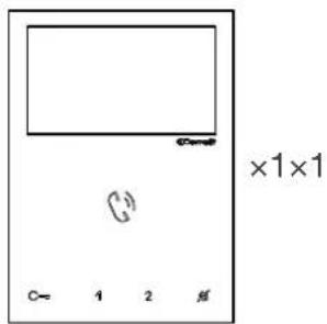
EX-7000H - Monitor
monitor backplate

dry wall
anchors
rews
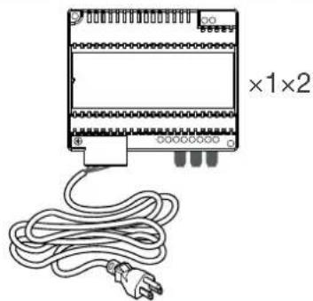
1209/4 - BUS Power supply Technical
manual
2. Parts identification
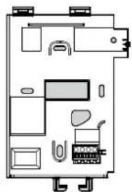
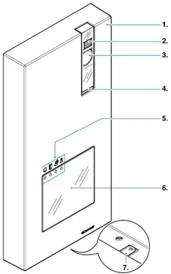
2.1 EX-DSM EXTERNAL UNIT
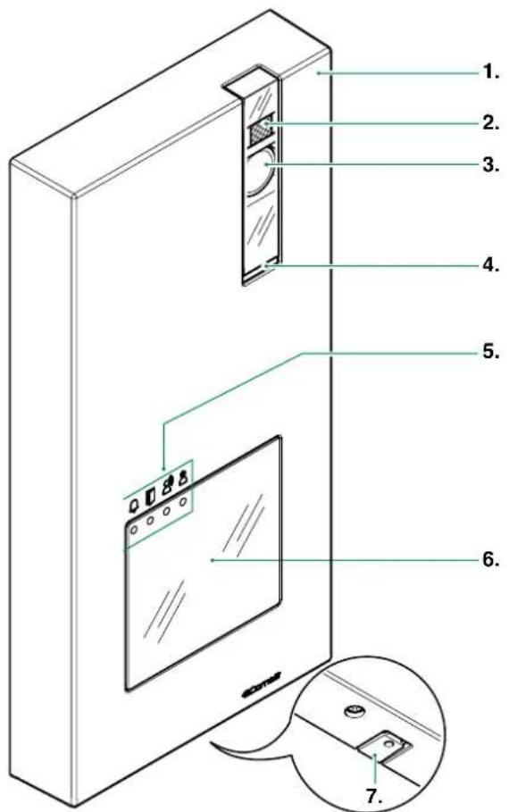
- Die-cast aluminium cover
- Camera lighting LED
- Wide-angle colour camera
- Loudspeaker
- Indicator LED:

Ca

io enabled.

rele

se enabledem engage
- Transparent label-holder front panel

For instructions on replacing the nameplate, see page 22
3.3.1 How to change the nameplate of the external unit Art.
EX-DSM".
For instructions on enabling the buttons for 2/4 users, see
page 29 "4.6.3 Special function programming".
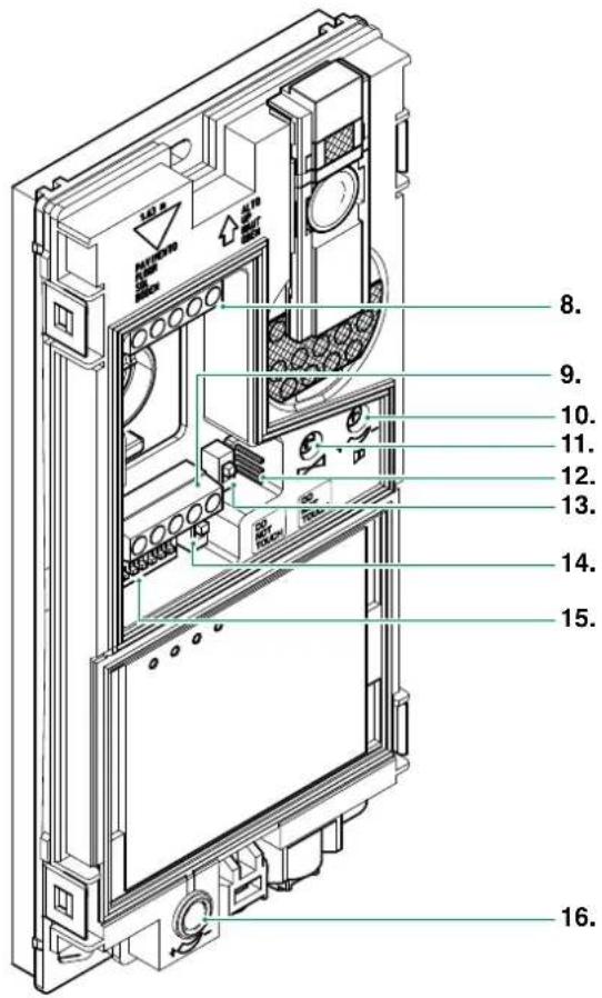
-
Microphone
-
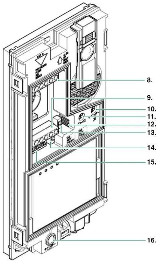
Terminal block M1
LL bus line connection
RTE timed local lock-release input
COM common input for RTE and DO contacts
DO door open indication input
- Terminal block M2
SE- connection for electric door lock
SE+ connection for electric door lock
NC relay normally closed contact
NO relay normally open contact
C relay common contact
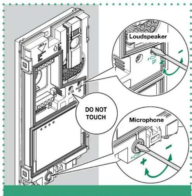
- Loudspeaker volume control
- Audio balance (Factory default do not touch)
- JP1 enable RC network for door lock filter on relay contacts

ON CONTACTS C. NO. ON CONTACTS C. NC.

DISABLED: CLEAN CONTACT
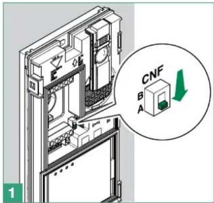
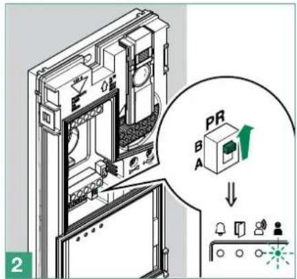
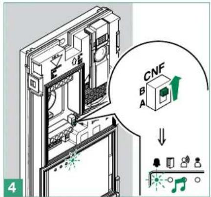
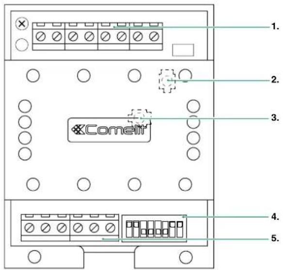
- CNF programming confirmation switch
- PR programming input/output switch
- S1 DIP SWITCH for function programming
- Microphone volume control
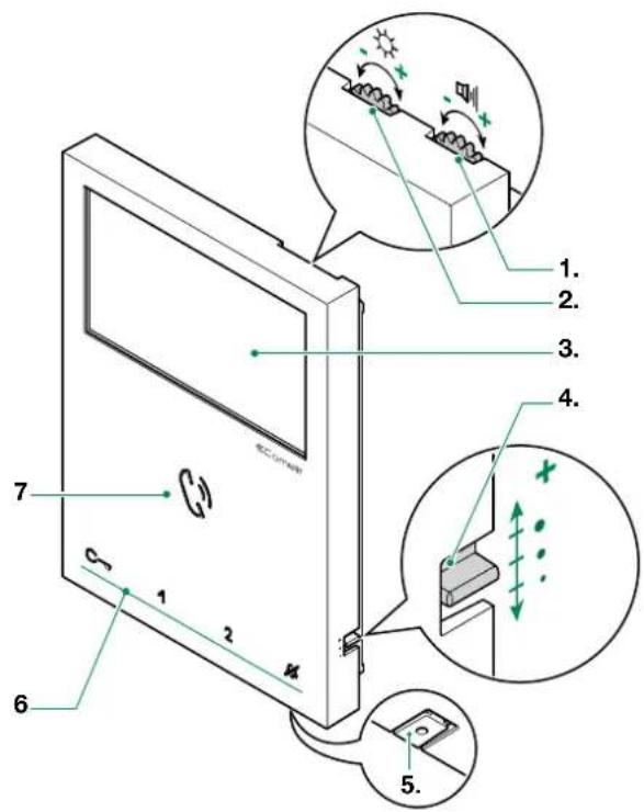
- Loudspeaker volume control
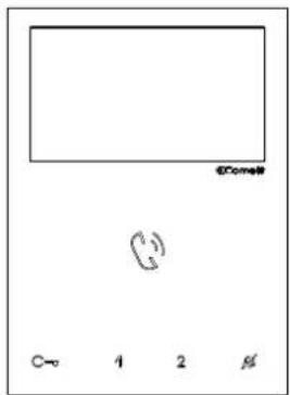
- Brightness control
- 4.3^ Color LCD Screen
- Call volume adjustment (high - medium - low)
- Microphone
- Capacitive-touch keys
- Speaker and audio activation key / Paging call key
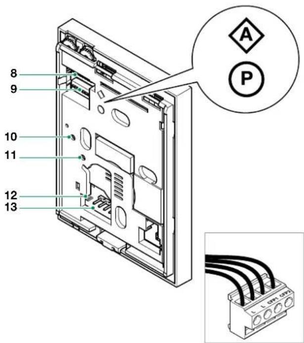
- S1 Micro-switches for user code setting
- S2 Micro-switches for programming keys and functions
DIP 1-2-3-4 for key function programming
DIP 5-6 access to programming
DIP 7 unused
DIP 8 leave default setting (OFF)
- Factory setting - DO NOT CHANGE!
- Factory setting - DO NOT CHANGE!
- CV 5 Video closing jumper
- Pin for securing terminal block
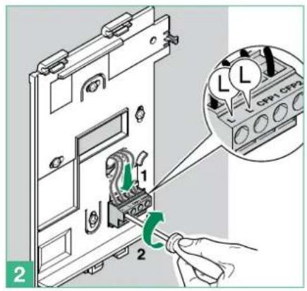
Terminal block for system connection:
LL Bus line connection terminals
CFP1 CFP2 Outside door call input
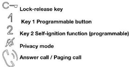
Capacitive-touch key description:
Press the desired key once to activate the function associated with it.
Wait for approximately 1 sec. before pressing the same key again. Pressing the same key several times in quick succession will cancel the command.
Lock-release key
Key 1 Actuator function (programmable)
Key 2 Self-ignition function (programmable)
Privacy key
Speaker and audio activation key / Paging call key
Indicator LED description:
Lock-release LED
slow continuous flashing: door open
1 flash after pressing: door opening confirmation
continuous flashing: call in progress
1 flash after programmation: Confirm "Key programming executed"
Privacy LED (red)
steady: privacy function enabled
3 flashes (every 5 sec.); doctor function enabled
continuous flashing: device in programming mode
Audio key LED
steady (with call): audio activated
steady (idle): automatic answer activated
continuous flashing: incoming call
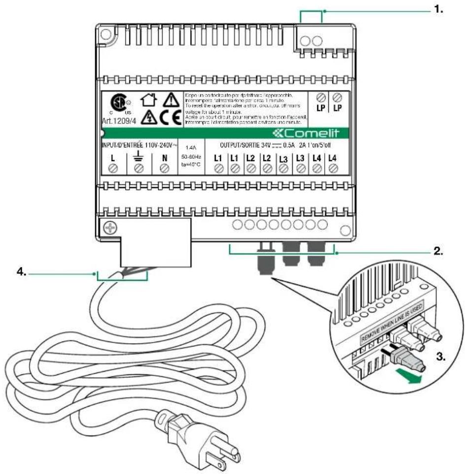
- LP LP external unit connection
-
L1 | L1 monitor connection 1
L2 | L2 monitor connection 2
L3 | L3 monitor connection 3
L4 | L4 monitor connection 4 -
Video closing jumpers (REMOVE WHEN LINE IS USED)
- L 1 N mains power input 110-240
2.4 PARTS IDENTIFICATION FOR EXPANSION
| ADDITIONAL INTERNAL UNIT | EX-7000H | The Art. EX-7000H is the Additional Internal Unit for Single-User Kits (see page 6 for further information) |
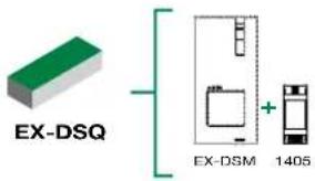
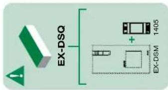
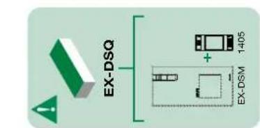
| ADDITIONAL EXTERNAL UNIT | EX-DSQ | The Art. EX-DSQ is the Additional External Unit for Single-User Kits and contains the external unit Art. EX-DSM (see page 5 for further information) and the Video Door Expander Art. 1405 (see "2.4.1 Video Door Expander 1405" for further information) |
2.4.1 Video Door Expander 1405
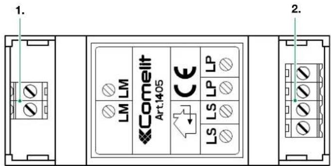
- LM LM Art. 1209/4 connection
- LS | LS additional external unit connection
LP | LP main external unit connection
3. System installation
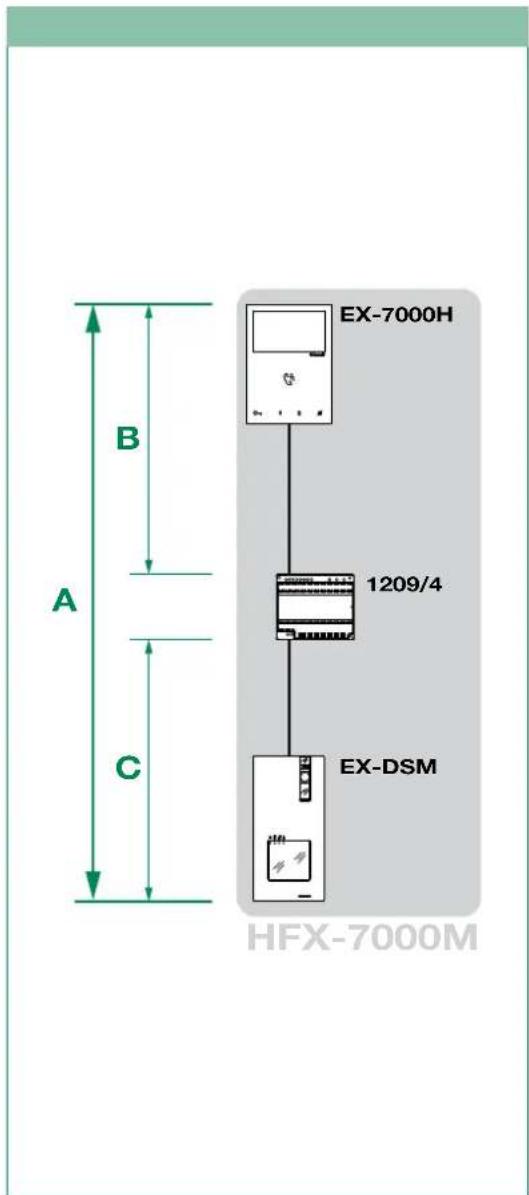
3.1 OPERATING DISTANCES AND SYSTEM LAYOUT
| Wire Assignment Wire Assignment Wire Type A MAX B MAX C MAX | |||||
| SINGLE PAIR CABLE | CAT5 24AWG | 1,115 feet (340 m) | 557 feet (170 m) | 557 feet (170 m) | |
| DOUBLE PAIR CABLE | CAT5 24AWG | 1,312 feet (400 m) | 656 feet (200 m) | 656 feet (200 m) | |
| MULTI PAIR CABLE FOLLOW THE COLORS SHOWN IN THE DIAGRAM! | CAT5 24AWG | 1,312 feet (400 m) | 656 feet (200 m) | 656 feet (200 m) | |
| NON-BRAIDED CABLE | AWG22 | 1,115 feet (340 m) | 557 feet (170 m) | 557 feet (170 m) | |
| NON-BRAIDED CABLE | AWG18 | 1,312 feet (400 m) | 656 feet (200 m) | 656 feet (200 m) | |
3.1.2 Maximum Expansion Monitors in Daisy Chain connection3.1.1 Sing
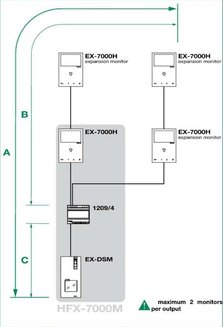

NOTE: This system is capable to expanding up to 4 external units and 4 internal units. For alternative application please consult our technical support engineer first.

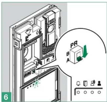
At the first connection on the riser, the internal units automatically acquire theirs sub-addresses. The LEDs and flash simultaneously for some seconds. After the procedure the LEDs will turn off.

The Art. EX-DSQ is the Additional External Unit for Single-User Kits and contains the external unit Art. EX-DSM and the Video Door Expander Art. 1405
3.1.3 Full System Expansion Diagram
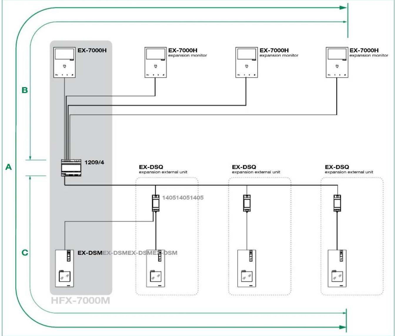
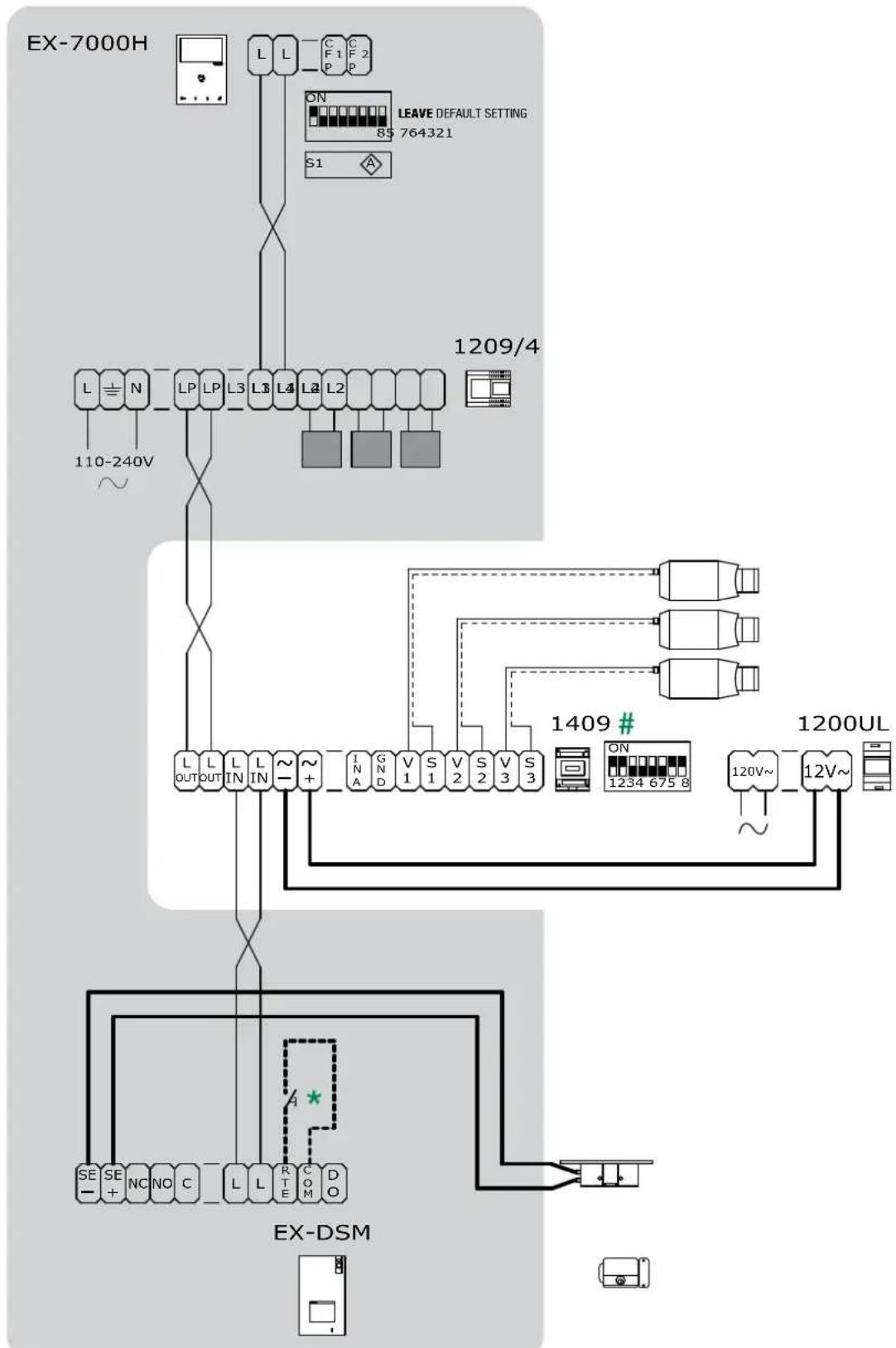
Basic single-user kit
STANDARD INSTALLATION
HFX-7000M
Wiring diagram: MNVK/039QCU
Expanded single-user kit
MAXIMUM EXPANSION IN DAISY CHAIN CONNECTION
Wiring diagram: MNVK/Q19U
Expanded single-user kit
MAXIMUM EXPANSION
HFX-7000M
| EXTERNAL UNIT ADDRESSING | ||||
| DIP 1 | DIP 2 | DIP 3 | CODE | |
| 0 | 0 | 0 | ON 12345678 | 0 (default) |
| 1 | 0 | 0 | ON 12345678 | 1 |
| 0 | 1 | 0 | ON 12345678 | 2 |
| 0 | 0 | 1 | ON 12345678 | 3 |
The addresses must be consecutive! correct:0,1,2,3/incorrect:0,1,3
- Local lock release button
Wiring diagram: MNVK/012BQCU
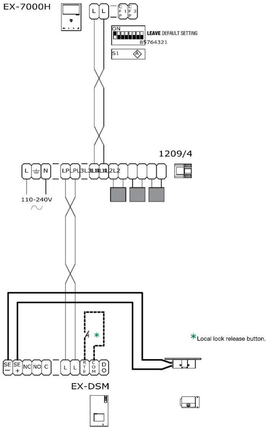
Multi-users expansion
TWO-USERS EXPANSION
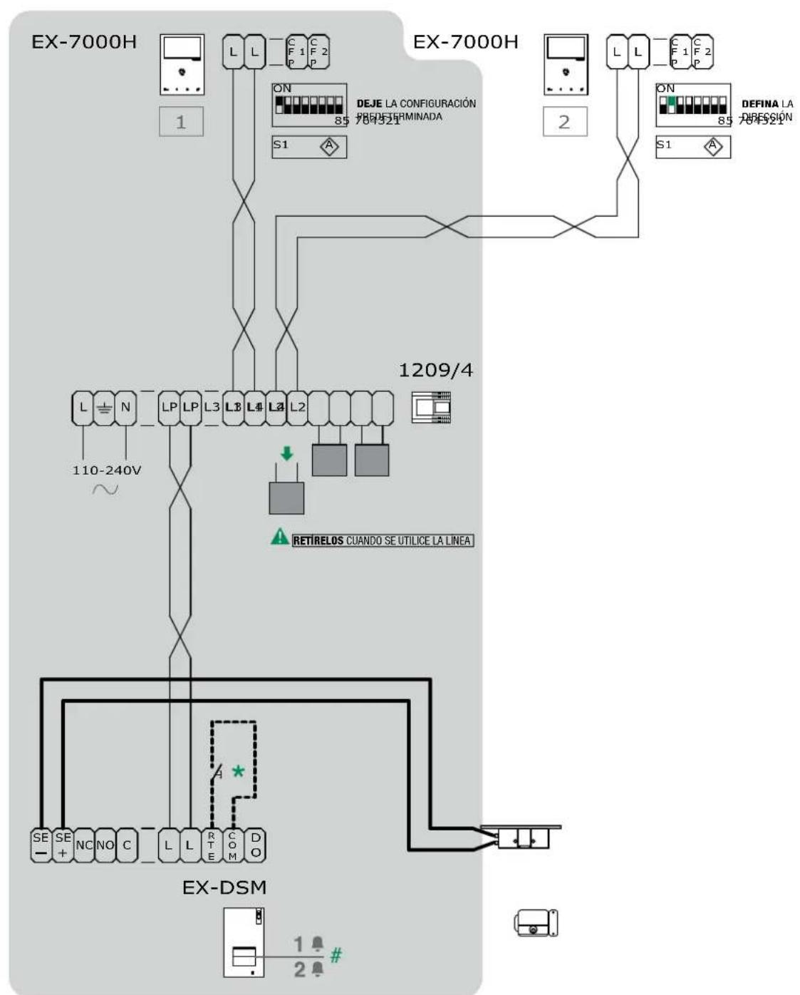
HFX-7000M
- Local lock release button.
For programming see page 29 "4.6.3 Special function programming"
Wiring diagram: MNVK/040QCU
Multi-users expansion
FOUR-USERS EXPANSION
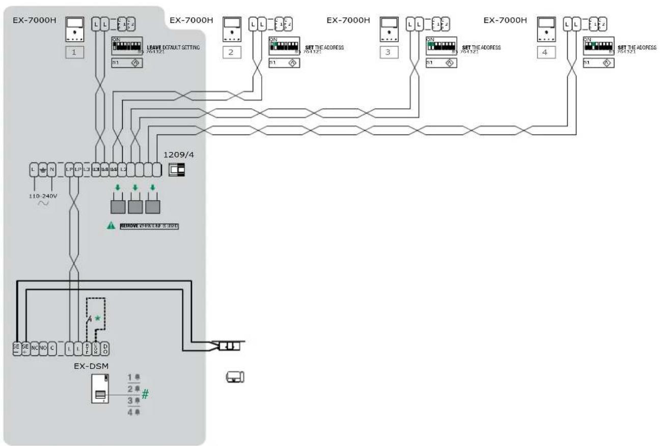
HFX-7000M
- Local lock release button.
For programming see page 29 "4.6.3 Special function programming"
Wiring diagram: MNVK/012AQCU
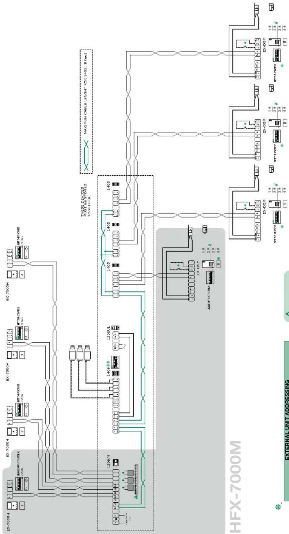
Full multi-users expansion
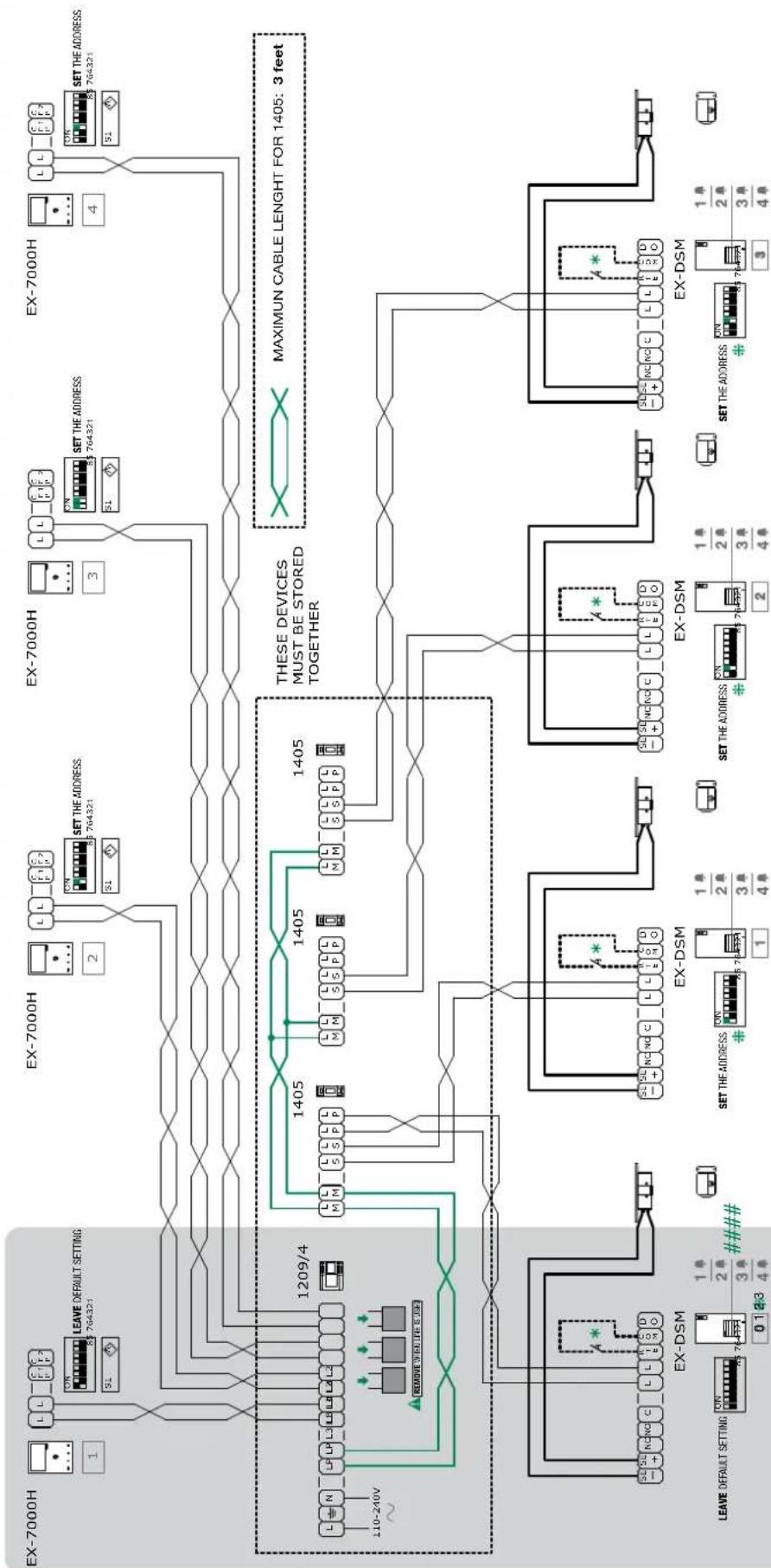
FOUR-USERxpansionWITHFOUR EXTERNALUNIT
HFX-7000M
| EXTERNAL UNIT ADDRESSING | ||||
| DIP 1 | DIP 2 | DIP 3 | CODE | |
| 0 | 0 | 0 | ON 12345678 | 0 (default) |
| 1 | 0 | 0 | ON 12345678 | 1 |
| 0 | 1 | 0 | ON 12345678 | 2 |
| 0 | 0 | 1 | ON 12345678 | 3 |
The addresses must be consecutive! correct:0,1,2,3 / incorrect:0,1,3
* Local lock release button.
For programming, see 29 "4.6.3 Special function programming"
Wiring diagram: MNVK/012CQCU
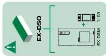
Basic single-user kit
TV INTERFACE (Art. 1257) CONNECTION
HFX-7000M
- Local lock release button.
For further information see page 32 "4.8 TV INTERFACE ART. 1257"
Wiring diagram: MNVK/07U
Basic single-user kit
ADDITIONAL RELAY MODULE (Art. 1256) CONNECTION
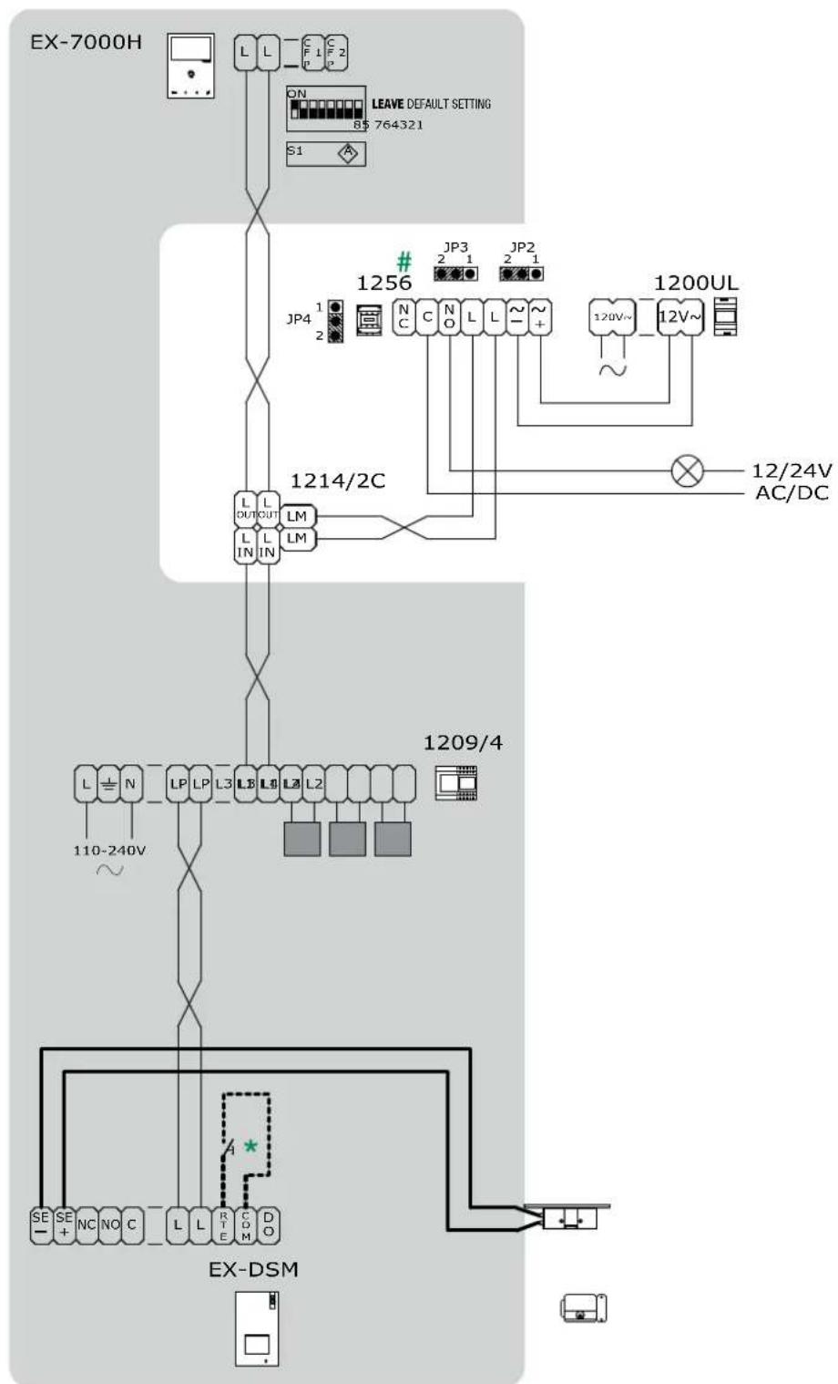
HFX-7000M
- Local lock release button.
For further information see page 31 "4.7 Actuator relay module Art. 1256"
Wiring diagram: MNVK/EQCU
Basic single-user kit
CCTV CAMERA INTERFACE (Art. 1409) CONNECTION
HFX-7000M
- Local lock release button.
For further information see page 33 "4.9 CCTV camera interface ART. 1409"
Wiring diagram: MNVK/015QCU
Full multi-users expansion
FOUR-USERS EXPANSION WITH FOUR EXTERNAL UNIT and CCTV CAMERA INTERFACE (Art. 1409)
| EXTERNAL UNIT ADDRESSING | ||||
| DIP 1 | DIP 2 | DIP 3 | CODE | |
| 0 | 0 | 0 | ON 12345678 | 0 (default) |
| 1 | 0 | 0 | ON 12345678 | 1 |
| 0 | 1 | 0 | ON 12345678 | 2 |
| 0 | 0 | 1 | ON 12345678 | 3 |
The addresses must be consecutive! correct:0,1,2,3 / incorrect:0,1,3
Wing diagram MNVK015BOCU

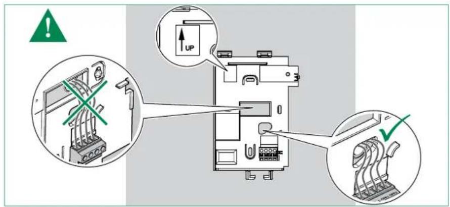

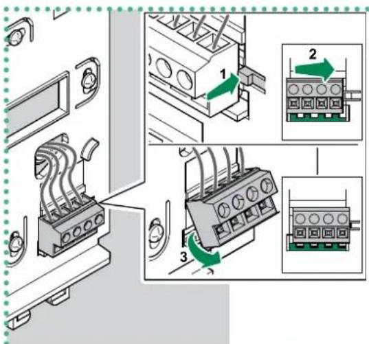
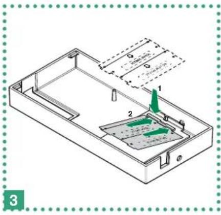
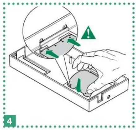
REMOVING THE TERMINAL
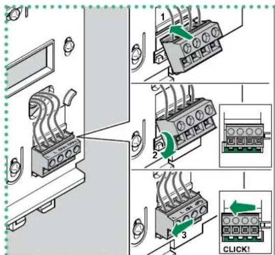
INSERTING THE TERMINAL
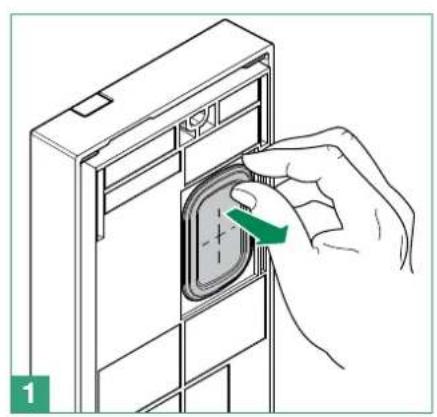
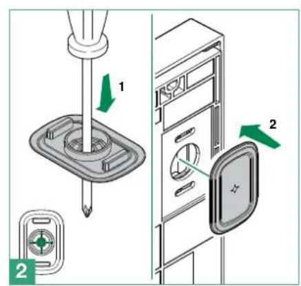

For instructions on changing the nameplate of the external unit, see the next section.
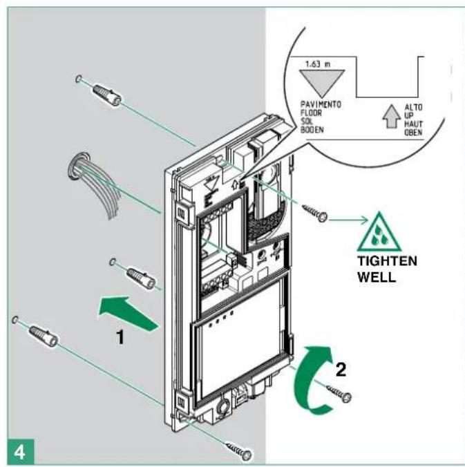
Before fixing the screw, make sure that you do not need to programme the external unit (see page 28 "4.6 Configuration EX-DSM") and make sure that the metal front panel does not rub against other metal parts, with consequent risk of damage to its insulating coating.

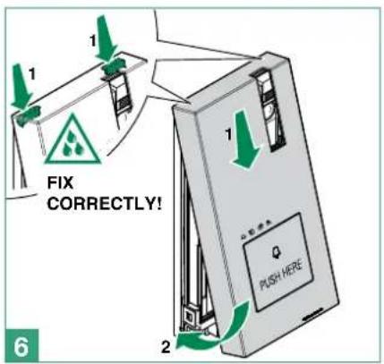
CAUTION! To ensure that the product remains water-tight: make sure that the fixing procedure is carried out correctly
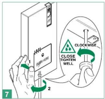
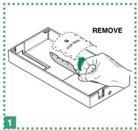
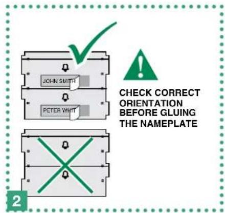
3.3.1 How to change the nameplate of the external unit Art. EX-DSM

Labels must be made of non-conductive material so as not to compromise the operation of the Capacitive-touch buttons.
It is possible download the free software (Art. 1235A) from the website www.comelitgroup.com to print the entrance panel name tags, using the adhesive pre-cut sheets available in our catalogue
4. Additional features programming
4.1 ADDRESSING ART. EX-7000H BY MEANS OF DIP SWITCH
Set the user codes on S1 DIP Switches as indicated in "TAB. A User code" on page 30.
4.2 CONFIGURATION CAPACITIVE-TOUCH KEYS ART. EX-7000H
4.2.1 Preset function
default
LEGEND
| C- | Lock-release function: can be used to activate the lock-release relay |
| A | Privacy function: can be used to enable or to disable the ringtone for calls from the external unit and paging. |
| C | Audio key function: can be used to activate a conversation with the external unit or to end a conversation. |
| ACT | Generic actuator function: can be used to activate the relay for a generic actuator installed within the system.Coded actuator function: can be used to activate the relay for a specific actuator installed within the system. |
| AI | Self-ignition function: can be used to receive images from the main external unit cameras (press the key again to cycle through several external unit) |
| D | Doctor function: can be used to enable automatic activation of the lock-release in response to a call from the external unit. |
| INT | Internal intercom function: can be used to make a call to the internal units with the same user code.General intercom to another user code: can be used to make a call to the internal units with another user code. |
| PAG | Internal paging function: can be used to make a paging call to the internal units with the same user code.General paging to another user code: can be used to make a paging call to the internal units with another user code. |
| NULL | No function |
| PROG | Programmed functions: in this DIP switch setting, the buttons control the programmed functions; the NON-programmed buttons control functions referred to on line 0000 |
4.2.2 Quick programming
For the quick programming of the following functions:
- generic actuator (ACT),
- internal intercom calls (INT),
- internal paging calls (PAG),
Self ignition main external unit (AI),
Doctor function (D)
1 Set the S2 DIP switches combination corresponding to the functions that you want to programme for ALL KEYS as shown in the "PRESET FUNCTION TABLE".
| For example choose $2 DIP switches combination: | |||
| DIP 1 | DIP 2 | DIP 3 | DIP 4 |
| 0 | 1 | 0 | 0 |
| C- | P1 | P2 | ||
| PAG / | C- | INT | AI |
4.2.3 Special key programming
If the preset function (see page 23 "4.2.1 Preset function") do not reflect requirements, EACH KEY can be programmed differently by carrying out the steps below.
Special key programming allow to programm the following functions:
- generic actuator and coded actuator (ACT),
- internal intercom calls and general intercom calls to another user code (INT),
- internal paging calls and general paging to another user code (PAG),
Self ignition main external unit (AI), - Doctor function (D)
4.2.3.1 HOW TO PROGRAM THE ACTUATOR FUNCTION
| √ | Take note of the S1 setting and restore it when programming is complete | |||||||
| 1 Enter programming mode → Set S2 DIP switch 5-6 to the combination 01 → the privacy LED flashes | S2 ON 12345678 ⇒ | |||||||
| 2 | 1. Choose the function: refer to the following table and select a S2 DIP switches combination in which the actuator function (ACT) is listed for the keys you wish to program. | Example For P2= generic actuator S2 ON 12345678 S1 ON 12345678 | ||||||
| DIP S2 | KEY PROGRAMMING | |||||||
| DIP 1 | DIP 2 | 3 DIP 4 | ||||||
| 0000ACT | P1 P2 | |||||||
| 1100ACT | ||||||||
| 0010ACTACT | ||||||||
| 1010ACT | ||||||||
| 1111PROG | ||||||||
| 2. Addressing: → for generic actuator set S1 DIP switches to the combination 11111111 → for coded actuator set S1 DIP switches with the desired address in accordance with "TAB. A User code" on page 30. | ||||||||
| 3 Select the key to be associated with the function → Press and release the key to be associated with the function → the lock-release LED lights up → a confirmation tone will sound. | ||||||||
| 4 Exit programming mode → To exit programming mode, set S2 DIP switches 5-6 to the combination 00 → the privacy LED switches off | key ON 12345678 ⇒ | |||||||
| 5 When programming is complete, → Set S2 DIP switches 1-2-3-4 to the combination 1111 (PROG setting). In this DIP switch setting, the keys control the programmed functions; the NON-programmed keys control functions referred to on line 0000 (see the table above). → Restore the user code setting on S1, see "TAB. A User code" on page 30. | ON 12345678 ON 12345678 | |||||||
4.2.3.2 HOW TO PROGRAM THE INTERCOM FUNCTION
| √ | Take note of the S1 setting and restore it when programming is complete | |||||||
| 1 Enter programming mode → Set S2 DIP switch 5-6 to the combination 01 → the privacy LED flashes | ||||||||
| 2 | 1. Choose the function: refer to the following table and select a S2 DIP switches combination in which the intercom function (INT) is listed for the keys you wish to program. | Example For P1= general intercom to user code 3 S2 ON 12345678 ON 12345678 | ||||||
| DIP S2 | KEY PROGRAMMING | |||||||
| DIP 1 | DIP 2 | DIP 3 | DIP 4 | P1 | P2 | |||
| 0 | 1 | 0 | 0 | INT | ||||
| 1 | 0 | 1 | 0 | INT | ||||
| 1 | 0 | 1 | 1 | INT | INT | |||
| 1 | 1 | 1 | 1 | PROG | ||||
| 2. Addressing: → for internal intercom set S1 DIP switches with the same user code of the internal unit. → for general intercom to another user code set S1 DIP switches with the desired address in accordance with “TAB. A User code” on page 30. | ||||||||
| 3 Select the key to be associated with the function Press and release the key to be associated with the function the lock-release LED lights up a confirmation tone will sound. | key ⇒ |
| 4 Exit programming mode To exit programming mode, set S2 DIP switches 5-6 to the combination 00 the privacy LED switches off | S2 ON 12345678 ⇒ |
| 5 When programming is complete, Set S2 DIP switches 1-2-3-4 to the combination 1111 (PROG setting). In this DIP switch setting, the keys control the programmed functions; the NON-programmed keys control functions referred to on line 0000 (see the table above). Restore the user code setting on S1, see “TAB. A User code” on page 30. | S2 ON 12345678 ON 12345678 |
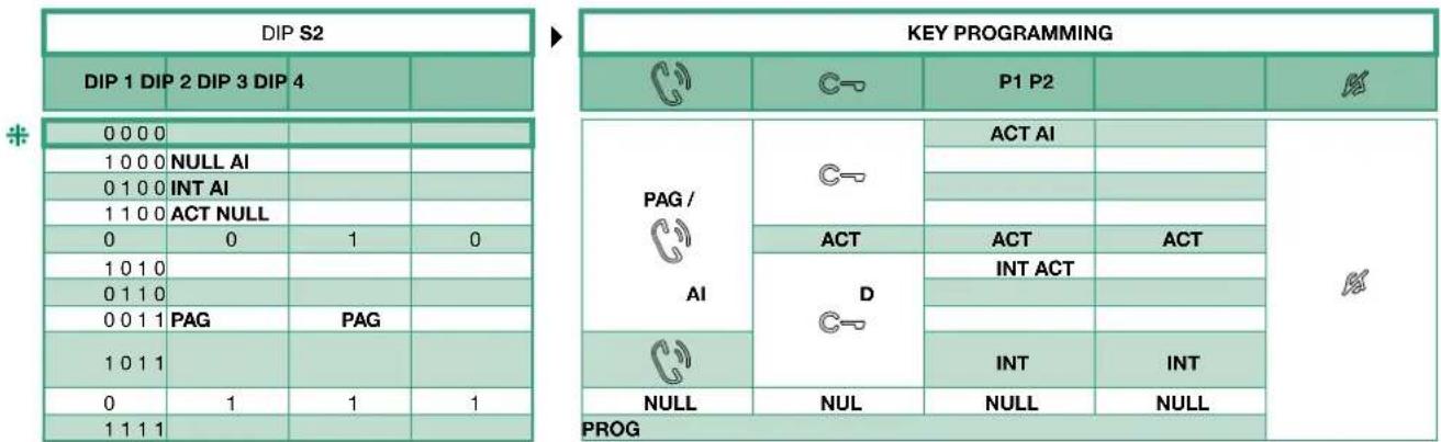
4.2.3.3 HOW TO PROGRAM THE PAGING FUNCTION
| √ | Take note of the S1 setting and restore it when programming is complete | |||||||
| 1 Enter programming mode → Set S2 DIP switch 5-6 to the combination 01 → the privacy LED flashes | S2 ON 12345678 → | |||||||
| 2 | 1. Choose the function: refer to the following table and select a S2 DIP switches combination in which the paging function (PAG) is listed for the keys you wish to program. | Example For = general paging to user code 3 S2 ON 12345678 S1 ON 12345678 | ||||||
| DIP S2 | KEY PROGRAMMING | |||||||
| DIP 1 | DIP 2 | DIP 3 | PAG / | C-O | P1 P2 | |||
| 0000 | ||||||||
| 1000 | ||||||||
| 0100 | ||||||||
| 1100 | ||||||||
| 0010 | ||||||||
| 1010 | ||||||||
| 0110 | ||||||||
| 0011 | PAG PAG | |||||||
| 1011 | ||||||||
| 0111 | ||||||||
| 1111 | PROG | |||||||
| 2. Addressing: → for internal paging set S1 DIP switches with the same user code of the internal unit. → for general paging to another user code set S1 DIP switches with the desired address in accordance with "TAB. A User code" on page 30. | ||||||||
| 3 Select the key to be associated with the function → Press and release the key to be associated with the function → the lock-release LED lights up → a confirmation tone will sound. | ||||||||
| 4 Exit programming mode → To exit programming mode, set S2 DIP switches 5-6 to the combination 00 → the privacy LED switches off | S2 ON 12345678 → | |||||||
| 5 When programming is complete, → Set S2 DIP switches 1-2-3-4 to the combination 1111 (PROG setting). In this DIP switch setting, the keys control the programmed functions; the NON-programmed keys control functions referred to on line 0000 (see the table above). → Restore the user code setting on S1, see "TAB. A User code" on page 30. | S2 ON 12345678 S1 ON 12345678 | |||||||
4.2.3.4 HOW TO PROGRAM THE SELF IGNITION FUNCTION
| √ | Take note of the S1 setting and restore it when programming is complete | |||||||
| 1 Enter programming mode ► Set S2 DIP switch 5-6 to the combination 01 ► the privacy LED flashes | S2 ON 12345678 ⇒ | |||||||
| 2 | 1. Choose the function: refer to the the following table and select a S2 DIP switches combination in which the self ignition function (AI) is listed for the keys you wish to program. | |||||||
| DIP S2 | KEY PROGRAMMING | Example For P1= self-ignition function S2 ON 12345678 | ||||||
| DIP 1 | DIP 2 | DIP 3 | DIP 4 | |||||
| 0000AI | ||||||||
| 1000AI | ||||||||
| 0100AI | ||||||||
| 0110AI | ||||||||
| 1111PROG | ||||||||
| 2. Addressing: → for self-ignition function don't set S1 DIP switches | ||||||||
| 3 Select the key to be associated with the function → Press and release the key to be associated with the function → the lock-release LED lights up → a confirmation tone will sound. | ||||||||
| 4 Exit programming mode → To exit programming mode, set S2 DIP switches 5-6 to the combination 00 → the privacy LED switches off | S2 ON 12345678 → | |||||||
| 5 When programming is complete, → Set S2 DIP switches 1-2-3-4 to the combination 1111 (PROG setting). In this DIP switch setting, the keys control the programmed functions; the NON-programmed keys control functions referred to on line 0000 (see the table above). → Restore the user code setting on S1, see "TAB. A User code" on page 30. | S2 ON 12345678 S1 ON 12345678 | |||||||
4.2.3.5 HOW TO PROGRAM THE DOCTOR FUNCTION
| √ | Take note of the S1 setting and restore it when programming is complete | ||||||
| 1 Enter programming mode → Set S2 DIP switch 5-6 to the combination 01 → the privacy LED flashes | S2 ON 12345678 → | ||||||
| 2 | 1. Choose the function: refer to the following table and select a S2 DIP switches combination in which the doctor function (D) is listed for the keys you wish to program. | Example For P2=doctor function S2 ON 12345678 | |||||
| DIP S2 | KEY PROGRAMMING | ||||||
| DIP 1 | DIP 2 | DIP 3 | DIP 4 | C | P1 P2 | R | |
| 0110D | |||||||
| 1111 PROG | |||||||
| 2. Addressing: → for doctor function don't set S1 DIP switches | |||||||
| 3 Select the key to be associated with the function → Press and release the key to be associated with the function → the lock-release LED lights up → a confirmation tone will sound. | |||||||
| 4 Exit programming mode → To exit programming mode, set S2 DIP switches 5-6 to the combination 00 → the privacy LED switches off | S2 ON 12345678 → | ||||||
| 5 When programming is complete, → Set S2 DIP switches 1-2-3-4 to the combination 1111 (PROG setting). In this DIP switch setting, the keys control the programmed functions; the NON-programmed keys control functions referred to on line 0000 (see the table above). → Restore the user code setting on S1, see "TAB. A User code" on page 30. | S2 ON 12345678 ON 12345678 | ||||||
4.3 RESET PROGRAMMING ART. EX-7000H
Factory settings:
- Button functions for the S2 DIP switch 1-2-3-4 combination;
- Intercom address absent;
- Range function and min./max. addresses absent;
- Ringtone reset.

Take note of the S2, S1 setting and restore it when programming is complete
| 123 | ||
| DIP ON S1 ON 12345678 | S2 DIP 1 2 3 4 5 6 1 1 1 1 1 1 | S2 ON 12345678 ↓ ⇒C |
4.4 RANGE PROGRAMMING ART. EX-7000H

Take note of the S2, S1 setting and restore it when programming is complete
| Carry out steps 1 to 4 | |||||
| 1234 | |||||
| Range minimum address | ON 12345678 set code, "TAB, A User code" on page 30. | S2 DIP 12345678 000010 | |||
| Range maximum address | S2 ON 12345678 ↓ | ||||
| Enable range | |||||
| Disable range | |||||
| Deleting the range | DIP ON S1 ON 12345678 | S2 DIP 12345678 111110 S2 ON 12345678 ↓ | |||
4.5 MONITOR RINGTONE SELECTION ART. EX-7000H
- Press and hold for 6 sec.
a confirmation tone will sound
» the privacy LED will flash to indicate "programming" mode.
The procedure can only take place while the system is in standby; otherwise the privacy LED will flash 4 times to inform the user that the system is engaged.
- Press and release
Once (1 confirmation tone is emitted) to change the ringtone for calls from the external unit.
Twice (2 confirmation tones are emitted) to change the ringtone for calls from the switchboard.
3 times (3 confirmation tones are emitted) to change the ringtone for intercom calls made from the internal unit.
4 times: (4 confirmation tones are emitted) to change the floor door call ringtone.
Any further pressing of the ^ key repeats the sequence described above.
-
Press and release to scroll through the various available ringtones in sequence.
-
Press to confirm selection of the last ringtone heard and to exit (at any time) change monitor ringtone mode.
one confirmation tone is emitted
» the privacy LED switches off
- Repeat steps 1 to 4 to change the other ringtones.
4.6 CONFIGURATION EX-DSM
4.6.1 External unit addressing
Set the S1 DIP-switches corresponding to the address that you want to set as shown in the table below
| EXTERNAL UNIT ADDRESSING | ||||
| DIP 1 DIP 2 DIP 3 CODE | ||||
| 000 | ON 12345678 | 0° | ||
| 100 | ON 12345678 | 1 | ||
| 010 | ON 12345678 | 2 | ||
| 001 | ON 12345678 | 3 | ||
- default
4.6.2 Function programming
Set the S1 DIP-switches corresponding to the function that you want to programme as shown in the table below
| DIP S1 | FUNCTION | |
| DIP 4 | ON 12345678 | The lock-release relay and the second relay are controlled by 2 separate buttons (e.g. lock-release button and actuator button) |
| ON 12345678 | The lock-release relay and the second relay are controlled by a single button (e.g. lock-release button) | |
| DIP 5 | ON 12345678 | lock-release activation time and relay activation time: 8 sec |
| ON 12345678 | lock-release activation time and relay activation time: 2 sec | |
| DIP 6 | ON 12345678 | confirmation tones (call, lock-release, relay, audio enabled): disabled |
| ON 12345678 | confirmation tones (call, lock-release, relay, audio enabled): enabled | |
| DIP 7 | ON 12345678 | Camera lighting LED: disabled |
| ON 12345678 | Camera lighting LED: enabled | |
| DIP 8 | ON 12345678 | reset wait time: 1 sec. |
| ON 12345678 | reset wait time: 10 sec. | |
*default
4.6.3 Special function programming

Take note of the DIP-switch settings.
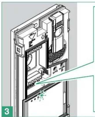

On the S1 DIP-switch, set the code corresponding to the function you want to program
| button 1 enabled with call address 1 (default) | buttons 1-2 enabled with call addresses 1-2 | buttons 1-2-3-4 enabled with call addresses 1-2-3-4 | Restore default |
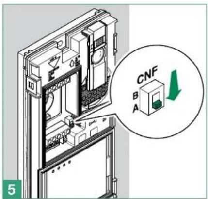

Reset the configuration of the DIP-switches of S1
TAB.AUsercode
| code | DIP switch ON | code | DIP switch ON | code | DIP switch ON | code | DIP switch ON | code | DIP switch ON | code | DIP switch ON | code | DIP switch ON | code | DIP switch ON |
| 1 1 31 1,2,3,4,5 61 | 1,3,4,5,6 | 91 1,2,4,5,7 12 | 1,4,5,6,7 151 1,2,3,5,8 | 181 1,3,5,6,8 211 1,2,5,7,8 | |||||||||||
| 2 2 3 6 62 2,3,4,5,6 | 92 3,4,5,7 122 2,4,5,6 | 7 152 4,5,8 182 2,3,5,6,8 212 3,5,7,8 | |||||||||||||
| 3 | 1,2 | 33 | 1,6 | 63 | 1,2,3,4,5,6 | 93 | 1,3,4,5,7 | 123 | 1,2,4,5,6,7 | 153 | 1,4,5,8 | 183 | 1,2,3,5,6,8 | 213 | 1,3,5,7,8 |
| 4 | 3 | 34 | 2,6 | 64 | 7 | 94 | 2,3,4,5,7 | 124 | 3,4,5,6,7 | 154 | 2,4,5,8 | 184 | 4,5,6,8 | 214 | 2,3,5,7,8 |
| 5 | 1,3 | 35 | 1,2,6 | 65 | 1,7 | 95 | 1,2,3,4,5,7 | 125 | 1,3,4,5,6,7 | 155 | 1,2,4,5,8 | 185 | 1,4,5,6,8 | 215 | 1,2,3,5,7,8 |
| 6 | 2,3 | 36 | 3,6 | 66 | 2,7 | 96 | 6,7 | 126 | 2,3,4,5,6,7 | 156 | 3,4,5,8 | 186 | 2,4,5,6,8 | 216 | 4,5,7,8 |
| 7 | 1,2,3 | 37 | 1,3,6 | 67 | 1,2,7 | 97 | 1,6,7 | 127 | 1,2,3,4,5,6,7 | 157 | 1,3,4,5,8 | 187 | 1,2,4,5,6,8 | 217 | 1,4,5,7,8 |
| 8 | 4 | 38 | 2,3,6 | 68 | 3,7 | 98 | 2,6,7 | 128 | 8 | 158 | 2,3,4,5,8 | 188 | 3,4,5,6,8 | 218 | 2,4,5,7,8 |
| 9 | 1,4 | 39 | 1,2,3,6 | 69 | 1,3,7 | 99 | 1,2,6,7 | 129 | 1,8 | 159 | 1,2,3,4,5,8 | 189 | 1,3,4,5,6,8 | 219 | 1,2,4,5,7,8 |
| 10 | 2,4 | 40 | 4,6 | 70 | 2,3,7 | 100 | 3,6,7 | 130 | 2,8 | 160 | 6,8 | 190 | 2,3,4,5,6,8 | 220 | 3,4,5,7,8 |
| 11 | 1,2,4 | 41 | 1,4,6 | 71 | 1,2,3,7 | 101 | 1,3,6,7 | 131 | 1,2,8 | 161 | 1,6,8 | 191 | 1,2,3,4,5,6,8 | 221 | 1,3,4,5,7,8 |
| 12 | 3,4 | 42 | 2,4,6 | 72 | 4,7 | 102 | 2,3,6,7 | 132 | 3,8 | 162 | 2,6,8 | 192 | 7,8 | 222 | 2,3,4,5,7,8 |
| 13 | 1,3,4 | 43 | 1,2,4,6 | 73 | 1,4,7 | 103 | 1,2,3,6,7 | 133 | 1,3,8 | 163 | 1,2,6,8 | 193 | 1,7,8 | 223 | 1,2,3,4,5,7,8 |
| 14 | 2,3,4 | 44 | 3,4,6 | 74 | 2,4,7 | 104 | 4,6,7 | 134 | 2,3,8 | 164 | 3,6,8 | 194 | 2,7,8 | 224 | 6,7,8 |
| 15 | 1,2,3,4 | 45 | 1,3,4,6 | 75 | 1,2,4,7 | 105 | 1,4,6,7 | 135 | 1,2,3,8 | 165 | 1,3,6,8 | 195 | 1,2,7,8 | 225 | 1,6,7,8 |
| 16 | 5 | 46 | 2,3,4,6 | 76 | 3,4,7 | 106 | 2,4,6,7 | 136 | 4,8 | 166 | 2,3,6,8 | 196 | 3,7,8 | 226 | 2,6,7,8 |
| 17 | 1,5 | 47 | 1,2,3,4,6 | 77 | 1,3,4,7 | 107 | 1,2,4,6,7 | 137 | 1,4,8 | 167 | 1,2,3,6,8 | 197 | 1,3,7,8 | 227 | 1,2,6,7,8 |
| 18 | 2,5 | 48 | 5,6 | 78 | 2,3,4,7 | 108 | 3,4,6,7 | 138 | 2,4,8 | 168 | 4,6,8 | 198 | 2,3,7,8 | 228 | 3,6,7,8 |
| 19 | 1,2,5 | 49 | 1,5,6 | 79 | 1,2,3,4,7 | 109 | 1,3,4,6,7 | 139 | 1,2,4,8 | 169 | 1,4,6,8 | 199 | 1,2,3,7,8 | 229 | 1,3,6,7,8 |
| 20 | 3,5 | 50 | 2,5,6 | 80 | 5,7 | 110 | 2,3,4,6,7 | 140 | 3,4,8 | 170 | 2,4,6,8 | 200 | 4,7,8 | 230 | 2,3,6,7,8 |
| 21 | 1,3,5 | 51 | 1,2,5,6 | 81 | 1,5,7 | 111 | 1,2,3,4,6,7 | 141 | 1,3,4,8 | 171 | 1,2,4,6,8 | 201 | 1,4,7,8 | 231 | 1,2,3,6,7,8 |
| 22 | 2,3,5 | 52 | 3,5,6 | 82 | 2,5,7 | 112 | 5,67 | 142 | 2,3,4,8 | 172 | 3,4,6,8 | 202 | 2,4,7,8 | 232 | 4,6,7,8 |
| 23 | 1,2,3,5 | 53 | 1,3,5,6 | 83 | 1,2,5,7 | 113 | 1,5,6,7 | 143 | 1,2,3,4,8 | 173 | 1,3,4,6,8 | 203 | 1,2,4,7,8 | 233 | 1,4,6,7,8 |
| 24 4 5 54 2,3,5,6 | 84 | 3,5,7 114 | 2,5,6,7 | 144 | 5,8 | 174 | 2,3,4,6,8 | 204 | 3,4,7,8 | 234 | 2,4,6,7,8 | ||||
| 25 | 1,4,5 | 55 | 1,2,3,5,6 | 85 | 1,3,5,7 | 115 | 1,2,5,6,7 | 145 | 1,5,8 | 175 | 1,2,3,4,6,8 | 205 | 1,3,4,7,8 | 235 | 1,2,4,6,7,8 |
| 26 | 2,4,5 | 56 | 4,5,6 | 86 | 2,3,5,7 | 116 | 3,5,6,7 | 146 | 2,5,8 | 176 | 5,6,8 | 206 | 2,3,4,7,8 | 236 | 3,4,6,7,8 |
| 27 | 1,2,4,5 | 57 | 1,4,5,6 | 87 | 1,2,3,5,7 | 117 | 1,3,5,6,7 | 147 | 1,2,5,8 | 177 | 1,5,6,8 | 207 | 1,2,3,4,7,8 | 237 | 1,3,4,6,7,8 |
| 28 | 3,4,5 | 58 | 2,4,5,6 | 88 | 4,5,7 | 118 | 2,3,5,6,7 | 148 | 3,5,8 | 178 | 2,5,6,8 | 208 | 5,7,8 | 238 | 2,3,4,6,7,8 |
| 29 | 1,3,4,5 | 59 | 1,2,4,5,6 | 89 | 1,4,5,7 | 119 | 1,2,3,5,6,7 | 149 | 1,3,5,8 | 179 | 1,2,5,6,8 | 209 | 1,5,7,8 | 239 | 1,2,3,4,6,7,8 |
| 30 | 2,3,4,5 | 60 | 3,4,5,6 | 90 | 2,4,5,7 | 120 | 4,5,6,7 | 150 | 2,3,5,8 | 180 | 3,5,6,8 | 210 | 2,5,7,8 | 240 | 5,6,7,8 |
4.7 ACTUATOR RELAY MODULE ART. 1256
Intelligent device for controlling a 24 AC/DC 10A relay (fitted) for general uses. Fit a max. of 10 actuator relay modules Art. 1256 on the whole system.
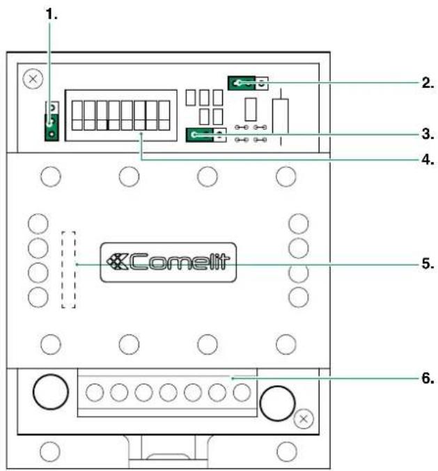
4.7.1 Parts description
1.JP4
2.JP3
3.JP2
To use the actuator relay module with kit HFX-7000M
Move jumper JP2 to position 2
Move jumper JP3 to position 2
Move jumper JP4 to position 2
- S1 DIP switch for different setting
- JP1 for functions setting
- Terminal block for system connection:
NC relay N.C. contact
COM relay COM contact
NO relay NO contact
LLBUS line input
+, - power supply input terminals
4.7.2 Functions
Art. 1256 offers the following functions, depending on the position of jumper JP1:
- External unit lighting control
- Activation function on Actuator pushbutton.
- Activation function on Actuator with code pushbutton
| JP1 | External unit lighting control The relay is operated by closing the C.NO. contact in response to a call from an external unit to any address, on internal ignition from a video entry phone (e.g. to automatically activate lights, CCTV alarm contacts, etc.). The relay closure time can be programmed using a S1 DIP-switch (see table A). |
| JP1 | Activation function on Actuator pushbutton The relay is operated by closing the C.NO. contact in response to a Generic actuator call from a video entry phone. The relay closure time can be programmed using a S1 DIP-switch (see table A). All Art. 1256 modules set for use with this function are activated simultaneously when the pushbutton on the internal unit is pressed. |
| Activation function on Actuator with code pushbutton The relay is operated by closing the C.NO. contact if the pushbutton pressed on the video entry phone has been programmed to send the actuator call with the code of the actuator. The closure time of the relay is fixed at 2 sec. To set the user code by means of a S1 DIP-switch, see “TAB. A User code” on page 30. |
| TAB. A: PROGRAMMING RELAY CLOSURE TIME (FOR EXTERNAL UNIT LIGHT FUNCTION/STAIR LIGHT FUNCTION, ACTIVATION FUNCTION ON ACTUATOR PUSHBUTTON) | |||||||||
| DIP switches sur ON | TOUS | 1 | 2 | 3 | 4 | 5 | 6 | 7 | 8 |
| Temps fermeture relais | * | 1" | 2" | 4" | 8" | 16" | 32" | 1' 5" | 2' 10" |
The relay for Art. 1256 operates in BISTABLE mode, changing its status at every command; if the power supply is cut off, it returns to the C.NO. position and remains there, even after the power is restored. Bistable mode is available for products with a revision index equal to or greater than 003.
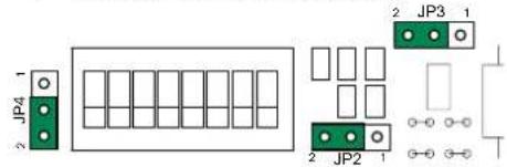
4.8 TV INTERFACE ART. 1257
Art. 1257 serves to extract an analogue video output from the system.
4.8.1 Parts description
- JP4 jumper for selecting Permanent or Timed mode of the OUT signal
- JP2 do not touch
- IND 1 DIP switch for settings
-
IND 2 DIP switch for settings
-
JP3 jumper for settings

To use the Art. 1257 with kit HFX-7000M: move jumper JP3 to position S2
- Terminal block for system connection:
\~+,- power supply input terminals
L L BUS line input
OUT GND 12V open collector output (max 30mA). Can be used for operating relays, triggering DVRs or as a "Function Switching" signal (switching input of the televisions)
V SH standard composite video signal
- CV5 video closure jumper
- JP1 do not touch
4.8.2 Functions
The module is capable of operating in different modes depending on the type of usage:
| Single address mode In this mode the Art. 1257 will be activated when a call is made to an internal unit with the same address. At least one addressed internal unit must be present, with the same address as set on the module. Art. 1257 will activate only after a call is made to that address. To programme this function, set the desired address (see page 30 "TAB. A User code") on DIP switch IND 1 and leave IND 2 at zero | Example setting code 7 IND 1 IND 2 | |
| ON 12345678 | ON 12345678 | |
| Independent Mode In this mode, the module must have a unique address (not used for other internal units). Art. 1257 will activate only after a call is made to that address. To programme this function, set IND 1 to "11111111" and set the desired address on IND 2 (see page 30 "TAB. A User code") | Example setting code 3 IND 1 IND 2 | |
| ON 12345678 | ON 12345678 | |
| Address range mode In this mode, at least one internal unit must be present for each address included in the range set on the module. Art. 1257 will activate only after a call is made to these addresses. To programme this function, set the minimum address in the range on DIP switch IND 1 and the maximum address in the range on IND 2 (see page 30 "TAB. A User code"). | Example setting MIN code 1 and MAX code 239 IND 1 IND 2 | |
| ON 12345678 | ON 12345678 | |
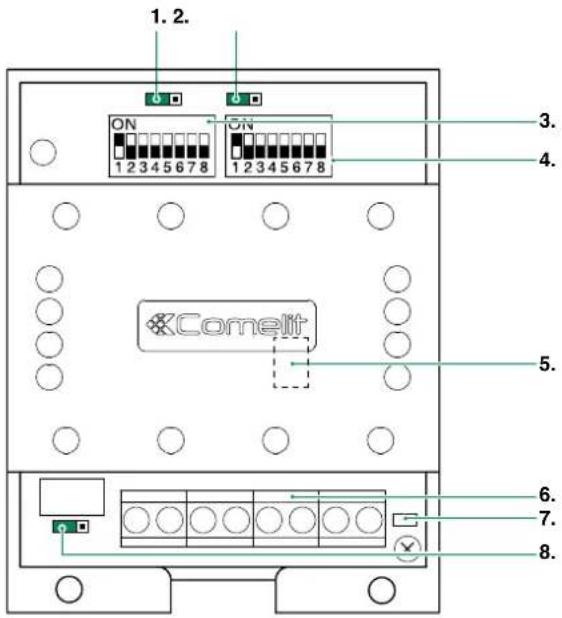
4.9 CCTV CAMERA INTERFACE ART. 1409
Art. 1409 allows to manage analog CCTV camera (up to 3).
4.9.1 Parts description
- Terminal block M2 for system connection:
INA not used
GND Common contact
V1 S1 Coax input camera 1
V2 S2 Coax input camera 2
V3 S3 Coax input camera 3
- TM2 Controls frequency of video signal modulation (factory-set to optimum setting: do not adjust)
- TM1 Controls amplitude of modulated video signal (factory-set to optimum setting: do not adjust)
- Programming micro-switches S1
- Terminal block M1 for system connection:
LOUT LOUT Bus line output
LIN LIN Bus line input
\~\~+Powerinput12Vac20Vdc
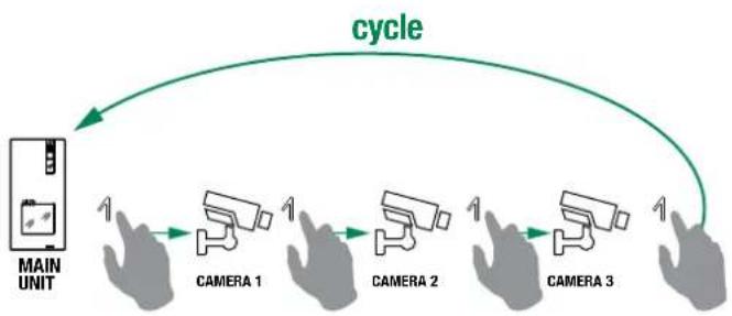
4.9.2 Operation
Monitor on
By pressing the programmed button, it is possible to toggle between the different cameras, according to the following diagram:

4.9.2.1 PROGRAMMING THE NUMBER OF CAMERAS CONNECTED
Select the number of cameras connected using switches 7 and 8 of selector S1, as shown in the following table.
| DIP 7 DIP 8 | |||
| 0 Cameras 0 0 | DP-SWITCHES 1 2 3 < 5 6 7 8 | ||
| 1 Camera 1 0 | DP-SWITCHES 1 2 3 4 5 6 7 8 | ||
| 2 Cameras 0 1 | DP-SWITCHES 1 2 3 4 5 6 7 8 | ||
| 3 Cameras 1 1 | DP-SWITCHES 1 2 3 4 5 6 7 8 |
4.9.2.2 FUNCTION 1: GENERIC ACTUATOR MODE
NOTE: Before programming the module, see the table: "4.9.2.4 Compatibility Table" on page 34.
By pressing the button programmed as "generic actuator", it is possible to toggle between the different cameras. Microswitch "S1" must be set as shown in following table
| DIP 1 DIP 2 DIP 3 DIP | 4 DIP 5 DIP 6 | ||||||
| Setting for generic actuator 1 1 0 0 | 0 0 | DIP-SMTCHES | |||||
4.9.2.3 FUNCTION 2: ACTUATOR WITH CODE MODE
NOTE: Before programming the module, see the table: "4.9.2.4 Compatibility Table" on page 34.
By pressing the button programmed as "coded actuator", it is possible to toggle between the different cameras. Microswitch "S1" must be set as shown in following table:
| Correspondence of 1409 address actuator with code on bracket | |||||||
| DIP1 | DIP2 | DIP3 | DIP4 | DIP5 | DIP6 | Address 1409 Actuator on bracket code | |
| 10 | 0000 | 0220 | |||||
| 10 | 1000 | 1221 | |||||
| 10 | 0100 | 2222 | |||||
| 10 | 1100 | 3223 | |||||
| 10 | 0010 | 4224 | |||||
| 10 | 1010 | 5225 | |||||
| 10 | 0110 | 6226 | |||||
| 10 | 1110 | 7227 | |||||
| DIP 1 DIP 2 | DIP 3 DIP | 4 | DIP 5 | DIP 6 | ||||
| Example of Address setting on Art.1409 for control using actuator code224. | 1000 | 10 | DIP-SWITCHES12345678 |
In this mode, with the video entry phone monitor switched on, by repeatedly pressing the actuator with code pushbutton, it is possible to cycle through ONLY the cameras connected to module 1409 with the corresponding address. In the same system, it is possible to install up to 8 1409 modules with different codes.
4.9.2.4 COMPATIBILITY TABLE
| COMPATIBILITY OF 1409 WITH 1256 OR OTHER 1409 | ||
| Generic actuator mode Actuator with code mode | ||
| Compatibility with 1256 | No 1256 in "Generic actuator mode" | No 1256 in "Actuator with code mode" with codes between 220 and 227 |
| Compatibility with 1409 | No other 1409 | Only 1409 in "Actuator with code mode" with different codes |
5. System function
5.1 PERFORMING CALLS
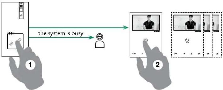
5.1.1 How to call from the external unit
To send the call from an external unit, touch the call pad corresponding to the user you want to contact.
On the external unit the camera LED will light up, the LED will flash and the confirmation tone will sound. The video image from the external unit will appear automatically on internal monitor/s.
If the system is busy: the LED will flash and the external unit will emit the system busy tone.
5.1.2 How to answer a call from an internal unit
"On receipt of a call from the external unit you will hear the call ringtone
Press to enter into communication with the caller LED will illuminate on the external unit.
Press again to terminate the call.
A call from the external unit always takes priority over an intercom communication or a paging call
the call in progress will be ended for the other devices.
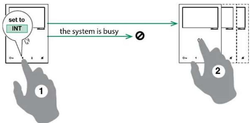
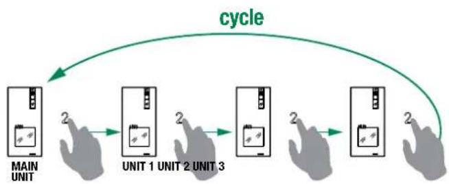
5.1.3 How to transmit a call to the other internal units
This function can be used to transmit a call to the other internal units set to the same user code or set to another user code (for programming see page 23 "4.2 Configuration Capacitivetouch keys Art. Ex-7000H").
Press the programmed button to send the call
If the system is busy: the LED will flash 4 times
5.1.4 How to answer a call from an internal unit
"On receipt of a call from the internal unit you will hear the call ringtone. With "privacy mode on" the internal unit will ring in any case.
Press to enter into communication with the caller
Press again to terminate the call.
A call from the external unit always takes priority over an intercom communication or a paging call.
5.2 PAGING CALL
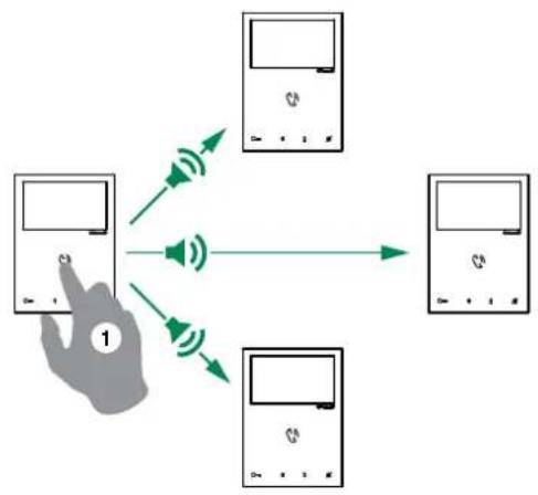
5.2.1 How to initiate a paging call
Pre to initiate the all-page chime
After the chime sounds, a 30 seconds message can be broadcast to all monitors on the system (maximum 4 monitors).
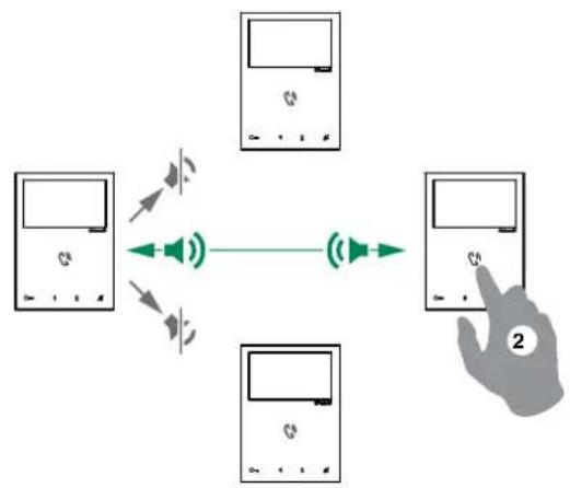
5.2.2 How to answer a paging call
Pre to answer the paging call
a (300 seconds) point to point conversation between the two monitor is established.
the paging call will be terminated for the other devices.

A call from the external unit always takes priority over an intercom communication or a paging call.
the call in progress will be terminated for the other devices.
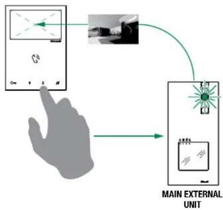
5.3 SELF-IGNITION FUNCTION
Self-ignition is possible only when the system is in standby
Press the self-ignition button (by default) to display on the monitor the video from the external unit.

Press again to cycle through several cameras.
If a call is underway with an external unit it is NOT possible to cycle between the external units
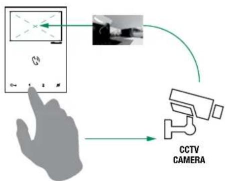
5.3.1 How to display on the monitor the image transmitted from the CCTV camera
During "call in progress" or during Self-ignition.
Press the programmed button to display on the monitor the image transmitted from the CCTV camera.
Press again to cycle through several cameras and come back to the external unit
5.4 LOCK RELEASE FUNCTION

During "call in progress" or during Self-ignition.
Press to release the lock.
"the LED will illuminate on the external unit.
5.5 ACTIVATION / DEACTIVATION PRIVACY MODE

Press to disable/enable the ringtone for calls from the external unit and paging call.
The red LED indicates that the Privacy function is active.

In privacy mode the paging call are still received
5.6 ACTIVATION / DEACTIVATION DOCTOR FUNCTION


3 Sec
Press the programmed button for 3 sec to disable/enable the doctor function ^ 念 3 flashes (every 5 sec.) of theLED indicate that the doctor function is active.
5.7 ACTIVATION / DEACTIVATION AUTOMATIC ANSWER MODE
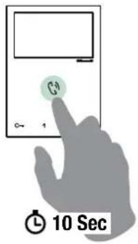
Pre for 10 sec to activate / deactivate automatic answer mode
A confirmation tone will sound
The LED indicates that the automatic answer mode is active.

Feature is not suitable when 2 or more monitors are installed
5.8 BRIGHTNESS CONTROL

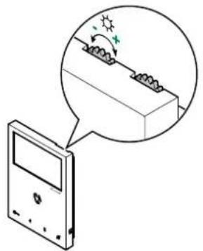
To increase the brightness, turn clockwise
5.9 LOUDSPEAKER VOLUME CONTROL
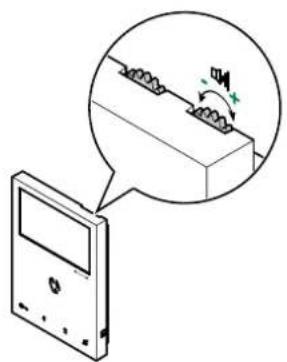
To increase the volume, turn clockwise
6. Technical specification
6.1 EX-7000H MAIN MONITOR
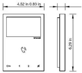
| Display | 4.3" Color LCD Screen |
| Resolution | 480x272pixel |
| Auto Timer (intercom) | $00sec |
| Operating Temperature | Class B1 normal range indoor 41° F /104° F (5°C / 40°C) |
| Dimensions (with bracket) | WxHxD 4.52x6.29x0.83 in (115x160x21.5 mm) |
| Power consumption | 10 W MAX |
6.2 EX-DSM EXTERNAL UNIT
| Image Sensor | 4" CMOS |
| Resolution | 600TVL - 640(H)*480(V) |
| Camera Lens | F2.1 |
| View Angle | 98° diagonal |
| Auto Light Sensor | NO |
| Operating Temperature | Class A2 wide range outdoor -13°F / 131°F (-25°C / + 55°C) |
| Dimensions (with bracket) WxHxD | 3.79×7.72×1.06 in (96.2×196.2×27 mm) |
| Power consumption | 8W MAX |
| Door release: (relay contact) | 24V DC 2A |
| Door release: (direct current output) | 1000uF-25V capacitive discharge - 12Vdc-200mA holding |
| Compatible locks | 12V AC, 12V DC |
6.3 1209/4 BUS POWER SUPPLY
| Power consumption | 12W MAX |
| Operating Temperature | Class A1 wide range indoor 23°F /104°F (-5°C +40°C) |
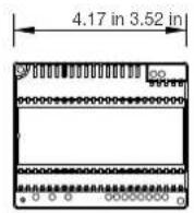
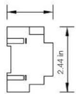
| Dimensions WxHxD | 4.17x3.52x2.44 in (106x89.5x62 mm) |
| CSA Rating | US and Canada |
6.4 ACTUATOR RELAY MODULE ART. 1256
| Power consumption 1.5W MAX |
| Operating Temperature 32° F / 86° F (0°C / 30°C) |
| Dimensions W×H×D 2.6×3.35×1.38 in (66×85×35 mm) |
6.5 TV INTERFACE ART. 1257
| Power consumption $W MAX |
| Operating Temperature 32°F / 86°F (0°C / 30°C) |
| Dimensions WxHxD 2.6×3.35×1.38 in (66×85×35 mm) |
6.6 REMOTE CAMERA MODULE ART. 1409
| Power consumption $W MAX |
| Operating Temperature 23°F/104°F (-5°C/+40°C) |
| Dimensions WxHxD 2.6x3.35x1.38 in (66x85x35 mm) |
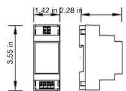
6.7 DOOR EXPANDER ART. 1405
| Power consumption 0,2W MAX |
| Operating Temperature 23° F/104°F (-5°C/+40°C) |
| Dimensions WxHxD 1.42x3.54x2.28 in (36x90x58 mm) |
7. Appendix
7.1 WARNING
WARNING:
TO REDUCE THE RISK OF FIRE OR ELECTRIC SHOCK, DO NOT EXPOSE THE MONITOR OR POWER ADAPTER TO WATER OR MOISTURE.
CAUTION:
DO NOT OPEN. RISK OF ELECTRICAL SHOCK.
CAUTION!
TO REDUCE RISK OF ELECTRICAL SHOCK, DO NOT REMOVE COVER OR BACK, NO USER SERVICEABLE PARTS INSIDE, REFER SERVICING TO QUALIFIED SERVICE PERSONNEL.
OTHERWARNINGS
Monitor is designed for indoor use only. Do not install outdoors.
- Keep the equipment dry. If water should get in, wipe off immediately. Water contains minerals that can erode electronic circuits.
- Intercom system is not operational during a power failure.
- Intercom system may be affected by radio frequency interference or EMI (electrical magnetic interference) in areas where broadcasting station antennas are close by.
- Keep all wiring at least 1 foot away from fluorescent lighting, dimmer switches and AC power.
EXPLANATION OF TWO SYMBOLS

The lighting flash with arrowhead symbol, within an equilateral triangle, is intended to alert the user to the presence of uninsulated "dangerous voltage" within the products enclosure that may be of sufficient magnitude to constitute risk of electrical shock to persons.

The exclamation point within an equilateral triangle is intended to alert the user to the presence of important operating and maintenance (servicing) instructions in the literature accompanying the appliance.
7.2 IMPORTANT SAFETY INSTRUCTIONS
WARNING:
TO REDUCE THE RISK OF FIRE OR ELECTRIC SHOCK, DO NOT EXPOSE THE MONITOR OR POWER ADAPTER TO WATER OR MOISTURE.
- Read Instructions -All the safety and operating instructions should be read before operating this equipment. These instructions should be retained for future reference.
Heed Warnings - All warnings on the equipment and in the operating instructions should be adhered to. All instructions regarding care and operation of this equipment should be followed. - Power Sources - Equipment should only be connected to the power supply specified in the operating instructions or as marked on the equipment.
Power Cord Protection - Keep cable cords and plugs clear off other objects, particularly at the point where they exit the equipment. - Cleaning - Clean the equipment by wiping with a soft cloth (do not use any abrasive agents or water).
Non-use Periods - Power cords should be unplugged from the outlet when left unused for a long period of time. - Object and Liquid Entry - Take care not to drop objects or liquids on any part of the equipment.
-
Damage Requiring Service -The unit should be serviced by a qualified service personnel when:
-
The power supply cord or the plug has been damaged or
- Objects have fallen, or liquid has been spilled onto the equipment or
The equipment has been exposed to rain or - The equipment does not appear to operate normally or exhibits a marked change in performance or
The equipment has been dropped and/or the enclosure has been damaged.
Servicing - Do not attempt to service the appliance beyond that described in the operating instructions. All other servicing should be referred to as Qualified Distributor's Service Personnel.
7.3 FCC CLASS B NOTICE
NOTE:
This equipment has been Certified and found to comply with the limits regulated by FCC. and CE. Therefore, it is designed to provide reasonable protection against interference and will not cause interference with other appliance usage. However, it is imperative that the user follows this manuals guidelines to avoid improper usage which may result in damage to the unit, electrical shock, and fire hazard or injury. In order to improve the feature functions and quality of the product, the specifications are subject to change without notice from time to time.
NOTE:
This equipment has been tested and found to comply with the limits for a Class B digital device, pursuant to Part 15 of the FCC rules. These limits are designed to provide reasonable protection against harmful interference in a residential installation. This equipment generates uses and can radiate radio frequency energy and, if not installed and used in accordance with the instructions, may cause harmful interference with radio communications. However, there is no guarantee that interference will not occur in a particular installation. If this equipment does cause harmful interference to radio or television ion reception, which can be determined by turning the equipment off and on, the user is encouraged to try to connect the interference by one or more of the following measures:
- Reorient or relocate the monitor unit
- Increase the separation between the monitor and camera
- Connect the equipment on a separate outlet
- Consult the dealer or an experienced radio or television technician
7.4 GENERAL PRODUCT WARRANTY:
For all Comelit Branded Products (excluding HFX 700, 720 and 900 products) 2 year manufacturer's warranty from dealer date of Purchase. Proof of purchase by the dealer in the form of an invoice is necessary for all returns.
RMA (RETURN) Policy:
- RMA's MUST BE called in, in order to maintain accuracy. Faxed or emailed RMA requests will not be accepted.
- Before Requesting an RMA Number, the installer must call into our Tech support line to verify the condition of the product and for trouble shooting purposes in order for Comelit to determine if an RMA needs to be issued.
- If technical support does seem that a return is needed, they will issue a trouble ticket number associated with the issue related to the defective product. Trouble tickets are needed for all distributors to receive a RMA number.
- All equipment must be returned as received from the manufacturer with all parts included. If all parts are not received, this may cause a delay in the processing of the RMA and possible return of the parts to the customer.
- Return freight is paid by the customer (non-reimbursable). Comelit will pay "Return to Customer" freight charges.
- Product "out of warranty" is subject to repair charges to be paid by the customer.
For all Comelit products (Comelit Kits and Multi-tenant parts, excluding the HFX series and related parts)
- New Replacements will be given on all returns of defective products. Credit is only given to distributors in special circumstances based on Comelit approval.
- For Distributors asking for Credit, the purchase invoice must be included in the return shipment.
- All RMA's must include the RMA form completely filled out.
- Units sent in without proper paperwork will incur delays in processing and will bereturned to the requester.
For RMA inquiries please contact:
Comelit USA RMA Department
Toll Free: (800) 692-9739 Option 2
Main office: (626) 930-0388 Option 2
tech@comelitusa.com
Sommaire
6. Specifications techniques 79
6.1 MONTEUR PRINCIPAL EX-7000H 79
6.2 POSTE EXTERIEUR EX-DSM 79
6.3 ALIMENTATION ELECTRIQUE 1209/4 BUS. 79
6.4 MODULE RELAIS ACTIONNEUR ART. 1256
6.5 INTERFACETVART.1257 79
6.6 MODULE CAMERA DEPORTEE ART. 1409
6.7 UNITE D'EXTENSION DE LA VIDEO À LA PORTE ART. 1405....79
7.Annexe. 80
7.1 AVERTISSEMENT 80
7.2 CONSIGNES DE SECURITE IMPORTANTES 80
7.3 AVIS SUR LE FCC CLASSE B 81
7.4 GARANTIE GÉNÉRIQUE SUR LE PRODUIT 81
| DIP 1 | DIP 2 | DIP 3 | DIP 4 |
| 0 | 1 | 0 | 0 |
| C= | P1 | P2 | ||
| PAG/ | C= | INT | AI |
VSH signal video composite standard
NE PAS OUVRIR. RISQUE D'LECTROCUTION.
ATTENTION:
POUR RÉDUIRE LE RISQUE D'ÉLECTROCUTION, NE RETIRER NI LE COUVERCLE NI LE PANNEAU ARRÊRÈE. AUCUNE PIECE INTERNE NE POT ÉTRÉ REPARÉE PAR L'UTILISATEUR. CONFIER LA RÉPARATION AU PERSONNEL TECHNIQUE QUALIFIÉ.
AUTRES AVERTISSEMENTS
2.1 UNIDAD EXTERNA EX-DSM

| DIP S2 | |||
| DIP 1 DIP 2 DIP 3 DIP 4 | |||
| 0 0 0 0 | |||
| 1 0 0 0 | NULL AI | ||
| 0 1 0 0 | INT AI | ||
| 1 1 0 0 | ACT NULL | ||
| 0 | 0 | 1 | 0 |
| 1 0 1 0 | |||
| 0 1 1 0 | |||
| 0 0 1 1 | PAG | PAG | |
| 1 0 1 1 | |||
| 0 | 1 | 1 | 1 |
| 1 1 1 1 | |||
| PROGRAMACION DE LAS TECLAS | ||||
| P1 P2 | ||||
| PAG / AI | ACT AI | |||
| ACT | ACT | ACT | ||
| D | INT ACT | |||
| INT | INT | |||
| NULL | NULL | |||
| PROG | ||||
valor predeterminado
LEYENDA
| DIP 1 | DIP 2 | DIP 3 | DIP 4 |
| 0 | 1 | 0 | 0 |
for set all the following function:
| C | C- | P1 | P2 | |
| PAG / C | C- | INT | AI |
4.2.3.3 CÓMOPROGRAMARLA FUNCION PAGING
4.2.3.5 CÓMOPROGRAMARLA FUNCIONDOCTOR
6.2 UNIDAD EXTERNA EX-DSM
6.5 INTERFAZ DETV ART. 1257
| Consumo | |
| Temperatura de funciona | 32 °F / 86 °F (0 °C / 30 °C) |
| Dimensiones AnxAIxPr | 2,6x3,35x1,38 pulg. (66x85x35 mm) |
6.6 MÓDULO DE CÁMARA SEPARADA ART. 1409
| Consumo | |
| Temperatura de funciona}=23 °F/104 °F (-5 °C/+40 °C) | |
| Dimensiones AnxAIxPr=2,6x3,35x1,38 pulg. (66x85x35 mm) |
Comelit USA RMA Department
Telefonogruito: (800) 692-9739 Opcion 2