
POWX2040 - Plane PowerPlus - Free user manual and instructions
Find the device manual for free POWX2040 PowerPlus in PDF.

| Product type | Jointer planer |
| Brand | PowerPlus |
| Model | POWX2040 |
| Power supply | 230-240 V ~50 Hz |
| Power | 1500 W |
| No-load speed | 9000 min⁻¹ |
| Maximum planing width | 204 mm |
| Planer table dimensions | 740 x 210 mm |
| Jointer table dimensions | 270 x 204 mm |
| Parallel guide dimensions | 535 x 105 mm |
| Parallel guide tilt | 0° to 45° |
| Cutting depth (planing) | 0-2 mm |
| Cutting depth (jointing) | 0-2.5 mm |
| Jointing height | 5 – 120 mm |
| Feed speed | 5 m/min |
| Net weight | 24 kg |
| Sound pressure level (LpA) | 93 dB(A) |
| Sound power level (LwA) | 106 dB(A) |
| Main functions | Planing and jointing of wood up to 204 mm width |
| Maintenance and cleaning | Regular cleaning of ventilation slots, replacement of carbon brushes (length <5 mm), checking belts and bearings every 10 hours |
| Safety | Overcurrent protection, NVR switch, cutterhead guard, tilting parallel guide, extraction nozzle with lock |
| Spare parts and repairability | Blades (ref. 210 x 22 x 1.8 mm), carbon brushes, drive belt; repair by qualified technician recommended |
| Warranty | 36 months from date of purchase |
Frequently Asked Questions - POWX2040 PowerPlus
User questions about POWX2040 PowerPlus
0 question about this device. Answer the ones you know or ask your own.
Ask a new question about this device
Download the instructions for your Plane in PDF format for free! Find your manual POWX2040 - PowerPlus and take your electronic device back in hand. On this page are published all the documents necessary for the use of your device. POWX2040 by PowerPlus.
USER MANUAL POWX2040 PowerPlus
natural_image
Yellow industrial machine with open lid and mechanical components (no visible text or symbols)
NL NEDERLANDS VERTAALDE VERSIE VAN DE ORIGINELE HANDLEIDING
FR FRANÇAIS TRADUCTION DU MODE D'EMPLOI D'ORIGINE
EN ENGLISH ORIGINAL INSTRUCTION MANUAL
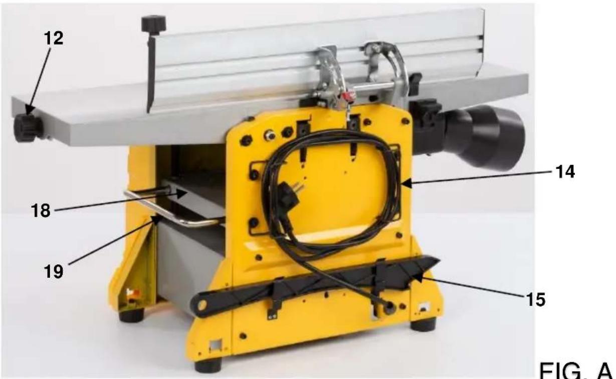
FIG. A

FIG. A

natural_image
Close-up of a yellow industrial machine with a hand holding a tool, labeled with number 11 (no text or symbols on the device itself)FIG. B
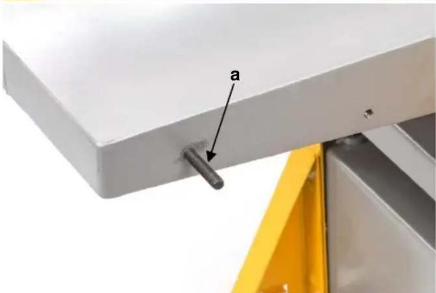
FIG. C

FIG. C

FIG. C

FIG. D
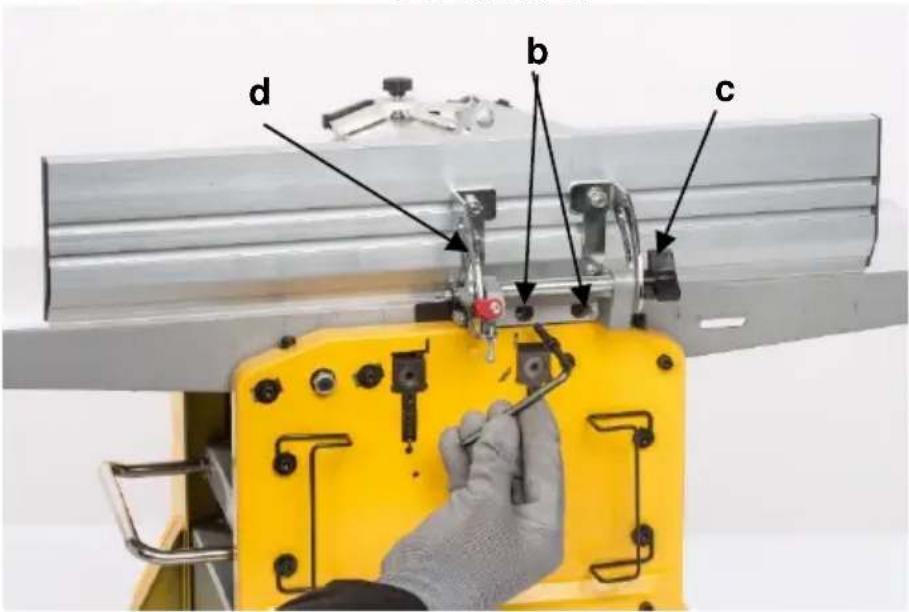
FIG. D

FIG. E

FIG. E

FIG. E

FIG. E
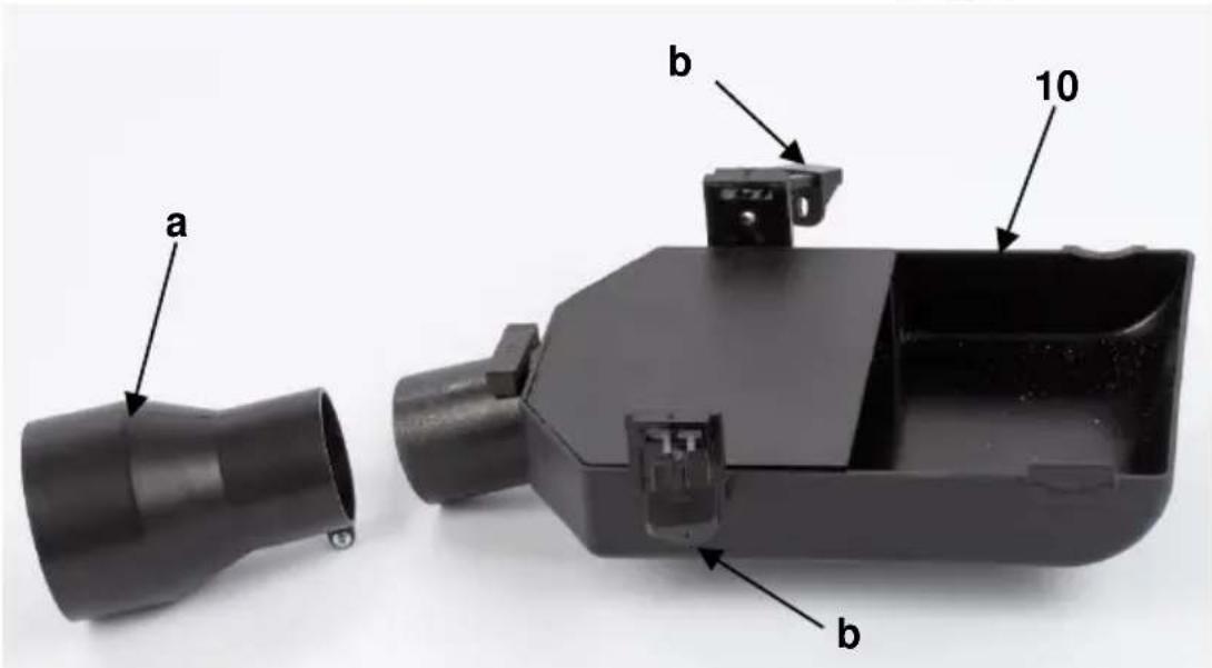
FIG. F
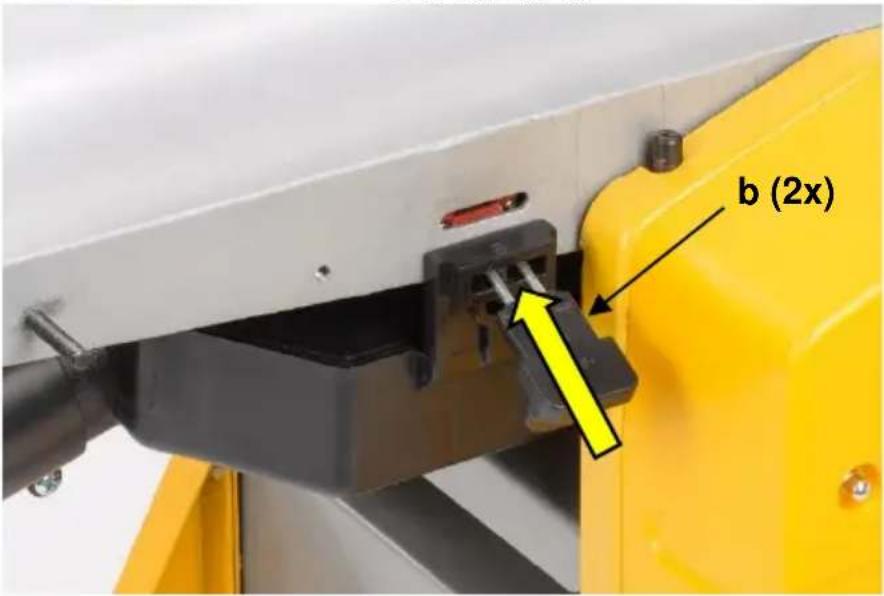
FIG. F
natural_image
Close-up of a mechanical device with black cylindrical component mounted on a yellow frame, no visible text or symbolsFIG. F
natural_image
Close-up of a black and silver mechanical device with a yellow base, no visible text or symbolsFIG. F
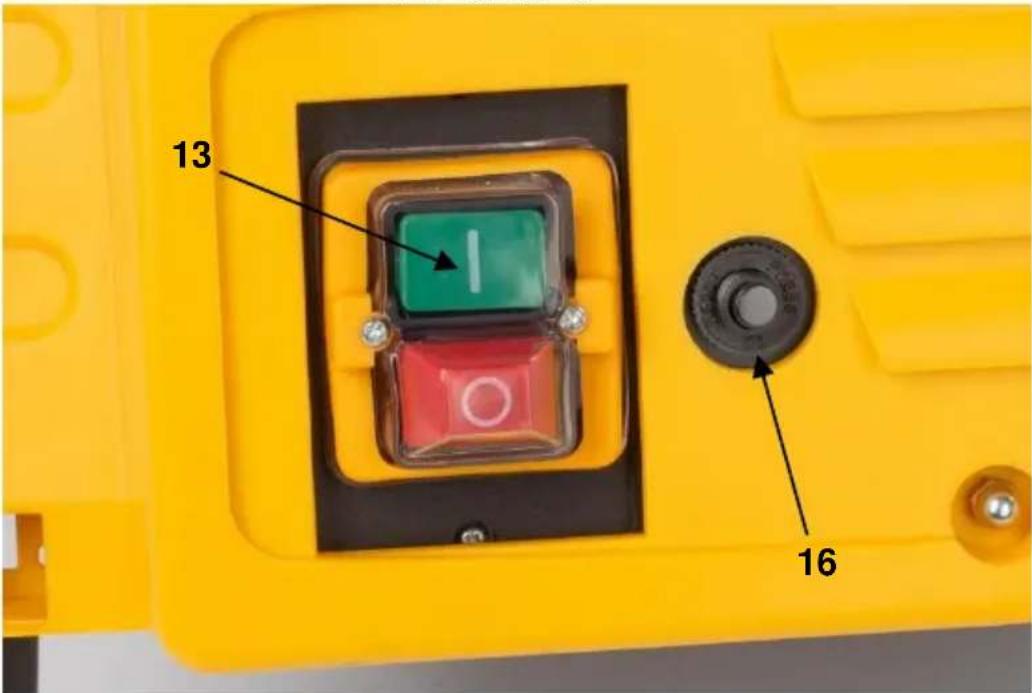
FIG. F

FIG. G
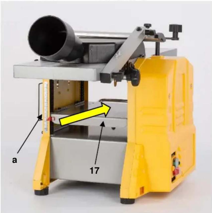
FIG. H

FIG. H
1 TOEPASSING 3
2 BESCHRIJVING (FIG. A) 3
3 INHOUD....3
4 TOELICHTING VAN DE SYMBOLEN 4
5 ALGEMENE VEILIGHEIDSVOORSCHRIFTEN ....4
5.1 Werkplaats....4
5.2 Elektrische veiligheid ....4
2 BESCHRIJVING (FIG. A)
15 PROBLEEMOPLOSSING
26/11/2021, Lier - Belgium
1 UTILISATION .... 3
2 DESCRIPTION (FIG. A) 3
3 LISTE DES PIÈCES CONTENUES DANS L'EMBALLAGE ...... 3
4 PICTOGRAMMES 4
5 CONSIGNES DE SÉCURITÉ GÉNÉRALES ....4
6 INSTRUCTIONS DE SÉCURITÉ ADDITIONNELLES......6
26/11/2021, Lier - Belgium
1 APPLICATION....3
2 DESCRIPTION (FIG A) 3
3 PACKAGE CONTENT LIST....3
4 SYMBOLS 4
5 GENERAL POWER TOOL SAFETY WARNINGS ....4
5.1 Work area 4
5.2 Electrical safety....4
5.3 Personal safety ....5
5.4 Power tool use and care....5
5.5 Service....6
6 SPECIFIC SAFETY WARNINGS....6
6.1 User....6
6.2 Blades : 6
6.3 Workpiece : 6
6.4 Machine:....6
6.5 Residual risks....6
7 ASSEMBLY 7
7.1 Placement of the appliance....7
7.2 Fitting the rubber feet (Fig. A & B)....7
7.3 Mounting the appliance on a solid surface 7
7.4 Installations of the cutter shaft cover (Fig. A & C)....7
7.5 Installations of the parallel guide (Fig. A & D)....7
7.6 Replacing and adjusting the cutting edges (FIG E)....7
7.7 Mounting the extraction hood (Fig. F) 8
8 BEFORE USING THE TOOL FOR THE FIRST TIME 9
8.1 Overcurrent protection (Fig. F) 9
9 OPERATION....9
9.1 Switching on.(Fig. A & F)....9
9.2 Planing function (Fig. A, D & G)....9
9.2.1 Set the angle of the parallel guide (7)....9
9.2.2 Set the Depth of Cut....9
9.2.3 Position the cutter shaft cover (4) so it covers any exposed part of the knives......9
9.3 Thicknessing function (Fig. A & H)....10
9.3.1 Use the thicknessing height lever (8) to adjust the height of the thicknessing table (17) to match the work piece....10
9.3.2 Move around to the other end of the machine to support the piece by hand as a second drive roller feeds it out of the machine....10
10 CLEANING AND MAINTENANCE....10
10.1 Cleaning....10
10.2 Lubrication....11
10.3 Regular checks (Fig. A) 11
10.4 Replacing the belt :....11
10.5 Replacing carbon brushes....11
11 TECHNICAL DATA....11
12 NOISE....12
13 SERVICE DEPARTMENT 12
14 STORAGE 12
15 TROUBLE SHOOTING 12
16 WARRANTY....13
17 ENVIRONMENT 13
18 DECLARATION OF CONFORMITY 14
JOINTER PLANER 204MM
POWX2040
1 APPLICATION
This jointer-planer can be used for all kinds of truing and finishing work in wood, e.g., facing, straightening, thinning, planing and jointing of natural wood up to 204mm in width.
It is not designed for commercial use.
Use this tool only for the type of work for which it has been designed.
Any use other then those indicated in this manual is a misuse.
In the event the user alone is responsible for damages or injuries stemming from such misuse.
The manufacturer shall not be held responsible for any modification made to the tool or for any damage that might result from said modifications.
Finally, use of this planer in accordance with the instructions in the present manual does not in itself guarantee the elimination of all residual risk factors.

WARNING! Read this manual and general safety instructions carefully before using the appliance, for your own safety. Your power tool should only be passed on together with these instructions.
2 DESCRIPTION (FIG A)
- Infeed table
- Outfeed table
- Cutter shaft
- Cutter shaft cover
- Cutter shaft cover locking knob
- Gear cover
- Parallel guide
- Thicknessing height lever
- Planing scale
-
Dust extraction hood
-
Rubber feet (4x)
- Planing depth knob
- Power switch
- Power cable storage
- Push stick storage
- Overcurrent protection reset button
- Thicknessing table infeed
- Thicknessing table outfeed
- Extendable support
3 PACKAGE CONTENT LIST
■ Remove all packing materials
■ Remove remaining packaging and transit supports (if existing)
- Check the completeness of the packing content
- Check the appliance, the power cord, the power plug and all accessories for transportation damages.
- Keep the packaging materials as far as possible till the end of the warranty period. Dispose it into your local waste disposal system afterwards.

WARNING Packing materials are no toys! Children must not play with plastic bags! Danger of suffocation!
1x planer thicknesser
1x parallel guide (+2x M5 bolts)
1x cutter shaft cover
1x cutter shaft cover arm (+ 1x screw & washer + 1x M6 bolt & wingnut)
1x cutter shaft cover wing nut
1x dust extraction hood
1x 100mm dust extraction adapter
2x push pad
1x push stick
4x rubber feet (+4x M8 bolts & washers)
1x cutter setting jig
1x thicknessing height lever
1x cutter shaft cover locking knob (+washer)
1x manual

When parts are missing or damaged, please contact your dealer.
4 SYMBOLS
In this manual and/or on the machine the following symbols are used:
 | Denotes risk of personal injury or damage to the tool. |  | Read manual before use |
 | Wear eye protection |  | Wear gloves |
 | In accordance with essential requirements of the European directive(s) | ||
5 GENERAL POWER TOOL SAFETY WARNINGS
Read all safety warnings and all instructions. Failure to follow all warnings and instructions may result in electric shock, fire and/or serious injury. Save all warnings and instructions for future reference. The term "power tool" in the warnings refers to your mains operated (corded) power tool or battery operated (cordless) power tool.
5.1 Work area
- Keep work area clean and well lit. Cluttered and dark areas invite accidents.
- Do not operate power tools in explosive atmospheres, such as in the presence of flammable liquids, gases or dust. Power tools create sparks which may ignite the dust or fumes.
- Keep children and bystanders away while operating a power tool. Distractions can cause you to lose control.
5.2 Electrical safety

Always check that the power supply corresponds to the voltage on the rating plate.
- Power tool plugs must match the outlet. Never modify the plug in any way. Do not use any adapter plugs with earthed (grounded) power tools. Unmodified plugs and matching outlets will reduce risk of electric shock.
- Avoid body contact with earthed or grounded surfaces such as pipes, radiators, ranges and refrigerators. There is an increased risk of electric shock if your body is earthed or grounded.
-
Do not expose power tools to rain or wet conditions. Water entering a power tool will increase the risk of electric shock.
-
Do not abuse the cord. Never use the cord for carrying, pulling or unplugging the power tool. Keep cord away from heat, oil, sharp edges or moving parts. Damaged or entangled cords increase the risk of electric shock.
- When operating a power tool outdoors, use an extension cord suitable for outdoor use. Use of a cord suitable for outdoor use reduces the risk of electric shock.
- If operating a power tool in a damp location is unavoidable, use a residual current device (RCD) protected supply. Use of an RCD reduces the risk of electric shock.
5.3 Personal safety
- Stay alert, watch what you are doing and use common sense when operating a power tool. Do not use a power tool while you are tired or under the influence of drugs, alcohol or medication. A moment of inattention while operating power tools may result in serious personal injury.
- Use safety equipment. Always wear eye protection. Safety equipment such as dust mask, non-skid safety shoes, hard hat, or hearing protection used whenever conditions require will reduce personal injuries.
- Avoid accidental starting. Ensure the switch is in the off position before plugging in. Carrying power tools with your finger on the switch or plugging in power tools that have the switch on invites accidents.
- Remove any adjusting key or wrench before turning the power tool on. A wrench or a key left attached to a rotating part of the power tool may result in personal injury.
- Do not overreach. Keep proper footing and balance at all times. This enables better control of the power tool in unexpected situations.
- Dress properly. Do not wear loose clothing or jewellery. Keep your hair, clothing and gloves away from moving parts. Loose clothes, jewellery or long hair can be caught in moving parts.
- If devices are provided for the connection of dust extraction and collection facilities, ensure these are connected and properly used. Use of these devices can reduce dust related hazards.
5.4 Power tool use and care
- Do not force the power tool. Use the correct power tool for your application. The correct power tool will do the job better and safer at the rate for which it was designed.
- Do not use the power tool if the switch does not turn it on and off. Any power tool that cannot be controlled with the switch is dangerous and must be repaired.
- Disconnect the plug from the power source before making any adjustments, changing accessories, or storing power tools. Such preventive safety measures reduce the risk of starting the power tool accidentally.
- Store idle power tools out of the reach of children and do not allow persons unfamiliar with the power tool or these instructions to operate the power tool. Power tools are dangerous in the hands of untrained users.
- Maintain power tools. Check for misalignment or sticking of moving parts, breakage of parts and any other condition that may affect the power tool's operation. If damaged, have the power tool repaired before use. Many accidents are caused by poorly maintained power tools.
- Keep cutting tools sharp and clean. Properly maintained cutting tools with sharp cutting edges are less likely to stick and are easier to control.
- Use the power tool, accessories and tool bits etc., in accordance with these instructions and in the manner intended for the particular type of power tool, taking into account the working conditions and the work to be performed. Use of the power tool for operations different from intended could lead to a hazardous situation.
5.5 Service
- Have your power tool serviced by a qualified repair person using only identical replacement parts. This will ensure that the safety of the power tool is maintained.
6 SPECIFIC SAFETY WARNINGS
DO NOT let familiarity with this product, gained from repeated use, replace strict adherence to planer safety rules. If you use this tool unsafely or incorrectly, you can suffer serious personal injury.
Always unplug your powertool before any repair, maintenance or when replacing the cutting blades.
6.1 User.
- Always stand aside when operating the machine. Never stand in front of the inlet / output opening of the planer.
■ Wear eye protection, also wear gloves
■ Always wear ear protection. - Do not wear ties, rings, bracelets, and jewelry which could get caught in moving parts during operation. Wear protective hair covering to contain long hair.
- Make sure that all covers are installed in place before operation.
6.2 Blades :
- Handle the blades very carefully.
- Use appropriate sharpened cutters adapted to the appliance
- Tighten the planer blade installation bolts securely before operation.
- Check the blades carefully for cracks or damage before operation. Replace cracked or damaged blades immediately.
- Every part of the unused cutters should be protected.
6.3 Workpiece :
- Remove nails and clean the workpiece before cutting! Nail, sand or foreign matter can cause blade damage or cause severe danger to the user.
6.4 Machine:
- Check before operation that the dust expel opening is not obstructed.
- Do not remove chips from the chip chute when the motor is running. Clean out chips after the blades come to a complete stop. Always use a stick etc. when cleaning them out.
- Do not leave the tool running. Wait until it has come to a complete stillstand.
■ Never plane more then 3 mm in one go.
■ To avoid risk of overheating or jamming, never force the tool. - Always fasten your machine to a workbench: before starting any work, check the stability of your machine..
6.5 Residual risks
■ These risks are present during operation, remain vigilant.
- Danger of injury to fingers or hands while changing the blade; wear gloves.
- Danger of injury caused by ejected debris; wear safety glasses.
■ Danger to hearing; wear safety ear muffs
- Risk of inhaling airborne particles; wear a dust protector mask.
Caution: sawdust and wood chips can cause allergies and injury. Fires and explosions can be triggered if oxygen from the air and a source of ignition are also present.
7 ASSEMBLY

Always disconnect the powertool from the mains before performing any maintenance.
7.1 Placement of the appliance
- If the appliance is used as a portable tool, mount it on a stable support so you can work safely without risk. Also make sure the rubber feet are properly mounted on the machine.
7.2 Fitting the rubber feet (Fig. A & B)
- Use the four M8x20mm bolts and washers with the hex key to attach the four rubber feet (11) to the underside of the body. (When mounting the appliance to a solid surface, the rubber feet do not need to be mounted)
7.3 Mounting the appliance on a solid surface
■ Before using the appliance, we recommend firmly anchoring its four feet to an underframe.
- The mounting surface must first be perforated.
- Each foot should be firmly bolted down with sufficiently long bolts (pay attention to the thickness of the work surface) and clamping washers (not provided); place the clamp nuts under the work surface.
- The size of the work surface should be sufficient to avoid upending the unit during the work.

ATTENTION: Before starting any job make sure the work surface is sufficiently stable and robust.
7.4 Installations of the cutter shaft cover (Fig. A & C)
■ Remove both bolt, washer and wingnut.
- Slide the cutter shaft cover (4) attachment in to the arm.
- Slide the M6 bolt through the hole at the end of the arm and simultaneously through the end of the bracket.
- Fit a washer over the bolt and then screw on the wing nut (b).
- Optionally also drive the screw and washer in the hole on top of the arm if needed.
- First mount the mounting bolt and then, slide the bottom of the arm over the mounting bolt (a) and fasten with the second wing nut (b).
- Screw in the cutter shaft cover locking knob (5).
7.5 Installations of the parallel guide (Fig. A & D)
- Locate the two tapped holes (a) on the side edge of the table.
- Insert two M5 x 20mm bolts (b) and washers thru the corresponding holes of the parallel guide mounting bracket and screw them in to the tapped holes.
- Check that your guide is stable and properly installed.
- Adjust the guide to your preference, it can be inclined to an angle of 45^ à 90^ .
- Lock in to position with the locking knob (c).
7.6 Replacing and adjusting the cutting edges (FIG E)
- Remove the parallel guide (7) for access to the cutters.
- Turn the cutter shaft (3) clockwise so that the spacer block and the cutter are visible (facing upward).
- Unscrew the 4 bolts (c) that hold the spacer block (b) using the 4mm hex key.
■ After unscrewing, remove the cutter (a) and its spacer block (b) - Clean each part carefully
-
Insert the spacer block with the cleaned cutters.
-
Align laterally so that no element protrudes to the right or left.
■ Make sure the 2 slots (e) in the cutter (a) sit onto the 2 cutter height setting screws (d). - Refit the spacer block (b) with the 4 bolts (c) screwed in but not tightened, the bolts (c) need to be slightly loose to make adjustment of the cutter (a) possible.
- Once installed you should make sure that the cutters are sitting properly in their sites. To do so, use the cutter setting jig (f) provided with the appliance.
- The cutter setting jig (f) should be placed on the outfeed table (2) with the lower edges (g) against the edge of the outfeed table.
- Adjust the position of the cutter (a) by turning the cutter shaft until the cutter (a) is centered between the in- and outfeed table (1) & (2).
- The cutter (a) must touch both bar curves (h) of the setting jig equally.
- Adjust the cutter position bolts (i) until the cutter sits correctly as described above.
- Re-tighten the 4 bolts (c) of the spacer block, and repeat above process for the second cutter.
- To install new cutters: proceed as above but use new cutters.

NOTE : Adjusting or replacing the cutters is a precise job ! The cutters must be set correctly and perfectly level and centered. Badly adjusted or replaced cutters will result in poorly finished surfaces and unstable performance which may result in personal injury ! We recommend having this job done by a qualified technician.

!! Handle the blades carefully to avoid risk of accidents. Do not touch the blades with your fingers.
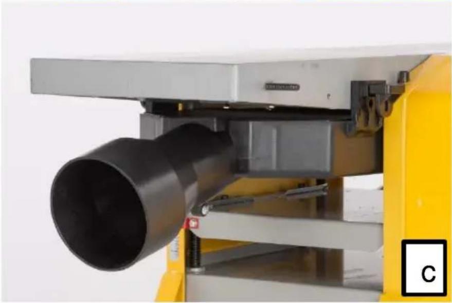
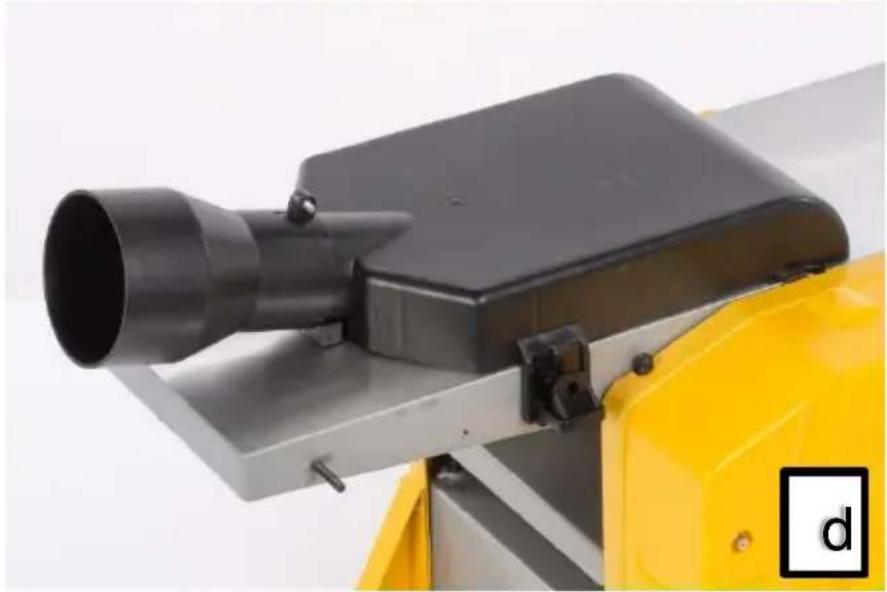
7.7 Mounting the extraction hood (Fig. F)

For a better dust extraction of the working surface, your machine can be connected to a vacuum cleaner. Attention: Dust particles can cause respiratory problems. For your protection, it is recommended that a standard anti-dust mask be used.

The machine is fitted with an interlocking safety switch and will not run without the dust extraction hood correctly fitted
The hood can be fitted in two different ways, depending on what type of operation is being carried out: Planing or Thicknessing The hood is locked in place using two locking latches which push into a receiver. One located on each side of the table.
Planing Operations
The dust extraction hood must be fitted underneath the outfeed table and locked in place using the two locking latches.
Thicknessing Operations
Remove the fence The extraction hood is then fixed on top of the outfeed table and locked in place using the two locking latches.
8 BEFORE USING THE TOOL FOR THE FIRST TIME
8.1 Overcurrent protection (Fig. F)
- This machine is equipped with an overcurrent protection that cuts power in the event of overload. If this occurs, wait 30 seconds and press the reset button.
- Then press the green "I" switch to restart.
9 OPERATION

Before the first start-up all covers and safety devices must be correctly installed.
9.1 Switching on.(Fig. A & F)
- Connect the machine to a 230V power source.
- To start the machine after settings and checks, use the on/off power switch.
- To start the machine, press the green "I" button; to stop the machine, press the red "O" button.
- Run the machine while empty for 30 seconds in a steady position to check that it is running well.
- Stop the machine immediately if there is a significant vibration or if other faults are noticed.
- If this happens, check the machine to determine the origin of the problem.
The machine is fitted with an NVR (No Voltage Release) switch.

This type of switch is designed so that if the machine is disconnected from the mains whilst running and then reconnected, the motor will not automatically restart.
9.2 Planing function (Fig. A, D & G)
9.2.1 Set the angle of the parallel guide (7).
- The guide fence can be set to any angle from 90 to 45 degrees. There are adjustable pre-set stops for those two positions.
- The guide fence is locked and unlocked by using the locking knob (c).
- Other angles can be set by reading off the scale (d).
9.2.2 Set the Depth of Cut
- Turn the knob (12), located on the end of the infeed table (1), clockwise to decrease the depth of cut.
- The planing scale (9) shows mm increments from 0 to 3. (Max. recommended is 2mm per pass)
- As a general rule, set the depth at 1mm and, if necessary, make 2 or 3 passes until the desired result is achieved.
9.2.3 Position the cutter shaft cover (4) so it covers any exposed part of the knives.
- Use the push pads (a) to hold the work piece firmly down against the table, feed the work piece across the knives, onto the out-feed table (2).
- When working with very thin material, set the cutter shaft cover (4) all the way across to the fence.
- Then set the height of the cutter shaft cover (4), so the work piece can pass underneath it.

When you use the appliance in planing mode :
ALWAYS use the 2 pushers to handle the workpiece safely (Fig Q).
9.3 Thicknessing function (Fig. A & H)
Standing with the power switch (13) side as the front the direction of feed is left to right.
9.3.1 Use the thicknessing height lever (8) to adjust the height of the thicknessing table (17) to match the work piece.
- The maximum depth of cut when thicknessing is 2mm. A feed height restrictor bar prevents a cut of more than 2mm being made.
- Standing in front of the machine, hold the work piece so it is flat against the thicknessing table (17) and gently push it to the right.
■ Release the work piece when you feel the drive roller take hold and feed it past the knives.
9.3.2 Move around to the other end of the machine to support the piece by hand as a second drive roller feeds it out of the machine.
- Repeat as many times as necessary to achieve the required dimensions of the piece.
- Each pass, rotate the thicknessing height lever (8) clockwise one turn to raise the bed by 2mm.
- The actual dimension can be read from the thickness scale (a).
- The out-feed end of the thicknessing table (18) has a extendable support (19) that can be extended to support the work piece as it emerges.

When you use the appliance in thicknessing mode :
- This machine is equipped with in feed rollers: the piece of wood will be automatically fed.
- To ensure smooth sliding, the in feed tables must be regularly lubricated.
- Avoid using wet wood.
- Regularly remove and clean away wood chips using caution.
- Avoid using pieces that are too small.
- Place the piece to be worked on the in feed table and progressively advance the piece to be worked.
- Warning! Advancing the piece too quickly generates burrs.
10 CLEANING AND MAINTENANCE

Attention !Before performing any work on the equipment, pull the power plug.
10.1 Cleaning
- Keep the ventilation slots of the machine clean to prevent overheating of the engine.
- Regularly clean the machine housing with a soft cloth, preferably after each use.
- Keep the ventilation slots free from dust and dirt.
- If the dirt does not come off use a soft cloth moistened with soapy water.

Never use solvents such as petrol, alcohol, ammonia water, etc. These solvents may damage the plastic parts.
10.2 Lubrication
■ The machine requires no additional lubrication.
10.3 Regular checks (Fig. A)
After about 10 hrs. of use we recommend checking or maintaining the following points:
■ First remove the gear cover (6) :
■ Movement of the in feed and out feed rollers, cleaning if necessary.
■ Movement of the pulley.
- Check the feed belts
- Check the tightness of the nuts, gears, chains, table adjustment of the planer.
- Check the carbon brushes
10.4 Replacing the belt :
- Remove the old belt and replace it with a new one, turning the belt gradually until it is firmly in place on each of the 2 pulleys.
10.5 Replacing carbon brushes
- Remove and check the carbon brushes regularly. Replace them when they have become shorter then 5mm. Keep the carbon brushes clean and free to slip in the holders. Both carbon brushes must be replaced at the same time. Only use original carbon brushes.
To replace :
Turn the appliance upside down and unscrew and remove the base. Remove the cover of the carbon port and replace the carbons. Then close the cover again and screw the base back on.

It is recommended to have parts replaced by a trained technician.
11 TECHNICAL DATA
| Voltage / frequency | 230-240V ~50Hz |
| Power input | 1500W |
| No load speed | 9000 min ^-1 |
| Cuts / min : | 18000 |
| Blade size : | 210 x 22 x 1,8mm (2pcs) |
| Planer table size : | 740 x 210mm |
| Thicknesser table size : | 270 x 204mm |
| Dimensions of parallel guide | 535 x 105 mm |
| Incline of parallel guide: | from 0° to 45° |
| Feeding speed : | 5m/min |
| Max planing width : | 204mm |
| Thicknesser height: | 5 - 120mm |
| Max depth : | |
| Jointer : | 0-2,5mm |
| Planer : | 0-2mm |
| Net weight : | 24 kg |
12 NOISE
Noise emission values measured according to relevant standard. (K=3)
Acoustic pressure level LpA 93 dB(A)
Acoustic power level LwA 106 dB(A)

ATTENTION! Wear hearing protection when sound pressure is over 85 dB(A).
13 SERVICE DEPARTMENT
- Damaged switches must be replaced by our after-sales service department.
- If the connecting cable (or mains plug) is damaged, it must be replaced by a particular connecting cable which is available from our service department. Replacement of the connecting cable must only be carried out by our service department (see last page) or by a qualified person (qualified electrician).
14 STORAGE
- Thoroughly clean the whole machine and its accessories.
- Store it out of the reach of children, in a stable and secure position, in a cool and dry place, avoid too high and too low temperatures.
- Protect it from exposure to direct sunlight. Keep it in the dark, if possible.
- Don't keep it in plastic bags to avoid humidity build-up.
15 TROUBLE SHOOTING
| PROBLEM | ACTION |
| The machine does not start | 1)Check that it is properly plugged into the outlet.2) Make sure that the chip extractor is correctly positioned |
| The machine stops itself | 1) Press the Reset button and wait several minutes.2) Check that the chip extraction ports are not obstructed. |
| The machine does not turn at full power | 1) Decrease the depth of the cut.2) Check the status of the blades.3) Check the carbon brushes4) Check the in feed belt located under the plastic gear cover. |
| The cuts are not clean | 1) Check the status of the blades2) Check the alignment of the blades.3) Plane the wood with the grain |
| The machine is not properly extracting the chips. | 1) Check that the extraction ports are not clogged |
16 WARRANTY
- This product is warranted for a 36-month period effective from the date of purchase by the first user.
- This warranty covers all material or production flaws excluding : batteries, chargers, defective parts subject to normal wear & tear such as bearings, brushes, cables, and plugs, or accessories such as drills, drill bits, saw blades, etc. ; damage or defects resulting from maltreatment, accidents or alterations; nor the cost of transportation.
- Damage and/or defects resulting from inappropriate use also do not fall under the warranty provisions.
- We also disclaim all liability for any bodily injury resulting from inappropriate use of the tool.
- Repairs may only be carried out by an authorised customer service centre for Powerplus tools.
- You can always obtain more information at the number 00 32 3 292 92 90.
- Any transportation costs shall always be borne by the customer, unless agreed otherwise in writing.
- At the same time, no claim can be made on the warranty if the damage of the device is the result of negligent maintenance or overload.
- Definitely excluded from the warranty is damage resulting from fluid permeation, excessive dust penetration, intentional damage (on purpose or by gross carelessness), inappropriate usage (use for purposes for which the device is not suitable), incompetent usage (e.g. not following the instructions given in the manual), inexpert assembly, lightning strike, erroneous net voltage. This list is not exhaustive.
- Acceptance of claims under warranty can never lead to the prolongation of the warranty period nor commencement of a new warranty period in case of a device replacement.
- Devices or parts which are replaced under the warranty therefore remain the property of Varo NV.
- We reserve the right to reject a claim whenever the purchase cannot be verified or when it is clear that the product has not been properly maintained. (Clean ventilation slots, carbon brushes serviced regularly, etc.).
- Your purchase receipt must be kept as proof of date of purchase.
- Your appliance must be returned undismantled to your dealer in an acceptably clean state, (in its original blow-moulded case if applicable to the unit), accompanied by proof of purchase.
17 ENVIRONMENT

Should your appliance need replacement after extended use, do not dispose of it with the household refuse, but in an environmentally safe way.
Waste produced by electrical machine items should not be handled like normal household rubbish. Please recycle where recycle facilities exist. Check with your Local Authority or retailer for recycling advice.
VARO N.V. - Vic. Van Rompuy N.V. - Joseph Van Instraat 9 - BE2500 Lier - BELGIUM, declares that,
product : Jointer Planer 204mm
trade mark : POWERplus
model : POWX2040
is in conformity with the essential requirements and other relevant provisions of the applicable European Directives, based on the application of European harmonized standards. Any unauthorized modification of the apparatus voids this declaration.
European Directives (including, if applicable, their amendments up to the date of signature);
2011/65/EU
2014/30/EU
2006/42/EC
European harmonized standards (including, if applicable, their amendments up to the date of signature);
EN61029-1:2009
EN61029-2-3:2011
EN IEC55014-1 : 2021
The undersigned acts on behalf of the company CEO,
Mertens Ludo
Ludo Mertens
Regulatory Affairs – Compliance Manager
26/11/2021, Lier - Belgium
1 EINSATZBEREICH .... 3
26/11/2021, Lier - Belgium
1 APLICACIÓN....3
26/11/2021, Lier - Belgium
1 APPLICAZIONE 3
Regulatory Affairs – Compliance Manager
26/11/2021, Lier - Belgium
1 APLICAÇÃO....3
26/11/2021, Lier - Belgium
1 BRUKSOMRÅDE 3
2 BESKRIVELSE (FIG. A) 3
3 PAKKENS INNHOLD 3
4 SYMBOLFORKLARING .... 4
5 GENERELLE SIKKERHETSFORSKRIFTER....4
26/11/2021, Lier - Belgium
1 ANVENDELSE 3
2 BESKRIVELSE (FIG. A) 3
3 MEDF∅LGENDE INDHOLD 3
4 SYMBOLER....4
5 GENERELLE SIKKERHEDSFORSKRIFTER ....4
26/11/2021, Lier - Belgium
26/11/2021, Lier - Belgium

natural_image
Yellow industrial machine with control panel and mechanical arms (no visible text or symbols)varo
WWW.VARO.COM
DESIGNED AND MARKETED BY VARO
©copyright by varo
VARO - VIC. VAN ROMPUY nv
JOSEPH VAN INSTRAAT 9 - 2500 LIER - BELGIUM
OFFICES:


- BESCHRIJVING (FIG. A)
- JOINTER PLANER 204MM
- POWX2040
- APPLICATION
- WARNING! Read this manual and general safety instructions carefully before using the appliance, for your own safety. Your power tool should only be passed on together with these instructions.
- DESCRIPTION (FIG A)
- PACKAGE CONTENT LIST
- WARNING Packing materials are no toys! Children must not play with plastic bags! Danger of suffocation!
- When parts are missing or damaged, please contact your dealer.
- SYMBOLS
- GENERAL POWER TOOL SAFETY WARNINGS
- Work area
- Electrical safety
- Always check that the power supply corresponds to the voltage on the rating plate.
- Personal safety
- Power tool use and care
- Service
- SPECIFIC SAFETY WARNINGS
- User.
- Blades :
- Workpiece :
- Machine:
- Residual risks
- ASSEMBLY
- Always disconnect the powertool from the mains before performing any maintenance.
- Placement of the appliance
- Fitting the rubber feet (Fig. A & B)
- Mounting the appliance on a solid surface
- ATTENTION: Before starting any job make sure the work surface is sufficiently stable and robust.
- Installations of the cutter shaft cover (Fig. A & C)
- Installations of the parallel guide (Fig. A & D)
- Replacing and adjusting the cutting edges (FIG E)
- Mounting the extraction hood (Fig. F)
- Planing Operations
- Thicknessing Operations
- BEFORE USING THE TOOL FOR THE FIRST TIME
- Overcurrent protection (Fig. F)
- OPERATION
- Before the first start-up all covers and safety devices must be correctly installed.
- Switching on.(Fig. A & F)
- The machine is fitted with an NVR (No Voltage Release) switch.
- This type of switch is designed so that if the machine is disconnected from the mains whilst running and then reconnected, the motor will not automatically restart.
- Planing function (Fig. A, D & G)
- Set the angle of the parallel guide (7).
- Set the Depth of Cut
- Position the cutter shaft cover (4) so it covers any exposed part of the knives.
- Thicknessing function (Fig. A & H)
- When you use the appliance in thicknessing mode :
- CLEANING AND MAINTENANCE
- Attention !Before performing any work on the equipment, pull the power plug.
- Cleaning
- Never use solvents such as petrol, alcohol, ammonia water, etc. These solvents may damage the plastic parts.
- Lubrication
- Regular checks (Fig. A)
- Replacing the belt :
- Replacing carbon brushes
- To replace :
- NOISE
- SERVICE DEPARTMENT
- STORAGE
- WARRANTY
- ENVIRONMENT
Brand : PowerPlus
Model : POWX2040
Category : Plane