
POWDP4050 - Plane PowerPlus - Free user manual and instructions
Find the device manual for free POWDP4050 PowerPlus in PDF.

| Product type | Cordless planer |
| Brand | PowerPlus |
| Model | POWDP4050 |
| Power supply | 20 V Li-ion battery (not included) |
| Motor type | Brushless |
| No-load speed | 14 000 min⁻¹ |
| Planing width | 82 mm |
| Max. planing depth | 2 mm |
| Max. rebate depth | 8 mm |
| Compatible battery | PowerPlus 20 V (type not included) |
| Compatible charger | PowerPlus 20 V (not included) |
| Battery capacity indicator | 3 LEDs (full, 60%, nearly depleted) |
| Sound pressure level LpA | 83 dB(A) |
| Sound power level LwA | 94 dB(A) |
| Vibration (aw) | 4,8 m/s² (K=1,5 m/s²) |
| Cutting width | 82 mm |
| Number of blades | 2 (replaceable) |
| Included accessories | Dust bag, depth guide, side guide, tightening key, hex key, instruction manual |
| Functions | Planing, rebating, chamfering |
| Dust extraction | Connection for external vacuum or dust bag |
| Warranty | 36 months |
| Weight | Approx. 3.2 kg (with battery) |
Frequently Asked Questions - POWDP4050 PowerPlus
User questions about POWDP4050 PowerPlus
0 question about this device. Answer the ones you know or ask your own.
Ask a new question about this device
Download the instructions for your Plane in PDF format for free! Find your manual POWDP4050 - PowerPlus and take your electronic device back in hand. On this page are published all the documents necessary for the use of your device. POWDP4050 by PowerPlus.
USER MANUAL POWDP4050 PowerPlus

NL NEDERLANDS VERTAALDE VERSIE VAN DE ORIGINELE HANDLEIDING
FR FRANÇAIS TRADUCTION DU MODE D'EMPLOI D'ORIGINE
EN ENGLISH ORIGINAL INSTRUCTION MANUAL
natural_image
Illustration of a hand using a ruler to measure a mechanical component (no text or symbols visible)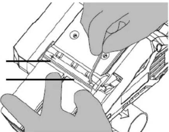
natural_image
Technical line drawing of hands installing or adjusting a mechanical component (no text or symbols visible)Fig 3 Fig. 4
Fig 3

natural_image
Technical line drawing of a mechanical device with a rotating knob and housing (no text or symbols)Fig. 5
natural_image
Technical line drawing of a mechanical device with no visible text or symbolsFig. 6
natural_image
Technical line drawing of a mechanical device with gears and actuators (no text or symbols)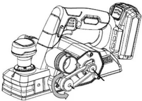
natural_image
Technical line drawing of a mechanical device with gears and housing (no text or symbols)Fig 7a Fig. 7b
natural_image
Mechanical assembly diagram showing gear and lock mechanism (no text or labels)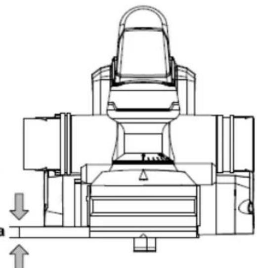
natural_image
Technical line drawing of a mechanical assembly with no visible text or symbolsFig 8a Fig. 8b
natural_image
Technical line drawing of a mechanical assembly with a close-up view showing a hand adjusting a component (no text or symbols present)Fig. 9
POWDP4050 NL
1 TOEPASSING .... 3
2 BESCHRIJVING (FIG. A)....3
3 INHOUD VAN DE VERPAKKING....3
4 TOELICHTING VAN DE SYMBOLEN 4
5 ALGEMENE VEILIGHEIDSVOORSCHRIFTEN ....4
5.1 Werkplaats....4
5.2 Elektrische veiligheid ....4
5.3 Veiligheid van personen....5
5.4 Zorgvuldige omgang met en gebruik van elektrisch gereedschap....5
5.5 Service....6
6 BIJZONDERE VEILIGHEIDSVOORSCHRIFTEN ....6
7 BIJKOMENDE VEILIGHEIDSINSTRUCTIES VOOR BATTERIJEN EN LADERS 6
7.1 Batterijen....6
7.2 Laders....7
8 OPLADEN EN INBRENGEN OF VERWIJDEREN VAN DE BATTERIJ ....7
8.1 Aanwijzingen op de lader....7
8.2 Verwijderen/inbrengen van de batterij....8
8.3 Indicator batterijcapaciteit....8
9 ASSEMBLAGE....8
9.1 De messen verwijderen (Fig. 1 & 2) 8
9.2 De messen monteren (Fig. 3 & 4)....8
9.3 De schaafdiepte instellen (Fig. 5)....9
9.4 De parallelgeleider monteren en instellen....9
10 GEBRUIK 9
10.1 In- en uitschakelen (Fig. 6)....9
10.2 Vervangen van de aandrijfriem (Fig. 7a, 7b)....9
10.3 Schaven....9
10.4 Sponningen maken (Fig. 8a & 8b)....9
10.5 Hoeken afschuinen (Fig. 9)....10
POWERPLUS HIGH QUALITY TOOLS
POWDP4050 NL
10.6 Stofafzuiging....10
11 REINIGING EN ONDERHOUD 10
11.1 Reiniging 10
12 TECHNISCHE GEGEVENS 10
13 GELUID 11
14 SERVICEDIENST....11
15 OPSLAG....11
16 GARANTIE 12
17 MILIEU....12
18 CONFORMITEITSVERKLARING .... 13
SCHAAFMACHINE 20 V POWDP4050
1 TOEPASSING
2 BESCHRIJVING (FIG. A)
04/03/2021, Lier - Belgium
04/03/2021, Lier - Belgium
1 APPLICATION....3
2 DESCRIPTION (FIG. A) 3
3 PACKAGE CONTENT LIST....3
4 SYMBOLS 4
5 GENERAL POWER TOOL SAFETY WARNINGS .... 4
5.1 Work area 4
5.2 Electrical safety....4
5.3 Personal safety .... 5
5.4 Power tool use and care....5
5.5 Service....6
6 ADDITIONAL SAFETY WARNINGS FOR PLANERS ...... 6
7 ADDITIONAL SAFETY INSTRUCTIONS FOR BATTERIES AND CHARGERS ....6
7.1 Batteries 6
7.2 Chargers....7
8 CHARGING AND INSERTION OR REMOVAL OF BATTERY .....7
8.1 Charger indications ....7
8.2 Removal / insertion of battery 7
8.3 Battery capacity indicator....7
9 ADJUSTMENTS/SETTINGS....8
9.1 Remove the blades (Fig. 1 & 2)....8
9.2 Install the blades (Fig. 3 & 4)....8
9.3 Setting the planing depth (Fig. 5)....8
9.4 Mounting and setting the parallel guide (Fig. 4)....8
10 OPERATION....8
10.1 Switching on and off (Fig. 6)....8
10.2 Drive belt replacement (Fig. 7a, 7b)....8
10.3 Planing....9
10.4 Rebating (Fig. 8a & 8b)....9
10.5 Edge chamfering (Fig. 9)....9
10.6 Dust extraction....9
POWERPLUS HIGH QUALITY TOOLS
POWDP4050 EN
11 CLEANING AND MAINTENANCE....9
11.1 Cleaning....10
12 TECHNICAL DATA....10
13 NOISE....10
14 SERVICE DEPARTMENT....10
15 STORAGE....10
16 WARRANTY....11
17 ENVIRONMENT....11
18 DECLARATION OF CONFORMITY 12
PLANER 20V POWDP4050
1 APPLICATION
Your planer has been designed for planing wooden workpieces. This tool is not suitable fur stationary use. It is not designed for professional use.

Warning! Read this manual and general safety instructions carefully before using the appliance, for your own safety. Your power tool should only be passed on together with these instructions.
2 DESCRIPTION (FIG. A)
- Scale
- Adjustment knob cutting depth
- Dust extraction outlet
- On/Off switch trigger
- Lock-off button
- Soft grip
- Belt cover
- Wing screw
- Spanner
- Planer base front
- V-shaped groove
- Parallel guide assembly
- Clamping screw
- Blade assembly
- Spring-loaded protective cover
- Planer base, rear
- Auto-retracting foot
- L Depth guide
- Storage for wrench and key
- Battery pack (NOT INCLUDED)
- Battery pack release button
- Charger (NOT INCLUDED)
- Battery capacity indicator
- Button for battery capacity indicator
3 PACKAGE CONTENT LIST
■ Remove all packing materials
■ Remove remaining packaging and transit supports (if existing)
- Check the completeness of the packing content
- Check the appliance, the power cord, the power plug and all accessories for transportation damages.
- Keep the packaging materials as far as possible till the end of the warranty period. Dispose it into your local waste disposal system afterwards.

WARNING Packing materials are no toys! Children must not play with plastic bags! Danger of suffocation!
1 planer
1 instruction manual
1 dust bag
1 side guide
1 wrench
1 hex key
1 depth guide

When parts are missing or damaged, please contact your dealer.
4 SYMBOLS
In this manual and/or on the machine the following symbols are used:
 | Denotes risk of personal injury or damage to the tool. |  | Read manual before use |
 | Mandatory use of eye protection. |  | Wear gloves |
 | "Class II - The machine is double insulated; Earthing wire is therefore not necessary (only for charger) |  | In accordance with essential requirements of the European directive(s). |
 | Do not expose charger and battery pack to water |  | Do not incinerate battery pack or charger |
 | Ambient temperature 40°C max. (only for battery) |  | Use battery and charger only in closed rooms |
5 GENERAL POWER TOOL SAFETY WARNINGS
Read all safety warnings and all instructions. Failure to follow all warnings and instructions may result in electric shock, fire and/or serious injury. Save all warnings and instructions for future reference. The term "power tool" in the warnings refers to your mains operated (corded) power tool or battery operated (cordless) power tool.
5.1 Work area
- Keep work area clean and well lit. Cluttered and dark areas invite accidents.
- Do not operate power tools in explosive atmospheres, such as in the presence of flammable liquids, gases or dust. Power tools create sparks which may ignite the dust or fumes.
- Keep children and bystanders away while operating a power tool. Distractions can cause you to lose control.
5.2 Electrical safety

Always check that the power supply corresponds to the voltage on the rating plate.
- Power tool plugs must match the outlet. Never modify the plug in any way. Do not use any adapter plugs with earthed (grounded) power tools. Unmodified plugs and matching outlets will reduce risk of electric shock.
- Avoid body contact with earthed or grounded surfaces such as pipes, radiators, ranges and refrigerators. There is an increased risk of electric shock if your body is earthed or grounded.
- Do not expose power tools to rain or wet conditions. Water entering a power tool will increase the risk of electric shock.
- Do not abuse the cord. Never use the cord for carrying, pulling or unplugging the power tool. Keep cord away from heat, oil, sharp edges or moving parts. Damaged or entangled cords increase the risk of electric shock.
POWDP4050 EN
- When operating a power tool outdoors, use an extension cord suitable for outdoor use. Use of a cord suitable for outdoor use reduces the risk of electric shock.
- If operating a power tool in a damp location is unavoidable, use a residual current device (RCD) protected supply. Use of an RCD reduces the risk of electric shock.
5.3 Personal safety
- Stay alert, watch what you are doing and use common sense when operating a power tool. Do not use a power tool while you are tired or under the influence of drugs, alcohol or medication. A moment of inattention while operating power tools may result in serious personal injury.
- Use safety equipment. Always wear eye protection. Safety equipment such as dust mask, non-skid safety shoes, hard hat, or hearing protection used whenever conditions require will reduce personal injuries.
- Avoid accidental starting. Ensure the switch is in the off position before plugging in. Carrying power tools with your finger on the switch or plugging in power tools that have the switch on invites accidents.
- Remove any adjusting key or wrench before turning the power tool on. A wrench or a key left attached to a rotating part of the power tool may result in personal injury.
- Do not overreach. Keep proper footing and balance at all times. This enables better control of the power tool in unexpected situations.
- Dress properly. Do not wear loose clothing or jewellery. Keep your hair, clothing and gloves away from moving parts. Loose clothes, jewellery or long hair can be caught in moving parts.
- If devices are provided for the connection of dust extraction and collection facilities, ensure these are connected and properly used. Use of these devices can reduce dust related hazards.
5.4 Power tool use and care
- Do not force the power tool. Use the correct power tool for your application. The correct power tool will do the job better and safer at the rate for which it was designed.
- Do not use the power tool if the switch does not turn it on and off. Any power tool that cannot be controlled with the switch is dangerous and must be repaired.
- Disconnect the plug from the power source before making any adjustments, changing accessories, or storing power tools. Such preventive safety measures reduce the risk of starting the power tool accidentally.
- Store idle power tools out of the reach of children and do not allow persons unfamiliar with the power tool or these instructions to operate the power tool. Power tools are dangerous in the hands of untrained users.
- Maintain power tools. Check for misalignment or sticking of moving parts, breakage of parts and any other condition that may affect the power tool's operation. If damaged, have the power tool repaired before use. Many accidents are caused by poorly maintained power tools.
- Keep cutting tools sharp and clean. Properly maintained cutting tools with sharp cutting edges are less likely to stick and are easier to control.
- Use the power tool, accessories and tool bits etc., in accordance with these instructions and in the manner intended for the particular type of power tool, taking into account the working conditions and the work to be performed. Use of the power tool for operations different from intended could lead to a hazardous situation.
POWDP4050 EN
5.5 Service
- Have your power tool serviced by a qualified repair person using only identical replacement parts. This will ensure that the safety of the power tool is maintained.
6 ADDITIONAL SAFETY WARNINGS FOR PLANERS
■ Before using the tool, make sure that the cutters have been properly mounted.
- Do not use the tool before It has been fully adjusted according to the Instructions.
■ Before planing, let the tool run without load to check if the cutters are properly balanced.
- Never load the tool so much that the motor is coming 10 a standstill,
- When planing, shavings may assemble in the grooves. Do not remove the shavings with your hands - use a piece of wood,
- Only use the cutter cylinder and cutters supplied with the tool.
- Use original accessories only.
- Only use sharp cutters.
- If you want to make adjustments to the tool, switch it off, wait for the cylinder to come to a standstill and unplug the tool,
- Switch off the tool and wait for the cutters to come to a standstill before putting the tool down. Reduce the planing depth to avoid contact between the cutters and other objects.
7 ADDITIONAL SAFETY INSTRUCTIONS FOR BATTERIES AND CHARGERS

Use only batteries and chargers applicable for this machine.
7.1 Batteries
■ Never attempt to open for any reason.
- Do not store in locations where the temperature may exceed 40 °C.
- Charge only at ambient temperatures between 4 °C and 40 °C.
- Store your batteries in a cool dry place (5 °C-20 °C). Never store batteries in discharged state.
It is better for Li-ion batteries to discharge and reload them regularly (at least 4 times a year). The ideal charge for long-term storage of your Li-ion battery is 40% of capacity.
- When disposing of batteries, follow the instructions given in the section "Protecting the environment".
- Do not cause short circuits. If connection is made between the positive (+) and negative (-) terminal directly or via accidental contact with metallic objects, the battery is short circuited and an intense current will flow causing heat generation which may lead to casing rupture or fire.
- Do not heat. If batteries are heated to above 100 °C, sealing and insulating separators and other polymer components may be damaged resulting in electrolyte leakage and/or internal short circuiting leading to heat generation causing rupture or file. Moreover do not dispose of the batteries in fire, explosion and/or intense burning may result.
- Under extreme conditions, battery leakage may occur. When you notice liquid on the battery, proceed as follows:
- Carefully wipe the liquid off using a cloth. Avoid skin contact.
– In case of skin or eye contact, follow the instructions below:
√ Immediately rinse with water. Neutralize with a mild acid such as lemon juice or vinegar.
√ In case of eye contact, rinse abundantly with clean water for at least 10 minutes. Consult a physician.
Fire hazard! Avoid short-circuiting the contacts of a detached battery. Do not incinerate the battery.
7.2 Chargers
- Never attempt to charge non-rechargeable batteries.
- Have defective cords replaced immediately.
- Do not expose to water.
- Do not open the charger.
- Do not probe the charger.
■ The charger is intended for indoor use only.
8 CHARGING AND INSERTION OR REMOVAL OF BATTERY
8.1 Charger indications
Connect the charger to the power outlet socket
- Solid green: ready to charge
■ Flickering red: charging - Solid green: charged
■ Solid green en red: battery or charger damaged

Note: if the battery does not fit properly, disconnect it and confirm that the battery pack is the correct model for this charger as shown on the specification chart. Do not charge any other battery pack or any battery pack that does not securely fit the charger.
- Frequently monitor the charger and battery pack while connected
- Unplug the charger and disconnect it from the battery pack when finished.
- Allow the battery pack to cool completely before using it.
- Store the charger and battery pack indoors, out of reach of children.

NOTE: If battery is hot after continuous use in the tool, allow it to cool down to room temperature before charging. This will extend the life of your batteries.
8.2 Removal / insertion of battery

WARNING: Before making any adjustments ensure the tool is switched off or remove the battery pack.
- Hold the tool with one hand and the battery pack (20) with the other.
- To install: push and slide battery pack into battery port, make sure the release latch on the rear side of the battery snaps into place and battery is secure before beginning operation.
- To remove: Press the battery release latch and pull the battery pack out at the same time.
8.3 Battery capacity indicator
There are battery capacity indicators (23) on the battery pack, you can check the capacity status of the battery if you squeeze the button (24). Before using the machine, please press switch trigger to check if the battery is full enough for properly working.
Those 3 LED might show the status of the capacity level of the battery:
■ 3 LED's are litt: Battery fully charged
■ 2 LED's are litt: Battery 60% charged
■ 1 LED is litt: Battery almost discharged
9 ADJUSTMENTS/SETTINGS
9.1 Remove the blades (Fig. 1 & 2)

Always put on gloves when replacing blades!
- Place the tool on a table with the base plate pointing towards you.
- Loosen the 3 installation bolts 1/2 rotation anticlockwise with the panner provided.
- Press and hold the spring-loaded protective cover, and slide the blade out of its holder with use of the tip of a spanner/screwdriver.

If one of the blades is damaged, always replace both blades.
9.2 Install the blades (Fig. 3 & 4)
- First clean out all chips or foreign material adhering to the drum(a) or blades(b)
■ Always replace blades with same dimension and weight. - Slide the blade into the blade holder. The blade must be level with the planer's base plate. The blade must be positioned exactly in the middle of the blade holder.
- Tighten the 3 installation bolts.

Always unplug the tool before replacing the cutters.
9.3 Setting the planing depth (Fig. 5)
- Plane depth is variable from 0 to 2.0 ~mm . This is adjustable by rotating the adjustment knob of cutting depth (2).
- As the knob is rotated clockwise from the "0" position the cutting depth will increase from 0 to as much as 2.0 mm.
- It is recommended that test cuts are made in scrap wood after each re-adjustment to make sure the desired amount of wood is being removed by the planer.
■ Several shallow passes will produce a smoother finish than one deep pass.
9.4 Mounting and setting the parallel guide
The parallel guide assembly is for use when you wish to plane parallel to the work piece.
- Secure the parallel guide holder to the left-hand side or right-hand side of the planer using the wing screw.
- Now secure the parallel stop guide rail "T" to the holder using the wing screw and the knob. The guide rail must always point downwards.
- Set the required distance between the guide rail and the work piece.
- Tighten the knob on the guide rail.
10 OPERATION
10.1 Switching on and off (Fig. 6)
■ Before engaging the on/off switch, check the blades are fitted properly.
- To switch on the planer, press the lock-off button (5) and push the ON/OFF switch trigger (4).
- When you release the ON/OFF switch trigger, the machine turns off.
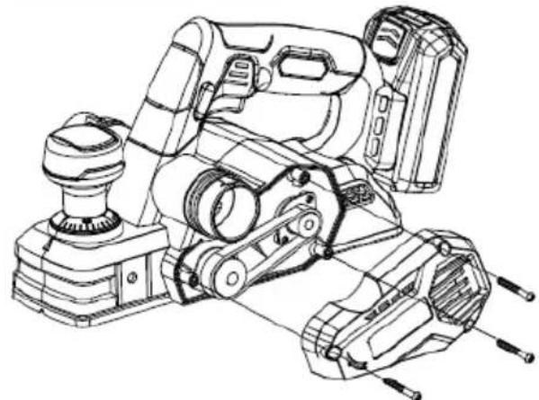
10.2 Drive belt replacement (Fig. 7a, 7b)
- Remove the belt cover (7) by unscrewing the 3 installation bolts.
- Wear gloves, turn the driven pulley by one hand slowly and pull the belt out by another hand until the belt fallsl out of the pulley.
- To install the belt proceed in reverse order.
10.3 Planing
- Choose the desired cutting depth before operation.
- Hold the planer with one hand on the switch and the other hand on the adjustment knob (2).
- Place planer's shoe on the surface to be planed. Making certain that the cutting blades are not touching the surface.
- Push down firmly on the adjustment knob of the planer. So that the planer's base is completely flat on the work piece surface. Depress the lock-off button and push the trigger switch. Allow the motor to reach full speed before starting to plane.
- Move the tool slowly over the work piece and maintain downward pressure to keep the planer flat. Be particularly careful to keep the tool flat at the beginning and the end of the work piece surface.
- ATTENTION: Never change the cutting depth while operating, to not create any irregularities on the planed surface.
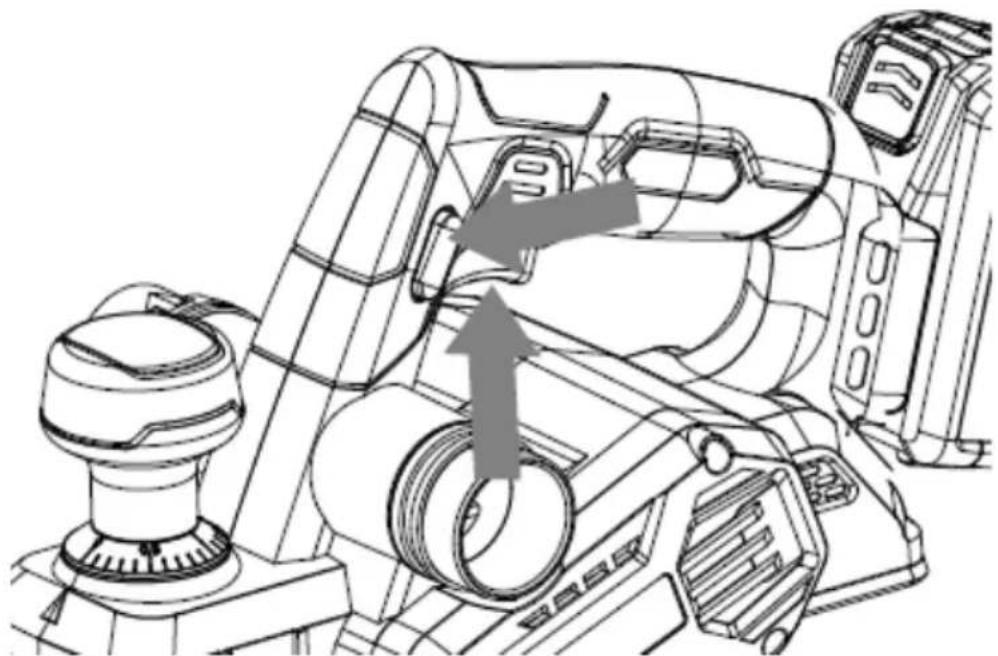
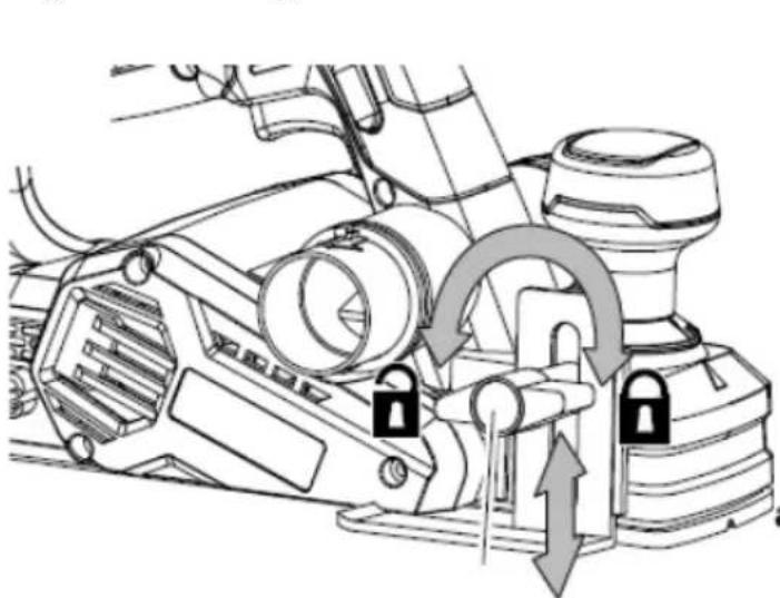
10.4 Rebating (Fig. 8a & 8b)
- Insert the screw provided through the slot on the rebate. Turn the screw into the nut on the housing.
■ The cut depth adjustment can be set from 0 to 8 mm - To adjust the depth of cut, place the planer on a flat board, then loosen the screw and slide the cut depth adjustment guide up and down for required depth.
- Tighten the thumb screw fully.
The depth of rebating cut is determines by moving the rebate and the number of passes made along the workpiece. Make sure that the planer is guided with a lateral supporting pressure.
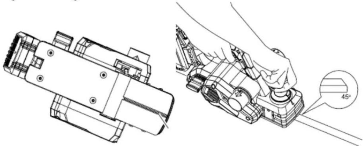
10.5 Edge chamfering (Fig. 9)

Always use both hands on the tool for any operation. It assures to maintain control and avoid risk of serious personal injury. The workpiece must always be properly supported and clamped so that both hands will be free to control the planer.
- Using the V-groove is the base plate you can make a chamfer on the work piece edge.
- Guide the planer along the edge and maintain a constant angle and force to produce a good finish.
- You can control the angle of the chamfer with your hands.
■ Make a test chamfer on a scrap piece of wood. - Maintain downward pressure to keep your planer flat at the beginning and the end of the work surface.
10.6 Dust extraction
- When using the planer dust will be generated.
■ Always use the dust bag supplied with your product. - The dust extraction outlet can be connected to an external vacuum cleaner to extract while operating.
11 CLEANING AND MAINTENANCE

Attention !Before performing any work on the equipment, pull the power plug.
11.1 Cleaning
- Keep the ventilation slots of the machine clean to prevent overheating of the engine.
- Regularly clean the machine housing with a soft cloth, preferably after each use.
- Keep the ventilation slots free from dust and dirt.
- If the dirt does not come off use a soft cloth moistened with soapy water.

Never use solvents such as petrol, alcohol, ammonia water, etc. These solvents may damage the plastic parts.
12 TECHNICAL DATA
| Voltage | 40V |
| Engine type | Brushless |
| No load speed | 14.000 rpm |
| Planing width | 82 mm |
| Max Planing depth | 2 mm |
13 NOISE
Noise values measured according to relevant standard. (K=3)
| Acoustic pressure level LpA | 83 dB(A) |
| Acoustic power level LwA | 94 dB(A) |

ATTENTION! The sound power level may exceed 85 dB(A), in this case individual hearing protection shall be worn.
aw (Vibration)
4.8 m/s²
K = 1.5 ~m / s^2
14 SERVICE DEPARTMENT
- Damaged switches must be replaced by our after-sales service department.
- If the connecting cable (or mains plug) is damaged, it must be replaced by a special connecting cable which is available from our service department. Replacement of the connecting cable should only be carried out by our service department (see last page) or by a specialist (qualified electrician).
15 STORAGE
- Thoroughly clean the whole machine and its accessories.
- Store it out of the reach of children, in a stable and secure position, in a cool and dry place, avoid too high and too low temperatures.
- Protect it from exposure to direct sunlight. Keep it in the dark, if possible.
- Don't keep it in plastic bags to avoid humidity build-up.
16 WARRANTY
- This product is warranted for a 36-month period effective from the date of purchase by the first user.
- This warranty covers all material or production flaws excluding : batteries, chargers, defective parts subject to normal wear & tear such as bearings, brushes, cables, and plugs, or accessories such as drills, drill bits, saw blades, etc. ; damage or defects resulting from maltreatment, accidents or alterations; nor the cost of transportation.
- Damage and/or defects resulting from inappropriate use also do not fall under the warranty provisions.
- We also disclaim all liability for any bodily injury resulting from inappropriate use of the tool.
- Repairs may only be carried out by an authorised customer service centre for Powerplus tools.
- You can always obtain more information at the number 00 32 3 292 92 90.
- Any transportation costs shall always be borne by the customer, unless agreed otherwise in writing.
- At the same time, no claim can be made on the warranty if the damage of the device is the result of negligent maintenance or overload.
- Definitely excluded from the warranty is damage resulting from fluid permeation, excessive dust penetration, intentional damage (on purpose or by gross carelessness), inappropriate usage (use for purposes for which the device is not suitable), incompetent usage (e.g. not following the instructions given in the manual), inexpert assembly, lightning strike, erroneous net voltage. This list is not exhaustive.
- Acceptance of claims under warranty can never lead to the prolongation of the warranty period nor commencement of a new warranty period in case of a device replacement.
■ Devices or parts which are replaced under the warranty therefore remain the property of Varo NV
- We reserve the right to reject a claim whenever the purchase cannot be verified or when it is clear that the product has not been properly maintained. (Clean ventilation slots, carbon brushes serviced regularly, etc.).
- Your purchase receipt must be kept as proof of date of purchase.
- Your appliance must be returned undismantled to your dealer in an acceptably clean state, (in its original blow-moulded case if applicable to the unit), accompanied by proof of purchase.
17 ENVIRONMENT

Should your appliance need replacement after extended use, do not discard it with the household rubbish but dispose of it in an environmentally safe way. Waste produced by electrical machine items should not be handled like normal household rubbish. Please recycle where recycle facilities exist. Check with your Local Authority or retailer for recycling advice.
18 DECLARATION OF CONFORMITY


VARO N.V. - Vic. Van Rompuy N.V. Joseph Van Instraat 9 - BE2500 Lier - BELGIUM, declares that,
Product: Planer
Trade mark: POWERplus
Model: POWDP4050
is in conformity with the essential requirements and other relevant provisions of the applicable European Directives, based on the application of European harmonized standards. Any unauthorized modification of the apparatus voids this declaration.
European Directives (including, if applicable, their amendments up to the date of signature);
2011/65/EU
2006/42/EC
2014/30/EU
European harmonized standards (including, if applicable, their amendments up to the date of signature);
EN62841-1:2015
EN62841-2-14:2015
EN55014-1:2017
EN55014-2:2015
EN61000-3-2:2014
EN61000-3-3:2013
Keeper of the Technical Documentation : Philippe Vankerkhove, VARO – Vic. Van Rompuy N.V.
The undersigned acts on behalf of the company CEO,
Mertens Ludo
Ludo Mertens
Regulatory Affairs – Compliance Manager
04/03/2021, Lier - Belgium
1 x Schraubenschlüssel
04/03/2021, Lier - Belgium
04/03/2021, Lier - Belgium
Regulatory Affairs – Compliance Manager
04/03/2021, Lier - Belgium
9.1 Remover as lâminas (Fig. 1 & 2)
9.2 Instalar as lâminas (Fig. 3 & 4)
04/03/2021, Lier - Belgium
1 BRUKSOMRÅDE 3
2 BESKRIVELSE (FIG. A) 3
3 PAKKENS INNHOLD .... 3
4 SYMBOLFORKLARING .... 4
5 GENERELLE SIKKERHETSADVARSLER 4
5.1 Arbeidsplassen 4
5.2 Elektrisk sikkerhet 4
5.3 Personsikkerhet....5
5.4 Vær nøyaktig og omhyggelig når du omgås elektroverktøy 5
5.5 Service....6
6 UTFYLLENDE SIKKERHETSFORSKRIFTER FOR ELEKTRISKE H∅VLER....6
7 EKSTRA SIKKERHETSREGLER FOR BATTERIER OG LADERE.
6
7.1 Batterier....6
7.2 Ladere....7
8 LADING OG INNSETTING ELLER FJERNING AV BATTERIET ...7
8.1 Laderindikasjoner....7
8.2 Fjerning/innsetting av batteri 7
8.3 Batterikapasitetsindikator....7
9 MONTASJE / JUSTERINGER 8
9.1 Fjerne kniven (Fig. 1 & 2)....8
9.2 Installere kniven (Fig. 3 & 4)....8
9.3 Stille inn høveldybde (Fig. 5)....8
9.4 Montere og justere parallellanslaget....8
10 BRUK....8
10.1 Slå på og av (Fig. 6)....8
10.2 Skifte av drivreim (Fig. 7a, 7b)....8
10.3 Høvling....9
10.4 Falsing (Fig. 8a & 8b)....9
10.5 Kantavfasing (Fig. 9)....9
POWERPLUS HIGH QUALITY TOOLS
POWDP4050 NO
10.6 Støvavsug....9
11 TEKNISKE DATA....9
12 ST∅Y 10
13 SERVICEAVDELING....10
14 OPPBEVARING .... 10
15 GARANTI....10
16 MILJ∅ 11
17 SAMSVARSERKLÆRING....11
1 BRUKSOMRÅDE
04/03/2021, Lier - Belgium
1 ANVENDELSE ....3
2 BESKRIVELSE (FIG. A) 3
3 MEDF∅LGENDE INDHOLD 3
4 SYMBOLER....4
5 ALMINDELIGE SIKKERHEDSANVISNINGER FOR EL-VÆRKT∅J 4
3 FÖRPACKNINGSINNEHÅLL
04/03/2021, Lier - Belgium
04/03/2021, Lier - Belgium
POWDP4050 HR
1 PRIMJENA ....3
2 OPIS (SLIKA A)....3
3 POPIS SADRŽAJA PAKETA 3
4 SIMBOLI 4
5 OPĆA UPOZORENJA O SIGURNOSTI RUKOVANJA
ELEKTRIČNIM ALATIMA......4
5.1 Radno mjesto....4
5.2 Električna sigurnost....4
5.3 Osobna sigurnost .... 5
5.4 Uporaba i održavanje električnog alata ....5
5.5 Servis....6
6 POSEBNA SIGURNOSNA UPOZORENJA 6
7 DODATNE SIGURNOSNE UPUTE ZA BATERIJE I PUNJAČE ....6
7.1 Baterije 6
7.2 Punjači....7
8 PUNJENJE I UMETANJE ILI UKLANJANJE BATERIJE....7
8.1 Indikatori punjača 7
8.2 Uklanjanje / umetanje baterije....7
8.3 Indikator kapaciteta baterije....7
9 PRILAGODBE/PODEŠAVANJA 8
9.1 Skinite noževe (slika 1 i 2)....8
9.2 Stavite noževe (slika 3 i 4)....8
9.3 Podešavanje dubine blanjanja (slika 5)....8
9.4 Postavljanje i podešavanje paralelne vodilice 8
10 RAD 8
10.1 Uključivanje i isključivanje (slika 6)....8
10.2 Zamjena pogonskog remena (slike 7a, 7b)....9
10.3 Blanjanje....9
10.4 Blanjanje rubnog utora (slika 8a i 8b)....9
10.5 Obrada rubova (slika 9)....9
10.6 Odvod prašine....9
POWERPLUS® HIGH QUALITY TOOLS
POWDP4050 HR
11 ČIŠĆENJE I ODRŽAVANJE 10
11.1 Čišćenje....10
12 TEHNIČKI PODACI....10
13 BUKA....10
14 SERVIS....10
15 SKLADIŠTENJE....10
16 JAMSTVO....11
17 OKOLIŠ 11
18 IZJAVA O SUKLADNOSTI 12
BLANJALICA 20 V POWDP4050
1 PRIMJENA
04/03/2021, Lier - Belgium
04/03/2021, Lier - Belgium
04/03/2021, Lier - Belgium
04/03/2021, Lier - Belgium
04/03/2021, Lier - Belgium

natural_image
Orange PowerPlus electric drill with black handle and control panel (no visible text or symbols)DISCOVER THE ENTIRE PRODUCT RANGE AT
WWW.DUAL-POWER.COM


- POWDP4050 NL
- POWERPLUS HIGH QUALITY TOOLS
- SCHAAFMACHINE 20 V POWDP4050
- TOEPASSING
- BESCHRIJVING (FIG. A)
- POWDP4050 EN
- PLANER 20V POWDP4050
- APPLICATION
- DESCRIPTION (FIG. A)
- PACKAGE CONTENT LIST
- SYMBOLS
- GENERAL POWER TOOL SAFETY WARNINGS
- Work area
- Electrical safety
- Personal safety
- Power tool use and care
- Service
- ADDITIONAL SAFETY WARNINGS FOR PLANERS
- ADDITIONAL SAFETY INSTRUCTIONS FOR BATTERIES AND CHARGERS
- Batteries
- Chargers
- CHARGING AND INSERTION OR REMOVAL OF BATTERY
- Charger indications
- Removal / insertion of battery
- Battery capacity indicator
- ADJUSTMENTS/SETTINGS
- Remove the blades (Fig. 1 & 2)
- Always put on gloves when replacing blades!
- If one of the blades is damaged, always replace both blades.
- Install the blades (Fig. 3 & 4)
- Always unplug the tool before replacing the cutters.
- Setting the planing depth (Fig. 5)
- Mounting and setting the parallel guide
- OPERATION
- Switching on and off (Fig. 6)
- Drive belt replacement (Fig. 7a, 7b)
- Planing
- Rebating (Fig. 8a & 8b)
- Edge chamfering (Fig. 9)
- Dust extraction
- CLEANING AND MAINTENANCE
- Cleaning
- NOISE
- SERVICE DEPARTMENT
- STORAGE
- WARRANTY
- ENVIRONMENT
- DECLARATION OF CONFORMITY
- Remover as lâminas (Fig. 1 & 2)
- Instalar as lâminas (Fig. 3 & 4)
- POWDP4050 NO
- BRUKSOMRÅDE
- FÖRPACKNINGSINNEHÅLL
- POWDP4050 HR
- POWERPLUS® HIGH QUALITY TOOLS
- BLANJALICA 20 V POWDP4050
- PRIMJENA
Brand : PowerPlus
Model : POWDP4050
Category : Plane