PowerConnect 3524P - Switch DELL - Free user manual and instructions
Find the device manual for free PowerConnect 3524P DELL in PDF.
| Product Type | Managed PoE Network Switch |
| Brand | Dell |
| Model | PowerConnect 3524P |
| Power Supply | 100-240 V AC, 50-60 Hz |
| Number of Ports | 24 PoE 10/100/1000 Ethernet ports + 4 Gigabit combo ports (G1-G4) |
| Console Port | RS-232 DB-9 female |
| PoE (Power over Ethernet) | Yes, on 24 ports |
| Stacking | Up to 8 units via ports G3 and G4 (Cat5 cable) |
| Mounting | 19-inch rack, flat surface, wall |
| Operating Temperature | 0 to 45 °C |
| Operating Humidity | 10 to 90% non-condensing |
| Box Contents | Unit, power cord, RS-232 cable, rubber feet, mounting kit, documentation CD, product guide |
| Management Functions | CLI, setup wizard, SNMP, VLAN, security |
| Safety | Disconnect all cables before mounting; follow safety instructions in the information guide |
| Maintenance | Clean with a dry cloth; avoid moisture |
| Repairability | No user-serviceable parts; contact Dell support |
Frequently Asked Questions - PowerConnect 3524P DELL
User questions about PowerConnect 3524P DELL
0 question about this device. Answer the ones you know or ask your own.
Ask a new question about this device
Download the instructions for your Switch in PDF format for free! Find your manual PowerConnect 3524P - DELL and take your electronic device back in hand. On this page are published all the documents necessary for the use of your device. PowerConnect 3524P by DELL.
USER MANUAL PowerConnect 3524P DELL
Notes, Notices, and Cautions

NOTE: A NOTE indicates important information that helps to make better use of the device.

NOTICE: A NOTICE indicates either potential damage to hardware or loss of data and gives information how to avoid the problem.

CAUTION: A CAUTION indicates a potential for property damage, personal injury, or death.
Information in this document is subject to change without notice. ©2007 Dell Inc. All rights reserved.
Reproduction in any manner whatsoever without the written permission of Dell Inc. is strictly forbidden.
Trademarks used in this text: Dell, Dell OpenManage, PowerEdge, the DELL logo, Inspiron, Dell Precision, Dimension, OptiPlex, PowerConnect, PowerApp, PowerVault, Axim, DellNet, and Latitude are trademarks of Dell Inc. Microsoft and Windows are either trademarks or registered trademarks of Microsoft Corporation in the United States and/or other countries.
Other trademarks and trade names may be used in this document to refer to either the entities claiming the marks and names or their products. Dell Inc. disclaims any proprietary interest in trademarks and trade names other than its own.
Models 3524, 3524P, 3548, 3548P
September 2007 P/N FG745 Rev.
A01
Contents
1 Installation
Overview 5
Site Preparation 5
Unpacking 6
Package Contents. 6
Unpacking the Device 6
Mounting the Device. 6
Installing in a Rack 6
Installing on a Flat Surface 7
Installing on a Wall 8
Connecting to a Terminal 9
2 Stacking
Overview 11
Stacking PowerConnect 3500 Series Switches. 11
Unit ID Selection Process 14
3 Starting and Configuring the Device
Connecting to the Device 15
Connecting the Terminal to the Device 15
Booting the Switch. 17
Initial Configuration.... 17
Installation
Overview
This document provides basic information on installing and running the PowerConnect 3500 series switches. For more information, see the Dell™ PowerConnect™ 3500 Series User's Guide, which is available on your Documentation CD, or check the Dell Support website at support.dell.com for the latest updates on documentation and software.
Site Preparation
PowerConnect 3500 series devices can be mounted in a standard 48.26-cm (19-inch) equipment rack, placed on a tabletop or mounted on a wall. Before installing the unit, verify that the chosen location for installation meets the following site requirements:
• Power — The unit is installed near an easily accessible 100-240 VAC, 50-60 Hz outlet.
- General — The Redundant Power Supply (RPS) is correctly installed by checking that the LEDs on the front panel are illuminated. Extended Power Supply (EPS) is correctly installed by checking that the LEDs on the front panel ( For PoE models) are illuminated.
- LEDs on the front panel (For PoE models) are illuminated.
- Clearance — There is adequate frontal clearance for operator access. Allow clearance for cabling, power connections, and ventilation.
- Cabling — The cabling is routed to avoid sources of electrical noise such as radio transmitters, broadcast amplifiers, power lines, and fluorescent lighting fixtures.
- Ambient Requirements — The ambient unit operating temperature range is 0 to 45°C (32 to 113°F) at a relative humidity of 10% to 90%, non-condensing.
Unpacking
Package Contents
While unpacking the device, ensure that the following items are included:
- Device/Switch
- AC power cable
• RS-232 crossover cable - Self-adhesive rubber pads
- Rack-mount kit for rack installation or wall mounting kit
- Documentation CD
• Product Information Guide
Unpacking the Device
NOTE: Before unpacking the device, inspect the package and immediately report any evidence of damage.
1 Place the box on a clean flat surface.
2 Open the box or remove the box top.
3 Carefully remove the device from the box and place it on a secure and clean surface.
4 Remove all packing material.
5 Inspect the device and accessories for damage. Report any damage immediately.
Mounting the Device
The following mounting instructions apply to the PowerConnect 3500 Series switches. The Console port is on the back panel. The power connectors are positioned on the back panel. Connecting a Redundant Power Supply (RPS) or Extended Power Supply (EPS) is optional, but recommended. The RPS or EPS connector is on the back panel of the devices.
Installing in a Rack
CAUTION: Read the safety information in the Product information Guide as well as the safety information for other devices that connect to or support the switch.
CAUTION: Disconnect all cables from the unit before mounting the device in a rack or cabinet.
CAUTION: When mounting multiple devices into a rack, mount the devices from the bottom up.
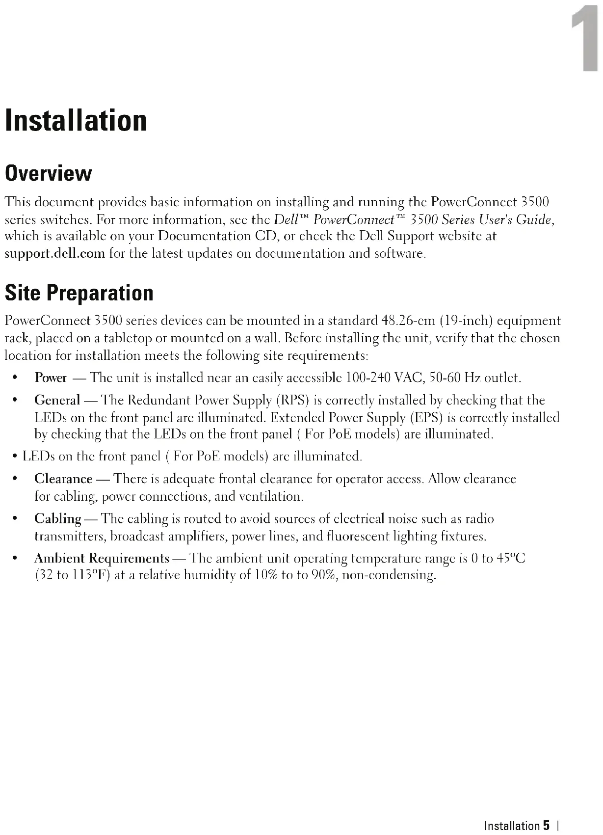
1 Place the supplied rack-mounting bracket on one side of the device, ensuring that the mounting holes on the device line up to the mounting holes on the rack-mounting bracket.
The following figure illustrates where to mount the brackets.
Figure 1-1. Bracket Installation for Rack Mounting
natural_image
Isometric line drawing of a network switch device with multiple ports and connectors (no text or symbols)2 Insert the supplied screws into the rack-mounting holes and tighten with a screwdriver.
3 Repeat the process for the rack-mounting bracket on the other side of the device.
4 Insert the unit into the 48.26-cm (19-inch) rack, ensuring that the rack-mounting holes on the device line up to the mounting holes on the rack.
5 Secure the unit to the rack with the rack screws (not provided). Fasten the lower pair of screws before the upper pair of screws. Ensure that the ventilation holes are not obstructed.
Installing on a Flat Surface
Install the device on a flat surface if it is not installed on a rack. The surface must be able to support the weight of the device and the device cables.
1 Attach the self-adhesive rubber pads on each marked location on the bottom of the chassis.
2 Set the device on a flat surface, leaving 5.08 cm (2 inches) on each side and 12.7 cm (5 inches) at the back.
3 Ensure that the device has proper ventilation.
Installing on a Wall
To mount the switch on a wall:
1 Ensure that the mounting location meets the following requirements:
- The surface of the wall must be capable of supporting the switch.
- Allow at least 5.1 ~cm (2 inches) space on the sides for proper ventilation and 12.7 ~cm (5 inches) at the back for power cable clearance.
• The location must not be exposed to direct sunlight. - The location must be at least 2 feet away from any heating vents, and no area-heating vent should point towards the unit.
• The location must be ventilated to prevent heat buildup. - Do not locate the switch near any data or electrical cabling.
• The power cable must be able to reach an outlet.
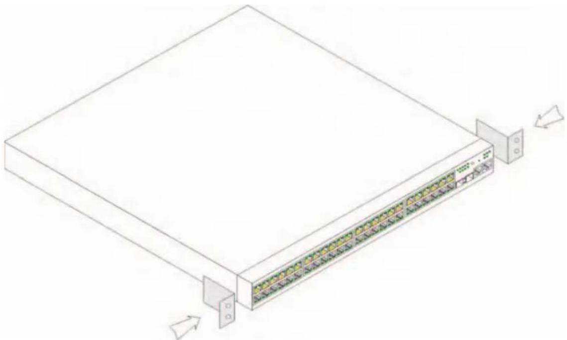
2 Use the supplied screws to attach a mounting bracket to each side of the switch (see the following figure).
Figure 1-2. Bracket Installation for Wall Mounting
natural_image
Isometric line drawing of a rectangular electronic device with internal components and directional arrows indicating flow or movement (no text or symbols)Connecting to a Terminal
1 Connect an RS-232 crossover cable to the ASCII terminal or the serial connector of a desktop system running terminal emulation software.
2 Connect the female DB-9 connector at the other end of the cable to the device serial port connector.

NOTE: Do not connect the power cable to a grounded AC outlet at this time. You have to connect the device to a power source in the steps detailed in Starting and Configuring the Device section.
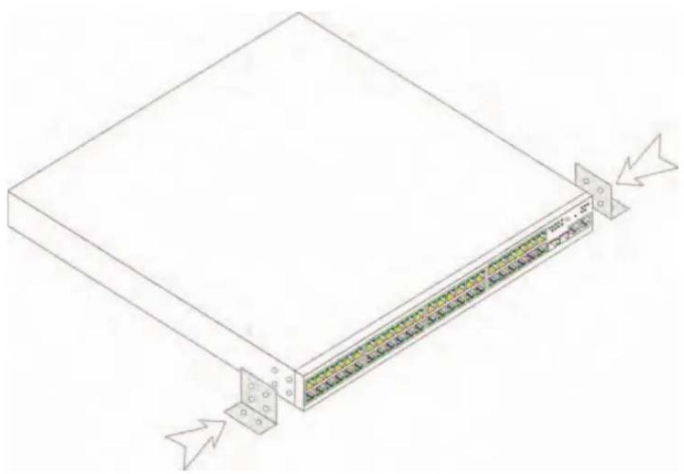
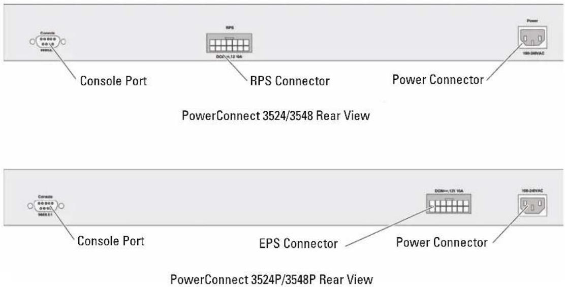
Figure 1-3. Back-Panel Power Connector
text_image
Console 00:00:0 00:10:0 W66.0 Console Port RPS DCB=12 10A RPS Connector Power Connector PowerConnect 3524/3548 Rear View Console 00:00:0 00:10:0 W66.0 Console Port EKS Connector Power Connector DCB=12 10A 108-34VAC PowerConnect 3524P/3548P Rear ViewStacking
Overview
Each device can operate as a stand-alone device or can be a member in a stack. Up to eight devices are supported per stack.
All stacks must have a Master unit, and may have a Master Backup unit, with any other devices connected to the stack as Members.
Stacking PowerConnect 3500 Series Switches
Each PowerConnect 3500 series stack contains a single Master unit, and may have a Master Backup unit, while the remaining units are considered stacking Members.
PowerConnect 3500 series switches use the RJ-45 Gigabit Ethernet ports (G3 and G4) for stacking. This enables added stacking capabilities to the devices without adding additional device accessories.
- To stack the devices together, insert a standard Category 5 cable into port G3 in the device at the top of the stack and into port G4 of the device immediately below it.
- Repeat this process until all devices are connected.
- Connect port G3 of the device at the bottom of stack to the port G4 of the device at the top of the stack.
Figure 2-1. Stacking Cable Diagram

flowchart
graph TD
    A["Server Rack 1"] -->|Ethernet Switch| B["Router"]
    C["Server Rack 2"] -->|Ethernet Switch| D["Router"]
    E["Server Rack 3"] -->|Ethernet Switch| F["Router"]
    G["Router"] -->|Ethernet Switch| H["Router"]
For more information on stacking, see the Dell PowerConnect 3500 Series User's Guide on the Documentation CD.
You can perform the stack unit identification on the device front-panel using the Stack ID button.
Figure 2-2. Stacking Configuration and Identification Panel

text_image
Stacking LEDs Stack ID Button PowerConnect Master 1 2 3 4 5 6 7 8 STACK ID SELECT RESET DIAG RPS PWR FAN TEMP LINKACT FOXPREF G1 G2 G3 G4 Stacking Port DLLEach stack device has a unique identifying unit ID that defines the unit's position and function in the stack. If the device is a stand-alone unit, the Stack LED is not illuminated. The default setting is stand-alone.
You can manually configure the unit ID using the Stack ID button. The unit ID is indicated by the Stack ID LEDs. Unit ID 1 and 2 are reserved for the Master and Backup Master unit, and unit ID 3 to 8 are for Member units.
Unit ID Selection Process
The unit ID selection process is as follows:
1 Power up the device — To power up the device perform the following tasks:
a Ensure that the stand-alone/Master device Console port is connected to a VT100 terminal device or VT100 terminal emulator via the RS-232 crossover cable.
b Locate an AC power receptacle.
c Deactivate the AC power receptacle.
d Connect the device to the AC receptacle.
e Activate the AC power receptacle.
f Confirm that the device is connected and operating correctly by examining the LEDs on the front panel.
When powering up, the configured LED number (corresponding to the previously saved unit ID) begins to flash. The LED flashes for 15 seconds. During this period, you can select a specific Stack ID by pressing the Stack ID button until the appropriate Stack ID LED is illuminated.
2 Selection process — To advance the stacking ID LED number, continue pressing the Stack ID button. When LED 8 is flashing, pressing the Stack ID button results in the device being configured as a standalone. Pressing the Stack ID button again advances the Stack ID to 1. Unit 1 and Unit 2 are master-enabled units; refer to the User Guide for information about the master-selection process.
3 End selection process — The unit ID selection process is completed when the 15-second selection period expires. The Stack ID button becomes unresponsive and the unit ID is set to the LED ID flashing at the end of the period.
NOTE: Perform these steps one unit at a time until all stack members are powered up and their Stack IDs are selected. Performing the steps one unit at a time allows sufficient time to select the Stack ID for each unit. However, the entire stack should be cabled as per the "Stacking Cable Diagram" before powering up the devices.
Starting and Configuring the Device
After completing all external connections, connect a terminal to the device to configure the device. Performing the additional advanced functions are described in the Dell PowerConnect 3500 Series User's Guide on the Documentation CD.
NOTE: Before proceeding further, read the release notes for this product. You can download the release notes from the Dell Support website at support.dell.com.
NOTE: We recommend that you obtain the most recent revision of the user documentation from the Dell Support website at support.dell.com.
Connecting to the Device
To configure the device, the device must be connected to a console, but if the device is part of a stack, only one device called the Master unit in the whole stack needs to be connected to a terminal. You can identify the Master unit by the illuminated Master LED on the front panel of the switch. Because the stack operates as a single device, only the Master unit is configured.
Connecting the Terminal to the Device
The device provides a Console port that enables a connection to a terminal desktop system running terminal emulation software for monitoring and configuring the device. The Console port connector is a male DB-9 connector, implemented as a data terminal equipment (DTE) connector.
To use the Console port, the following is required:
- VT100-compatible terminal or a desktop or portable system with a serial port and running VT100 terminal emulation software
- An RS-232 crossover cable with a female DB-9 connector for the Console port and the appropriate connector for the terminal
To connect a terminal to the device Console port, perform the following tasks:
1 Connect the supplied RS-232 crossover cable to the terminal running VT100 terminal emulation software.
2 Ensure that the terminal emulation software is set as follows:
a Select the appropriate serial port (serial port 1 or serial port 2) to connect to the console.
b Set the data rate to 9600 baud.
c Set the data format to 8 data bits, 1 stop bit, and no parity.
d Set flow control to none.
e Under Properties, select VT100 for Emulation mode.
f Select Terminal keys for Function, Arrow, and Ctrl keys. Ensure that the setting is for Terminal keys (not Windows keys).

NOTICE: When using HyperTerminal with Microsoft® Windows® 2000, Windows XP, or Widows Viste, ensure that you have the latest Service Pack installed. With Windows 2000 Service Pack 2, the arrow keys function properly in HyperTerminal's VT100 emulation. Go to www.microsoft.com for information on Windows 2000, Windows XP, or Widows Viste service packs.
3 Connect the female connector of the RS-232 crossover cable directly to the device Console port on the Master unit/stand-alone device, and tighten the captive retaining screws. The PowerConnect 3500 Series Console port is on the rear panel.
Figure 3-1. Connecting to PowerConnect 3500 series Console Port

text_image
Terminal PowerConnect Rear Panel
NOTE: You can connect a console to the Console port on any unit in the stack, but stack management is performed only from the stack master (unit ID 1 or 2).
Booting the Switch
When the power is turned on with the local terminal already connected, the switch goes through power-on self-test (POST). POST runs every time the device is started and checks hardware components to determine if the device is operational before completely booting. If the system detects a critical problem, the program flow stops. If POST passes successfully, a valid executable image is loaded into RAM. POST messages are displayed on the terminal and indicate test success or failure.
The boot process runs approximately 90 seconds.
Initial Configuration
NOTE: Before proceeding, read the release notes for this product. You can download the release notes from the Dell Support website at support.dell.com.
NOTE: The initial configuration uses the following assumptions:
• The PowerConnect device was never configured before and is in the same state as when you received it.
• The PowerConnect device booted successfully.
- The console connection is established and the console prompt is displayed on the screen of a VT100 terminal device.
The initial device configuration is through the Console port. After the initial configuration, you can manage the device either from the already connected Console port or remotely through an interface defined during the initial configuration.
The system prompts you to use the Set-up wizard when the device boots up for the first time or if the configuration file is empty because the device is not configured. The Setup Wizard provides guidance through the initial device configuration, and gets the device up and running as quickly as possible.
NOTE: Obtain the following information from your network administrator before configuring the device:
- SNMP Community String and SNMP Management System IP address (optional).
- Username and Password.
- The IP address to be assigned to the VLAN 1 interface through which the device is to be managed (by default, every external and internal port is a member of the VLAN 1)
• The IP subnet mask for the network - The default gateway (next hop router) IP address for configuring the default route.
The Setup Wizard guides you through the initial switch configuration, and gets the system up and running as quickly as possible. You can skip using the setup wizard and configure the switch manually through the device CLI mode. Consult the PowerConnect 3500 Series User's Guide for assistance in configuring the device using CLI.
The Setup Wizard configures the following fields.
- SNMP Community String and SNMP Management System IP address (optional)
- Username and Password
- Device IP address
- IP subnet mask
- Default Gateway IP address
The Setup Wizard displays the following information:
Welcome to Dell Easy Setup Wizard
The Setup Wizard guides you through the initial switch configuration, and gets you up and running easily and quickly. You can also skip the setup wizard, and enter CLI mode to manually configure the switch if you prefer. You can exit the setup wizard any time by entering {CNTRL+Z]. The system will prompt you with a default answer. By pressing Enter, you accept the default value.
Would you like to skip the setup wizard? [Y/N] N
If you enter[Y], the Set-up wizard exits. If you do not respond within 60 seconds, the Set-up wizard automatically exits and the CLI console prompt appears.
If you enter [N], the Set-up wizard provides interactive guidance through the initial device configuration.

NOTE: You can exit the setup wizard at any time by entering [CNTRL+Z].

NOTE: If you do not respond to any prompt within 60 seconds, the Set-up wizard automatically exits. And, none of your changes are saved.
Wizard Step 1
The following information displays:
The system is not setup for SNMP management by default. To manage the switch using SNMP (required for Dell Network Manager) you can:
- Setup the initial SNMP version 2 account now.
- Return later and setup the SNMP version account. (For more information on setting up a SNMP version 2 account, see the user documentation).
Would you like to setup the SNMP management interface now? [Y/N] Y
Enter [N] to skip to Step 2.
Enter [Y] to continue the Set-up wizard. The following information displays:
To setup the SNMP management account you must specify the management system IP address and the "community string" or password that the particular management system uses to access the switch. The wizard automatically assigns the highest access level [Privilege Level 15] to this account. You can use Dell Network Manager or other management interfaces to change this setting later, and to add additional management system later. For more information on adding management systems, see the user documentation.
To add a management station:
Please enter the SNMP community string to be used: [MYSETUPWIZARD] >> Dell Network Manager
Please enter the IP address of the Management System (A.B.C.D) or wildcard (0.0.0.0) to manage from any Management Station, for example 192.168.1.10. Press Enter.
Wizard Step 2
The following information displays:
Now we need to setup your initial privilege (Level 15) user account. This account is used to login to the CLI and Web interface. You may setup other accounts and change privilege levels later. For more information on setting up user accounts and changing privilege levels, see the user documentation.
To setup a user account:
Please enter the user name:
Please enter the user password:
Please reenter the user password:
Enter the Following:
- User name, for example "admin"
- Password and password confirmation.

NOTE: The system prompts you if the first and second password entries are not identical.
Press Enter.
Wizard Step 3
The following information displays:
Next, an IP address is setup. The IP address is defined on the default VLAN (VLAN #1), of which all ports are members. This is the IP address you use to access the CLI, Web interface, or SNMP interface for the switch.
To setup an IP address:
Please enter the IP address of the device (A.B.C.D):
Please enter the IP subnet mask (A.B.C.D or /nn):
Enter the IP address and IP subnet mask, for example 192.168.1.100 as the IP address and 255.255.255.0 as the IP subnet mask.
Press Enter.
Wizard Step 4
The following information displays:
Finally, setup the default gateway. Please enter the IP address of the gateway from which this network is reachable (e.g. 192.168.1.1):
Enter the default gateway.
Press Enter. The following is displayed (as per the example parameters described):
This is the configuration information that has been collected:
SNMP Interface = "Dell Network Manager"@192.168.1.10
User Account setup = admin
Password = *********
Management IP address = 192.168.1.100 255.255.255.0
Default Gateway = 192.168.1.1
Wizard Step 5
The following information displays:
If the information is correct, please select (Y) to save the configuration, and copy to the start-up configuration file. If the information is incorrect, select (N) to discard configuration and restart the wizard: [Y/N]
Enter [N] to skip to restart the wizard.
Enter [Y] to complete the Set-up wizard. The following is displayed:
Thank you for using Dell Easy Setup Wizard. You will now enter CLI mode.
Wizard Step 6
The CLI prompt displays. Consult the PowerConnect 3500 Series User's Guide for more information.
natural_image
Isometric line drawing of a server rack with multiple ports and connectors (no text or symbols)natural_image
Isometric line drawing of a rectangular electronic device with internal components and directional arrows indicating flow or movement (no text or symbols)连接至终端
The Setup Wizard guides you through the initial switch configuration, and gets you up and running easily and quickly. You can also skip the setup wizard, and enter CLI mode to manually configure the switch if you prefer. You can exit the setup wizard any time by entering {CNTRL+Z]. The system will prompt you with a default answer.
Would you like to skip the setup wizard? [Y/N] N
(是否跳过安装向导? [Y/N] N)
Now we need to setup your initial privilege (Level 15) user account. This account is used to login to the CLI and Web interface. You may setup other accounts and change privilege levels later. For more information on setting up user accounts and changing privilege levels, see the user documentation. (现在,需要设置初始权限 [级别 15] 用帐。该帐用于登录到 CLI 界面及 Web 界面。稍后,可以设置其它帐并更改权限级别。关设置用帐和更改权限级别的详情,请参阅用说明文件。)
To setup a user account: (要设置用帐:)
Please enter the user name: (请输入名:)
Please enter the user password: (请输入密码:)
Please reenter the user password: (请重新输用密码:)
输入以下内容:
To setup an IP address: (要设置 IP 地址:)
Please enter the IP address of the device (A.B.C.D): (请输入设备的 IP 地址 [A.B.C.D]:)
Please enter the IP subnet mask (A.B.C.D or /nn): (请输入 IP 子网掩码 [A.B.C.D 或 /nn]:)
Finally, setup the default gateway. Please enter the IP address of the gateway from which this network is reachable(e.g. 192.168.1.1): (最后,设置默认网关。请输入通过它可访问网络的网关 IP 地址 [例如,192.168.1.1]:)
输入默认网关。
This is the configuration information that has been collected: (以下是已收集的配置信息:)
SNMP Interface = "Dell Network Manager"@192.168.1.10 (SNMP 界面 = "Dell Network Manager"@192.168.1.10)
User Account setup = admin (用帐设置 = admin)
Instalace na zed. 50
natural_image
Isometric line drawing of a server rack with multiple ports and connectors (no text or symbols)natural_image
Isometric line drawing of a server rack with connectors and ventilation slots (no text or symbols)Welcome to Dell Easy Setup Wizard
The Setup Wizard guides you through the initial switch configuration, and gets you up and running easily and quickly. You can also skip the setup wizard, and enter CLI mode to manually configure the switch if you prefer. You can exit the setup wizard any time by entering {CNTRL+Z}. The system will prompt you with a default answer.
By pressing Enter, you accept the default value.
Would you like to skip the setup wizard? [Y/N] N
The system is not setup for SNMP management by default. To manage the switch using SNMP (required for Dell Network Manager) you can:
- Setup the initial SNMP version 2 account now.
- Return later and setup the SNMP version account. (For more information on setting up a SNMP version 2 account, see the user documentation).
Would you like to setup the SNMP management interface now? [Y/N] Y
To setup the SNMP management account you must specify the management system IP address and the "community string" or password that the particular management system uses to access the switch. The wizard automatically assigns the highest access level [Privilege Level 15] to this account. You can use Dell Network Manager or other management interfaces to change this setting later, and to add additional management system later. For more information on adding management systems, see the user documentation.
To add a management station:
Please enter the SNMP community string to be used: [MYSETUPWIZARD] >> Dell Network Manager
Now we need to setup your initial privilege (Level 15) user account. This account is used to login to the CLI and Web interface. You may setup other accounts and change privilege levels later. For more information on setting up user accounts and changing privilege levels, see the user documentation.
To setup a user account:
Please enter the user name:
Please enter the user password:
Please reenter the user password:
Next, an IP address is setup. The IP address is defined on the default VLAN (VLAN #1), of which all ports are members. This is the IP address you use to access the CLI, Web interface, or SNMP interface for the switch.
To setup an IP address:
Please enter the IP address of the device (A.B.C.D):
Please enter the IP subnet mask (A.B.C.D or /nn):
Finally, setup the default gateway. Please enter the IP address of the gateway from which this network is reachable (e.g. 192.168.1.1):
This is the configuration information that has been collected:
SNMP Interface = "Dell Network Manager"@192.168.1.10
User Account setup = admin
Password = *****
Management IP address = 192.168.1.100 255.255.255.0
Default Gateway = 192.168.1.1
Průvodce - krok 5
If the information is correct, please select (Y) to save the configuration, and copy to the start-up configuration file. If the information is incorrect, select (N) to discard configuration and restart the wizard: [Y/N]
Thank you for using Dell Easy Setup Wizard. You will now enter CLI mode.
Průvodce - krok 6
natural_image
Isometric line drawing of a server rack with ports and connectors, no text or symbols presentnatural_image
Isometric line drawing of a server rack with ports and connectors, showing internal structure and directional arrows (no text or symbols)Welcome to Dell Easy Setup Wizard
The Setup Wizard guides you through the initial switch configuration, and gets you up and running easily and quickly. You can also skip the setup wizard, and enter CLI mode to manually configure the switch if you prefer. You can exit the setup wizard any time by entering {Ctrl+Z]. The system will prompt you with a default answer. By pressing Enter, you accept the default value.
Would you like to skip the setup wizard? [Y/N] N
The system is not setup for SNMP management by default. To manage the switch using SNMP (required for Dell Network Manager) you can:
- Setup the initial SNMP version 2 account now.
- Return later and setup the SNMP version account. (For more information on setting up a SNMP version 2 account, see the user documentation).
Would you like to setup the SNMP management interface now? [Y/N] Y
To setup the SNMP management account you must specify the management system IP address and the "community string" or password that the particular management system uses to access the switch. The wizard automatically assigns the highest access level [Privilege Level 15] to this account. You can use Dell Network Manager or other management interfaces to change this setting later, and to add additional management system later. For more information on adding management systems, see the user documentation.
To add a management station:
Please enter the SNMP community string to be used: [MYSETUPWIZARD] >> Dell Network Manager
Now we need to setup your initial privilege (Level 15) user account. This account is used to login to the CLI and Web interface. You may setup other accounts and change privilege levels later. For more information on setting up user accounts and changing privilege levels, see the user documentation.
To setup a user account:
Please enter the user name:
Please enter the user password:
Please reenter the user password:
Next, an IP address is setup. The IP address is defined on the default VLAN (VLAN #1), of which all ports are members. This is the IP address you use to access the CLI, Web interface, or SNMP interface for the switch.
To setup an IP address:
Please enter the IP address of the device (A.B.C.D):
Please enter the IP subnet mask (A.B.C.D or /nn):
Finally, setup the default gateway. Please enter the IP address of the gateway from which this network is reachable (e.g. 192.168.1.1):
This is the configuration information that has been collected:
SNMP Interface = "Dell Network Manager"@192.168.1.10
User Account setup = admin
Password = *****
Management IP address = 192.168.1.100 255.255.255.0
Default Gateway = 192.168.1.1
Assistant - Étape 5
If the information is correct, please select (Y) to save the configuration, and copy to the start-up configuration file.
If the information is incorrect, select (N) to discard configuration and restart the wizard: [Y/N]
Thank you for using Dell Easy Setup Wizard. You will now enter CLI mode.
Assistant - Étape 6
natural_image
Isometric line drawing of a server rack with multiple ports and connectors (no text or symbols)natural_image
Isometric line drawing of a server rack with connectors and ventilation slots (no text or symbols)Welcome to Dell Easy Setup Wizard
The Setup Wizard guides you through the initial switch configuration, and gets you up and running easily and quickly. You can also skip the setup wizard, and enter CLI mode to manually configure the switch if you prefer. You can exit the setup wizard any time by entering {CNTRL+Z]. The system will prompt you with a default answer.
By pressing Enter, you accept the default value.
Would you like to skip the setup wizard? [Y/N] N
The system is not setup for SNMP management by default. To manage the switch using SNMP (required for Dell Network Manager) you can:
- Setup the initial SNMP version 2 account now.
- Return later and setup the SNMP version account. (For more information on setting up a SNMP version 2 account, see the user documentation).
Would you like to setup the SNMP management interface now? [Y/N] Y
To setup the SNMP management account you must specify the management system IP address and the "community string" or password that the particular management system uses to access the switch. The wizard automatically assigns the highest access level [Privilege Level 15] to this account. You can use Dell Network Manager or other management interfaces to change this setting later, and to add additional management system later. For more information on adding management systems, see the user documentation.
To add a management station:
Please enter the SNMP community string to be used: [MYSETUPWIZARD] >> Dell Network Manager
Now we need to setup your initial privilege (Level 15) user account. This account is used to login to the CLI and Web interface. You may setup other accounts and change privilege levels later. For more information on setting up user accounts and changing privilege levels, see the user documentation.
To setup a user account:
Please enter the user name:
Please enter the user password:
Please reenter the user password:
Next, an IP address is setup. The IP address is defined on the default VLAN (VLAN #1), of which all ports are members. This is the IP address you use to access the CLI, Web interface, or SNMP interface for the switch.
To setup an IP address:
Please enter the IP address of the device (A.B.C.D):
Please enter the IP subnet mask (A.B.C.D or /nn):
Finally, setup the default gateway. Please enter the IP address of the gateway from which this network is reachable (e.g. 192.168.1.1):
This is the configuration information that has been collected:
SNMP Interface = "Dell Network Manager"@192.168.1.10
User Account setup = admin
Password = *****
Management IP address = 192.168.1.100 255.255.255.0
Default Gateway = 192.168.1.1
If the information is correct, please select (Y) to save the configuration, and copy to the start-up configuration file. If the information is incorrect, select (N) to discard configuration and restart the wizard: [Y/N]
Thank you for using Dell Easy Setup Wizard. You will now enter CLI mode.
natural_image
Isometric line drawing of a server rack with ports and connectors, no text or symbols presentnatural_image
Isometric line drawing of a server rack with connectors and ventilation slots (no text or symbols)Welcome to Dell Easy Setup Wizard
The Setup Wizard guides you through the initial switch configuration, and gets you up and running easily and quickly. You can also skip the setup wizard, and enter CLI mode to manually configure the switch if you prefer. You can exit the setup wizard any time by entering CNTRL+Z . The system will prompt you with a default answer. By pressing Enter, you accept the default value.
Would you like to skip the setup wizard? [Y/N] N
The system is not setup for SNMP management by default. To manage the switch using SNMP (required for Dell Network Manager) you can:
- Setup the initial SNMP version 2 account now.
- Return later and setup the SNMP version account. (For more information on setting up a SNMP version 2 account, see the user documentation).
Would you like to setup the SNMP management interface now? [Y/N] Y
To setup the SNMP management account you must specify the management system IP address and the "community string" or password that the particular management system uses to access the switch. The wizard automatically assigns the highest access level [Privilege Level 15] to this account. You can use Dell Network Manager or other management interfaces to change this setting later, and to add additional management system later. For more information on adding management systems, see the user documentation.
To add a management station:
Please enter the SNMP community string to be used: [MYSETUPWIZARD] >> Dell Network Manager
Now we need to setup your initial privilege (Level 15) user account. This account is used to login to the CLI and Web interface. You may setup other accounts and change privilege levels later. For more information on setting up user accounts and changing privilege levels, see the user documentation.
To setup a user account:
Please enter the user name:
Please enter the user password:
Please reenter the user password:
Next, an IP address is setup. The IP address is defined on the default VLAN (VLAN #1), of which all ports are members. This is the IP address you use to access the CLI, Web interface, or SNMP interface for the switch.
To setup an IP address:
Please enter the IP address of the device (A.B.C.D):
Please enter the IP subnet mask (A.B.C.D or /nn):
Finally, setup the default gateway. Please enter the IP address of the gateway from which this network is reachable (e.g. 192.168.1.1):
This is the configuration information that has been collected:
SNMP Interface = "Dell Network Manager"@192.168.1.10
User Account setup = admin
Password = *********
Management IP address = 192.168.1.100 255.255.255.0
Default Gateway = 192.168.1.1
Βήμα 5 του οδηγού
If the information is correct, please select (Y) to save the configuration, and copy to the start-up configuration file. If the information is incorrect, select (N) to discard configuration and restart the wizard: [Y/N]
Thank you for using Dell Easy Setup Wizard. You will now enter CLI mode.
Βήμα 6 του οδηγού
natural_image
Isometric line drawing of a server rack with multiple ports and connectors, showing internal structure and connection arrows (no text or symbols)natural_image
Isometric line drawing of a rectangular electronic device with internal components and directional arrows indicating flow or movement (no text or symbols)ターミナルへの接続
Welcome to Dell Easy Setup Wizard
The Setup Wizard guides you through the initial switch configuration, and gets you up and running easily and quickly. You can also skip the setup wizard, and enter CLI mode to manually configure the switch if you prefer. You can exit the setup wizard any time by entering {CNTRL+Z]. The system will prompt you with a default answer. By pressing Enter, you accept the default value.
Would you like to skip the setup wizard? [Y/N] N
The system is not setup for SNMP management by default. To manage the switch using SNMP (required for Dell Network Manager) you can:
- Setup the initial SNMP version 2 account now.
- Return later and setup the SNMP version account. (For more information on setting up a SNMP version 2 account, see the user documentation).
Would you like to setup the SNMP management interface now? [Y/N] Y
To setup the SNMP management account you must specify the management system IP address and the "community string" or password that the particular management system uses to access the switch. The wizard automatically assigns the highest access level [Privilege Level 15] to this account. You can use Dell Network Manager or other management interfaces to change this setting later, and to add additional management system later. For more information on adding management systems, see the user documentation.
To add a management station:
Please enter the SNMP community string to be used: [MYSETUPWIZARD] >> Dell Network Manager
Now we need to setup your initial privilege (Level 15) user account. This account is used to login to the CLI and Web interface. You may setup other accounts and change privilege levels later. For more information on setting up user accounts and changing privilege levels, see the user documentation.
To setup a user account:
Please enter the user name:
Please enter the user password:
Please reenter the user password:
以下の入力を行います。
Next, an IP address is setup. The IP address is defined on the default VLAN (VLAN #1), of which all ports are members. This is the IP address you use to access the CLI, Web interface, or SNMP interface for the switch.
To setup an IP address:
Please enter the IP address of the device (A.B.C.D):
Please enter the IP subnet mask (A.B.C.D or /nn):
Finally, setup the default gateway. Please enter the IP address of the gateway from which this network is reachable (e.g. 192.168.1.1):
デフォルトゲートウェイを入力します。
This is the configuration information that has been collected:
SNMP Interface = "Dell Network Manager"@192.168.1.10
User Account setup = admin
Password = *****
Management IP address = 192.168.1.100 255.255.255.0
Default Gateway = 192.168.1.1
ウィザード手順5
以下の情報が表示されます。
If the information is correct, please select (Y) to save the configuration, and copy to the start-up configuration file. If the information is incorrect, select (N) to discard configuration and restart the wizard: [Y/N]
Thank you for using Dell Easy Setup Wizard. You will now enter CLI mode.
ウィザード手順6
natural_image
Isometric line drawing of a server rack with multiple ports and connectors (no text or symbols)natural_image
Isometric line drawing of a rectangular electronic device with internal components and directional arrows indicating flow or movement (no text or symbols)터미널에 연결
The Setup Wizard guides you through the initial switch configuration, and gets you up and running easily and quickly. You can also skip the setup wizard, and enter CLI mode to manually configure the switch if you prefer. You can exit the setup wizard any time by entering CNTRL+Z . The system will prompt you with a default answer.
By pressing Enter, you accept the default value.
Would you like to skip the setup wizard? [Y/N] N
The system is not setup for SNMP management by default. To manage the switch using SNMP (required for Dell Network Manager) you can:
- Setup the initial SNMP version 2 account now.
- Return later and setup the SNMP version account. (For more information on setting up a SNMP version 2 account, see the user documentation).
To setup the SNMP management account you must specify the management system IP address and the "community string" or password that the particular management system uses to access the switch. The wizard automatically assigns the highest access level [Privilege Level 15] to this account. You can use Dell Network Manager or other management interfaces to change this setting later, and to add additional management system later. For more information on adding management systems, see the user documentation.
To add a management station:
Please enter the SNMP community string to be used: [MYSETUPWIZARD] >> Dell Network Manager
Now we need to setup your initial privilege (Level 15) user account. This account is used to login to the CLI and Web interface. You may setup other accounts and change privilege levels later. For more information on setting up user accounts and changing privilege levels, see the user documentation.
To setup a user account:
Please enter the user name:
Please enter the user password:
Please reenter the user password:
다음을 입력합니다.
Next, an IP address is setup. The IP address is defined on the default VLAN (VLAN #1), of which all ports are members. This is the IP address you use to access the CLI, Web interface, or SNMP interface for the switch.
To setup an IP address:
Please enter the IP address of the device (A.B.C.D):
Please enter the IP subnet mask (A.B.C.D or /nn):
Finally, setup the default gateway. Please enter the IP address of the gateway from which this network is reachable (e.g. 192.168.1.1):
기본 게이트웨이를 입력합니다.
This is the configuration information that has been collected:
SNMP Interface = "Dell Network Manager"@192.168.1.10
User Account setup = admin
Password = *********
Management IP address = 192.168.1.100 255.255.255.0
Default Gateway = 192.168.1.1
마법사 단계 5
다음과 같은 메시지가 표시됩니다.
If the information is correct, please select (Y) to save the configuration, and copy to the start-up configuration file. If the information is incorrect, select (N) to discard configuration and restart the wizard: [Y/N]
Thank you for using Dell Easy Setup Wizard. You will now enter CLI mode.
마법사 단계 6
natural_image
Isometric line drawing of a server rack with multiple Ethernet ports and connections, no text or symbols present.natural_image
Isometric line drawing of a rectangular electronic device with internal components and directional arrows indicating flow or movement (no text or symbols)Welcome to Dell Easy Setup Wizard
The Setup Wizard guides you through the initial switch configuration, and gets you up and running easily and quickly. You can also skip the setup wizard, and enter CLI mode to manually configure the switch if you prefer. You can exit the setup wizard any time by entering {CNTRL+Z}. The system will prompt you with a default answer. By pressing Enter, you accept the default value.
Would you like to skip the setup wizard? [Y/N] N
The system is not setup for SNMP management by default. To manage the switch using SNMP (required for Dell Network Manager) you can:
- Setup the initial SNMP version 2 account now.
- Return later and setup the SNMP version account. (For more information on setting up a SNMP version 2 account, see the user documentation).
Would you like to setup the SNMP management interface now? [Y/N] Y
To setup the SNMP management account you must specify the management system IP address and the "community string" or password that the particular management system uses to access the switch. The wizard automatically assigns the highest access level [Privilege Level 15] to this account. You can use Dell Network Manager or other management interfaces to change this setting later, and to add additional management system later. For more information on adding management systems, see the user documentation.
To add a management station:
Please enter the SNMP community string to be used: [MYSETUPWIZARD] >> Dell Network Manager
Now we need to setup your initial privilege (Level 15) user account. This account is used to login to the CLI and Web interface. You may setup other accounts and change privilege levels later. For more information on setting up user accounts and changing privilege levels, see the user documentation.
To setup a user account:
Please enter the user name:
Please enter the user password:
Please reenter the user password:
Next, an IP address is setup. The IP address is defined on the default VLAN (VLAN #1), of which all ports are members. This is the IP address you use to access the CLI, Web interface, or SNMP interface for the switch.
To setup an IP address:
Please enter the IP address of the device (A.B.C.D):
Please enter the IP subnet mask (A.B.C.D or /nn):
Finally, setup the default gateway. Please enter the IP address of the gateway from which this network is reachable (e.g. 192.168.1.1):
This is the configuration information that has been collected:
SNMP Interface = "Dell Network Manager"@192.168.1.10
User Account setup = admin
Password = *****
Management IP address = 192.168.1.100 255.255.255.0
Default Gateway = 192.168.1.1
Krok 5. kreatora
If the information is correct, please select (Y) to save the configuration, and copy to the start-up configuration file. If the information is incorrect, select (N) to discard configuration and restart the wizard: [Y/N]
Thank you for using Dell Easy Setup Wizard. You will now enter CLI mode.
Krok 6. kreatora
natural_image
Isometric line drawing of a network switch device with multiple ports and connectors (no text or symbols)natural_image
Isometric line drawing of a server rack with connectors and ventilation slots (no text or symbols)Welcome to Dell Easy Setup Wizard
The Setup Wizard guides you through the initial switch configuration, and gets you up and running easily and quickly. You can also skip the setup wizard, and enter CLI mode to manually configure the switch if you prefer. You can exit the setup wizard any time by entering [CNTRL+Z]. The system will prompt you with a default answer. By pressing Enter, you accept the default value.
Would you like to skip the setup wizard? [Y/N] N)
The system is not setup for SNMP management by default. To manage the switch using SNMP (required for Dell Network Manager) you can:
- Setup the initial SNMP version 2 account now.
- Return later and setup the SNMP version account. (For more information on setting up a SNMP version 2 account, see the user documentation).
Would you like to setup the SNMP management interface now? [Y/N] Y
Pulse [N] para ir al paso 2.
To setup the SNMP management account you must specify the management system IP address and the "community string" or password that the particular management system uses to access the switch. The wizard automatically assigns the highest access level [Privilege Level 15] to this account. You can use Dell Network Manager or other management interfaces to change this setting later, and to add additional management system later. For more information on adding management systems, see the user documentation.
To add a management station:
Please enter the SNMP community string to be used: [MYSETUPWIZARD] >> Dell Network Manager
Now we need to setup your initial privilege (Level 15) user account. This account is used to login to the CLI and Web interface. You may setup other accounts and change privilege levels later. For more information on setting up user accounts and changing privilege levels, see the user documentation.
To setup a user account:
Please enter the user name:
Please enter the user password:
Please reenter the user password:
Next, an IP address is setup. The IP address is defined on the default VLAN (VLAN #1), of which all ports are members. This is the IP address you use to access the CLI, Web interface, or SNMP interface for the switch.
To setup an IP address:
Please enter the IP address of the device (A.B.C.D):
Please enter the IP subnet mask (A.B.C.D or /nn):
Finally, setup the default gateway. Please enter the IP address of the gateway from which this network is reachable (e.g. 192.168.1.1):
This is the configuration information that has been collected:
SNMP Interface = "Dell Network Manager"@192.168.1.10
User Account setup = admin
Password = **********
Management IP address = 192.168.1.100 255.255.255.0
Default Gateway = 192.168.1.1
If the information is correct, please select (Y) to save the configuration, and copy to the start-up configuration file. If the information is incorrect, select (N) to discard configuration and restart the wizard: [Y/N]
Thank you for using Dell Easy Setup Wizard. You will now enter CLI mode.
Management IP address = 192.168.1.100 255.255.255.0
Default Gateway = 192.168.1.1
) 1908.10. 77187
(192.168.1.10 = "Dell Network Manager" = SNMP punn
192.168.1.1 = 77ππ π π π π π π π π π π π π π π π π π π π π π π π π π π π π π π π π π π π π π π π π π π π π π π π π π π π π π π π π π π π π π π π π π π π π π π π π π π π π π π π π π π π π π π π π π π π π π π π π π π π ππ
הכלה 5
: כְרָה אַתִים
If the information is correct, please select (Y) to save the configuration, and copy to the start-up configuration file. If the information is incorrect, select (N) to discard configuration and restart the wizard: [Y/N]
Thank you for using Dell Easy Setup Wizard. You will now enter CLI mode.
.(CLI 127-127-127-127-127-127-127-127-127-127-127)
הכלה 6 tyv
.PowerConnect 3500.
תָרְשָׁה בַרְשָׁה
Next, an IP address is setup. The IP address is defined on the default VLAN (VLAN #1), of which all ports are members. This is the IP address you use to access the CLI, Web interface, or SNMP interface for the switch.
To setup an IP address:
Please enter the IP address of the device (A.B.C.D):
Please enter the IP subnet mask (A.B.C.D or /nn):
Finally, setup the default gateway. Please enter the IP address of the gateway from which this network is reachable (e.g. 192.168.1.1):
This is the configuration information that has been collected:
SNMP Interface = "Dell Network Manager" = 192.168.1.10
User Account setup = admin
Now we need to setup your initial privilege (Level 15) user account. This account is used to login to the CLI and Web interface. You may setup other accounts and change privilege levels later. For more information on setting up user accounts and changing privilege levels, see the user documentation.
To setup a user account:
Please enter the user name:
Please enter the user password:
Please reenter the user password:
The system is not setup for SNMP management by default. To manage the switch using SNMP (required for Dell Network Manager) you can:
- Setup the initial SNMP version 2 account now.
- Return later and setup the SNMP version account. (For more information on setting up a SNMP version 2 account, see the user documentation).
Would you like to setup the SNMP management interface now? [Y/N] Y
To setup the SNMP management account you must specify the management system IP address and the "community string" or password that the particular management system uses to access the switch. The wizard automatically assigns the highest access level [Privilege Level 15] to this account. You can use Dell Network Manager or other management interfaces to change this setting later, and to add additional management system later. For more information on adding management systems, see the user documentation.
To add a management station:
Please enter the SNMP community string to be used: [MYSETUPWIZARD] >> Dell Network Manager
Welcome to Dell Easy Setup Wizard
The Setup Wizard guides you through the initial switch configuration, and gets you up and running easily and quickly. You can also skip the setup wizard, and enter CLI mode to manually configure the switch if you prefer. You can exit the setup wizard any time by entering {CNTRL+Z]. The system will prompt you with a default answer. By pressing Enter, you accept the default value.
Would you like to skip the setup wizard? [Y/N] N
.הכלההוּרָהוּרָהוּרָהוּרָהוּרָהוּרָהוּרָהוּרָהוּרָהוּרָהוּרָהוּרָהוּרָהוּרָהוּרָה
text_image
Ctrl PowerConnect by Windows nitsData Terminal, 数据 Storage, DB-9, 数据 Storage, and Data Terminal (DTE) Equipment
text_image
Console MILK 1 R'US YOL EPS OutputPowerConnect 3524P/3548P
תְקַרָה בְּרָה
natural_image
Isometric line drawing of a server rack with multiple ports and connectors (no text or symbols)2
3548P,3548,3524P,3524
A01
FG745 כְרָה אַתְבּ
2007
PowerConnect™ 35xx
Dell™ 7u
תְרָה בַרִי הַלְרָה