
PowerConnect 2716 - Switch DELL - Free user manual and instructions
Find the device manual for free PowerConnect 2716 DELL in PDF.
| Product type | Managed network switch |
| Model | PowerConnect 2716 |
| Brand | Dell |
| Number of ports | 16 ports Ethernet 10/100 |
| Power supply | 100-240 V AC, 50-60 Hz |
| Power consumption | Approximately 30 W (estimated) |
| Dimensions (W x D x H) | 440 x 230 x 44 mm (estimated) |
| Weight | Approximately 2.5 kg (estimated) |
| Operating temperature | 0 °C to 45 °C |
| Relative humidity | Up to 95% non-condensing |
| Mounting options | Desktop, 19-inch rack, wall |
| Management interface | Web (HTTP), command line (CLI) via console |
| Basic functions | Auto-negotiation, automatic MDI/MDIX detection, flow control |
| Advanced features | VLAN, QoS, link aggregation, port mirroring |
| LED indicators | Power, per-port activity, speed |
| Package contents | Switch, power cord, rubber feet, mounting kit, documentation CD, guide |
| Safety | Follow installation precautions, disconnect before mounting, adequate ventilation |
| Maintenance | Clean with a dry cloth, avoid liquids, check ventilation |
| Repairability | Spare parts not detailed; contact Dell support for defective components |
Frequently Asked Questions - PowerConnect 2716 DELL
User questions about PowerConnect 2716 DELL
0 question about this device. Answer the ones you know or ask your own.
Ask a new question about this device
Download the instructions for your Switch in PDF format for free! Find your manual PowerConnect 2716 - DELL and take your electronic device back in hand. On this page are published all the documents necessary for the use of your device. PowerConnect 2716 by DELL.
USER MANUAL PowerConnect 2716 DELL
Models: PC2708, PC2716, PC2724, and PC2748
Dell™ PowerConnect™ 27XX Systems
Getting Started Guide
Notes, Notices, and Cautions
NOTE: A NOTE indicates important information that helps you make better use of your device.
NOTICE: A NOTICE indicates either potential damage to hardware or loss of data and tells you how to avoid the problem.
CAUTION: A CAUTION indicates a potential for property damage, personal injury, or death.
Information in this document is subject to change without notice.
2004 - 2006 Dell Inc. All rights reserved.
Reproduction in any manner whatsoever without the written permission of Dell Inc. is strictly forbidden.
Trademarks used in this text: Dell, Dell OpenManage, PowerEdge, the DELL logo, Inspiron, Dell Precision, Dimension, OptiPlex, PowerConnect, PowerApp, PowerVault, Axim, DellNet, and Latitude are trademarks of Dell Inc. Microsoft and Windows are registered trademarks of Microsoft Corporation.
Other trademarks and trade names may be used in this document to refer to either the entities claiming the marks and names or their products. Dell Inc. disclaims any proprietary interest in trademarks and trade names other than its own.
Models:PC2708,PC2716,PC2724,and PC2748
November 2006 P/N T9021 Rev. A02
Contents
Installation 5
Overview 5
Site Preparation. 5
Unpacking. 5
Mounting the Device 6
Starting and Configuring the Device 10
Booting the Switch 10
Initial Configuration 10
Installation
Overview
This document provides basic information to install and start running the PowerConnect 27xx Scrics system. For more information, see the Dell™ PowerConnect™ 27xx Series User's Guide, which is available on your Documentation CD, or check the Dell Support website at support.dell.com for the latest updates on documentation and software.
Site Preparation
PowerConnect 27xx Series devices can be mounted in a standard 48.26-cm (19-inch) equipment rack, placed on a tabletop or mounted on a wall. Before installing the unit, verify that the chosen location for installation meets the following site requirements:
- Power — The unit is installed near an easily accessible 100-240 VAC, 50 - 60Hz outlet. Ensure that after connection, the power LED on the device is visible.
- Clearance — There is adequate frontal clearance for operator access. Allow clearance for cabling, power connections, and ventilation.
- Cabling — The cabling is routed to avoid sources of electrical noise such as radio transmitters, broadcast amplifiers, power lines, and fluorescent lighting fixtures.
- Ambient Requirements - The ambient unit operating temperature range is 0 to 45^ (32 to 113^ ) at a relative humidity of up to 95 percent, non condensing.
Unpacking
Package Contents
While unpacking the device, ensure that the following items are included:
- Devicc/Switch
- AC power cable
- Self-adhesive rubber pads
- Mounting kit for rack installation or wall installation
- Documentation CD
Product Information Guide
Unpacking the Device
NOTE: Before unpacking the device, inspect the package and immediately report any evidence of damage.
1 Place the box on a clean flat surface.
2 Open the box or remove the box top.
3 Carefully remove the device from the box and place it on a secure and clean surface.
4 Remove all packing material.
5 Inspect the device and accessories for damage. Report any damage immediately.
Mounting the Device
The following mounting instructions apply to the PowerConnect 27xx Series devices. There are three device mounting options:
- Installing on a Flat Surface
- Installing in a Rack
- Installing on a Wall
Installing on a Flat Surface
The device must be installed on a flat surface if it is not installed in a rack or on a wall. The surface must be able to support the weight of the device and the device cables.
1 Attach the self-adhesive rubber pads on each marked location on the bottom of the chassis.
2 Set the device on a flat surface, leaving 5.08cm (2 inches) on each side and 12.7cm (5 inches) at the back.
3 Ensure that the device has proper ventilation.
Installing in a Rack

CAUTION: Disconnect all cables from the unit before mounting the device in a rack or cabinet.

CAUTION: Read the safety information in the Product information Guide as well as the safety information for other devices that connect to or support the switch.

CAUTION: When mounting multiple devices into a rack, mount the devices from the bottom up.
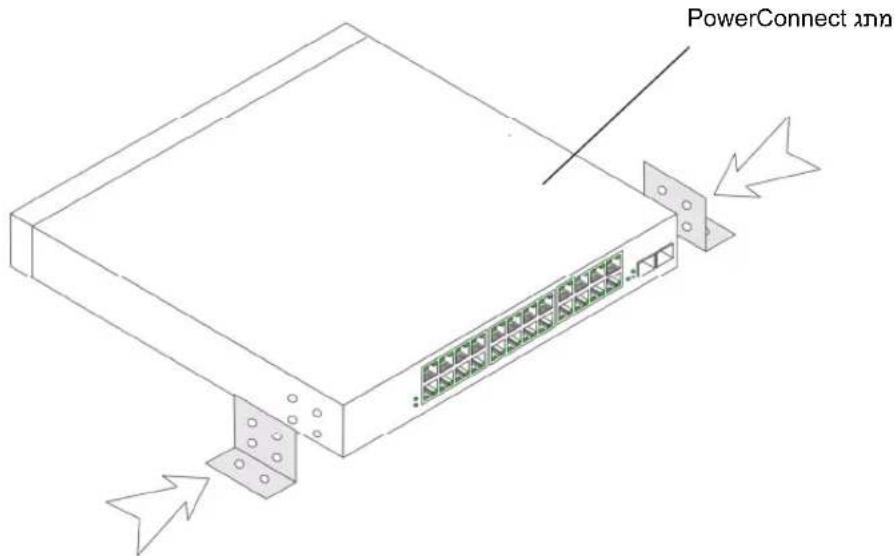
1 Place the supplied rack-mounting bracket on one side of the device, ensuring that the mounting holes on the device line up to the mounting holes on the rack-mounting bracket. The following figure illustrates where to mount the brackets.
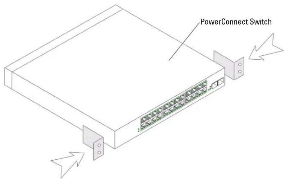
Figure 1-1. Bracket Installation for Rack Mounting
2 Insert the supplied screws into the holes on the sides of the device and tighten with a screwdriver.
3 Repeat the process for the rack-mounting bracket on the other side of the device.
4 Insert the unit into the 48.26-cm (19-inch) rack, ensuring that the rack-mounting holes on the device line up to the mounting holes on the rack.
5 Secure the unit to the rack with the rack screws (not provided). Fasten the lower pair of screws before the upper pair of screws. Ensure that the ventilation holes are not obstructed.
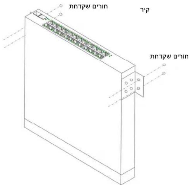
Installing on a Wall
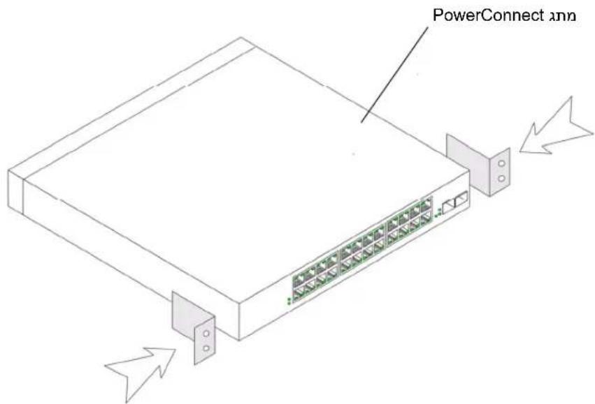
1 Place the supplied wall-mounting bracket on one side of the device, ensuring that the mounting holcs on the device line up to the mounting holes on the rack-mounting bracket. The following figure illustrates where to mount the brackets.
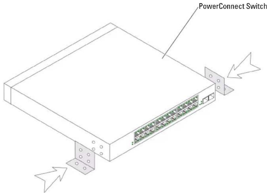
Figure 1-2. Bracket Installation for Wall Mounting
2 Insert the supplied screws into the rack-mounting holcs and tighten with a screwdriver.
3 Repeat the process for the wall-mounting bracket on the other side of the device.
4 Place the device against the wall and mark the wall through the bracket holes.
5 Drill holes in the wall for the brackets and install the appropriate mounting hardware (not supplicd).
6 Place the device against the wall so that the bracket holes align with the holes in the wall.
7 Insert and tighten the screws through each of the mounting brackets. Ensure that the ventilation holes are not obstructed.

Figure 1-3. Mounting Device on Wall
Connecting a Device to a Power Supply
Connect the supplied AC power cable to the AC power connector on the back panel.

NOTE: Do not connect the power cable to a grounded AC outlet at this time. You will connect the device to a power source in the steps detailed in Starting and Configuring the Device.
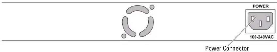
Figure 1-4. Back-Panel Power Connectors
PowerConnect Switch Rear View
Connect the device to an AC outlet. After you have connected the device to a power source, confirm that the device is connected and operating correctly by examining the LEDs on the front panel.
Starting and Configuring the Device

NOTE: The device is designed to function as an unmanaged switch without any configuration of the management interface. Setup of the management interface is not a requirement if the switch is deployed as an unmanaged switch. To use the management functions, refer the configuration options and details in the User's Guide on the enclosed CD. Without specific configuration, the device functions with the default settings, as described in the User's Guide.

NOTE: Before proceeding, read the release notes for this product. You can download the release notes from the Dell Support website at support.dell.com.

NOTE: It is recommended that you obtain the most recent revision of the user documentation from the Dell Support website at support.dell.com.
Booting the Switch
When the device is connected to a power source, the device LEDs glow indicating that power is being supplied to the device. A power-on self-test (POST) runs every time the device is initialized and checks hardware components to determine if the device is fully operational before completely booting. If POST passes successfully, the System and the Power LEDs glow and a valid executable image is loaded into RAM.
The boot process runs approximately 90 seconds.
Initial Configuration

NOTE: The initial configuration uses the following assumptions:
- The PowerConnect device is configured with the pre configured default IP (192.168.2.1) and subnet mask (255.255.255.0).
- The PowerConnect device booted successfully.
To begin using the device, it is advisable to configure the device with the system specific configuration.

NOTE: Obtain the following information from the network administrator before configuring the device:
The IP address to be assigned to the VLAN 1 interface through which the device is to be managed
The IP subnet mask for the network
The default gateway (next hop router) IP address for configuring the default route.
To configure the device:
1 Open the web management interface (from any desktop or workstation). To do so, enter the IP address of the device in the URI field of a web browser.

NOTE: The web management interface supports the following web browsers: Microsoft Internet Explorer 6.x or above and Mozilla Version 1.7.x or above.
2 In the Web user interface, Click IP Addressing. The System IP Address window appears.
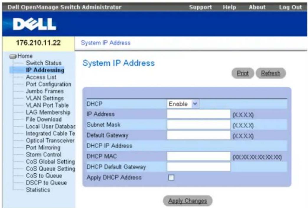
3 Enter the IP Address, Subnet Mask and Default Gateway.
4 Click Apply Changes. The device is configured.

NOTE: This getting started guide provides information on the steps necessary for basic setup of the switch. For more information on the management capabilities of the switch, please refer the PowerConnect 27xx Series User's Guide found on your documentation CD.
Systémy Dell™ PowerConnect™ 27xx
Začinámě
November 2006 P/N T9021 Rev. A02
Inhalt
Installation 41
Ubersicht 41
© 2004-2006 Dell Inc. All rights reserved.
System IP Address (IP地址) IP Addressing (IP地址)

Jn nn nnnnnnnnnnnnnnnnnnnnnnnnnnnnnnnnnnnnnnnnnnnnnnnnnnnnnnnnnnnnnnnnnnnnnnnnnnnnnnnnnnnnnnnnnnnnnnnnnnnnnnnnnnnnnnnnnnnnnnnnnnnnnnnnnnnnnnnnnnnnnnnnnnnnnnnnnnn
y ynnn nn nnnn nn nnnn nn nnnn nn nnnn nn nnnn nn nnnn nn nnnn nn nnnn nn nnnn nn nnnn nn nnnn nn nnnn nn nnnn nn nnnn nn nnnn nn nnnn nn nnnn nn nnnn nn nnnn nn nnnn nn nnnn nn nnnn nn nnnn nn nnnn nn nnnn nn
jnnn nn nynn
y nnnn nn nnnn nn nnnn nn nnnn nn nnnn nn nnnn nn nnnn nn nnnn nn nnnn nn nnnn nn nnnn nn nnnn nn nnnn nn nnnn nn nnnn nn nnnn nn nnnn nn nnnn nn nnnn nn nnnn nn nnnn nn nnnn nn nnnn nn nnnn nn nnnn nn nnnn
y .support.dell.com nnd Dell
nnd Dell w noann nnennnn nnnn nn nnnn nn nnnn .support.dell.com
nnn nnny
wnn np IP wnnn nn noon
n nn nnnn nn (nn hop an) nn nn nn nn IP na
1.3
nnn790h jnn nn
nnn nn nnnnnnnnnnnnnnnnnnnnnnnnn
"
n nn nnn .1.4

Power Connect
ywn nnynn ne,ynnn nnnnn nn nn nnnn nn nnnn nn nnnn nn nnnn nn nnnn nn nnnn nn
77 by npnn
nnnnn nn nnnnnnnnnnnnnnnnnnnnnnnnnnnnnnnnnnnnnnnnnnnnnnnnnnnnnnnnnnnnnnnnnnnnnnnnnnnnnnnnnnnnnnnnnnnnnnnnnnnnnnnnnnnnnnnnnnnnnnnnnnn
1.2
2
3
nnnnnnn nn nnnnnnnnnnnnnnnnnnnnnnnnnnnnnnnnnnnnnnnnnnnnnnnnnnnnnnnnnnnnnnnnnnnnnnnnnnnnnnnnnnnnnnnnnnnnnnnnnnnnnnn
(pannnnnnnnnn nnnnnnnnnnnnnnnnnnnnnnnnnnnnnnnnnnnnnnnnnnnnnnnnnnnnnnnnnnnnnnnnnnnnnnnnnnnnnnnnnnnnnnn
n nnnnnnnnnnnnnnnnnnnnnnnnnnn 6
7
Tayna nTin nnn
nNINX IN Tynnn nnnnnn nn nnnn nn nnnn nn nnnn

y hnnn nnnnn nn nnnnnnnnnnnnnnnnnnnnnnnnnnnnnnnnnnnnnnnnnnnnnnnnnnnnnnnnnnnnnnnnnnnnnnnnnnnnnnnnnnn

nynn nn nnnn nn nnnn, nnnn nn nnnn nn nnnn

Pnna nnnn nn, npnnn ne TNN TnN Tynnn npnnn Oovnnn nn Tynn .Tynnn npnnn Oovnnn nn Oovnnn .Oovnnn nn Oovnnn nn
1
Tyn by npn7 1.1
2
3
nwnn .PowerConnect 27xx nnn npnn by nn nnnnn
:nnnnnnpnn
now by npnn
Tayybnyn npn
by npnn
nuon by npnn
nnuovn by nnuovn-ynnnn, np by nnybnynnn on
- pnnn 2000
nnnna nnnn nn nnnn nn nnnn nn nnnn nn 1
.
(5) 12.7-107n (5N 2) 5.08 Nv, vovn nn 2
.
3
#
nno 10
PowerConnect 27xx nnon npnnn
DellTM PowerConnectTM 27xx
17
. support.dell.com Dell
n nn
48.26 49000000000000000000000000000000000000000000000
NINNNW
50-60 Hz,100-240 VAC npnnn
nnnnnnnnnnnnnnnnnnn
now now
nnnnnnnnnn,
by npnnn n npnnn no n
yyn T
D'yn |in
113 . npnn
113
113.
113
114
118.
- 118
nxy, nntni
y

yannnnn nn nnnn nn nnnn nn nnnn nn nnnn nn

n nn nnnnnnnnnnnnnnnnnnnnnnnnnnnnnnnnnnnnnnnnnnnnnnnnnnnnnnnnnnnnnnnnnnnnnnnnnnnnnnnnnnnnnnnnnnnnnnn

nntnnnnnnnnnnnnnnnnnnnnnnnnnn
Dell Inc 2006-2004
Dell Inc. 100000000000000000000000000000000000000
Dell Precision, Inspiron, DELL v w n, PowerEdge, Dll Open Manage, Dcl : m w d y w n
Latitude- DellNet, Axim, PowerVault, PowerApp, PowerConnect, OptiPlex, Dimension
Microsoft Corporation Windows- Microsoft Dell Inc.
y 1n, nyn y npnn by nny nn npnn npnn npnn npnn npnn npnn npnn npnn npnn npnn npnn npnn npnn npnn npnn npnn npnn npnn npnn npnn npnn npnn npnn npnn npnn npnn npnn npnn npnn npnn npnn npnn npnn npnn npnn npnn npnn npnn npnn npnn npnn npnn npnn npnn npnn npnn npnn npnn npnn npnn np
.
PC2748-1 PC2716,PC2724,PC2708 n
A02 nnn P/N T9021 2006
Dell™ Pov
Tann

- Dell™ PowerConnect™ 27XX Systems
- Getting Started Guide
- Notes, Notices, and Cautions
- Contents
- Installation 5
- Starting and Configuring the Device 10
- Installation
- Overview
- Site Preparation
- Unpacking
- Package Contents
- Unpacking the Device
- Mounting the Device
- Installing on a Flat Surface
- Installing in a Rack
- Installing on a Wall
- Connecting a Device to a Power Supply
- Starting and Configuring the Device
- Booting the Switch
- Initial Configuration
- Systémy Dell™ PowerConnect™ 27xx
- Začinámě
- Inhalt
- jnnn nn nynn
- nnn nnny
- nuon by npnn
- #
- n nn
- D'yn |in
- . npnn
- 118.
Brand : DELL
Model : PowerConnect 2716
Category : Switch