
2162DS - Switch DELL - Free user manual and instructions
Find the device manual for free 2162DS DELL in PDF.


| Product Type | KVM Switch |
| Brand | Dell |
| Model | 2162DS |
| Number of Ports | 16 |
| Supported Interfaces | PS/2, USB (Keyboard/Mouse), VGA (Video) |
| Rack Mountable | Yes, 1U |
| Dimensions (W x D x H) | 17.0 x 6.5 x 1.75 inches (432 x 165 x 44 mm) |
| Weight | 5.5 lbs (2.5 kg) |
| Power Supply | External AC adapter (100-240V, 50/60Hz) |
| Power Consumption | 25W (max) |
| Operating Temperature | 32°F to 104°F (0°C to 40°C) |
| Storage Temperature | -4°F to 140°F (-20°C to 60°C) |
| Humidity | 20% to 80% non-condensing |
| Maximum Resolution | 1920 x 1200 (per port) |
| Hotkey Switching | Yes (Scroll Lock + Scroll Lock) |
| OSD (On-Screen Display) | Yes |
| Cable Length | Up to 15 feet (4.5m) standard |
| Supported Operating Systems | Windows, Linux, macOS, Unix |
| Security | Password protection available |
| Cleaning Instructions | Wipe with dry cloth; avoid liquids |
Frequently Asked Questions - 2162DS DELL
User questions about 2162DS DELL
0 question about this device. Answer the ones you know or ask your own.
Ask a new question about this device
Download the instructions for your Switch in PDF format for free! Find your manual 2162DS - DELL and take your electronic device back in hand. On this page are published all the documents necessary for the use of your device. 2162DS by DELL.
USER MANUAL 2162DS DELL
Notes, Cautions, and Warnings

NOTE: A NOTE indicates important information that helps you make better use of your computer.

CAUTION: A CAUTION indicates potential damage to hardware or loss of data if instructions are not followed.

WARNING: A WARNING indicates a potential for property damage, personal injury, or death.
Information in this document is subject to change without notice.
© 2012 Dell Inc. All rights reserved.
Reproduction of these materials in any manner whatsoever without the written permission of Dell Inc. is strictly forbidden.
Trademarks used in this text: Dell, the DELL logo, and PowerEdge are trademarks of Dell Inc.; Avocent is a trademark or registered trademark of Avocent Corporation or its affiliates in the U.S. and other countries.
Other trademarks and trade names may be used in this document to refer to either the entities claiming the marks and names or their products. Dell Inc. disclaims any proprietary interest in trademarks and trade names other than its own.
590-1021-501B
July 2012
Contents
Product Overview 1
Features and Benefits 1.
Reduce Cable Bulk 2....
KVM Switching Capabilities 2
Multiplatform Support .2......
True Serial Capabilities 3.
Local and Remote User Interfaces.3....
Virtual Media and Smart Card-capable Switches 3....
On-board Web Interface.4....
Access the Switch Using a Standard TCP/IP Network 4
Encryption 4
Video 4
Flash Upgradeable 5
Tier Expansion 5
Avocent Management Software Plug-in 5
FIPS cryptographic module 5
Sample Configuration 7
Safety Precautions 8
General 9
LAN Options 10
Installation 13
RCS Quick Setup.13....
Getting Started ....15
Setting up Your Network 16
Rack Mounting the RCS 16
Rack Mounting Safety Considerations.... 16
Installing the Dell ReadyRails™ System.... 17
Installing the RCS 22....
Connecting the RCS Hardware.25....
Connecting a SIP 29
Adding a Tiered Switch.31....
Cascading with Legacy Switches 34
Adding a PEM (Optional).36....
Configuring the Remote Console Switch.38....
Setting up the Built-in Web Server 38
Connecting to the OBWI Through a Firewall.38......
Verifying the Connections 41....
Rear Panel Ethernet Connection LEDs 41
Rear Panel Power Status LEDs 41
Adjusting Mouse Settings on Target Devices.... 42
Local and Remote Configuration 43
Local User Interface (UI) 43
Filtering 44
OBWI 45
Using the User Interfaces.... 47
Launching a Session.... 49
Scan Mode 50
Viewing System Information 51
RCS Tools 52
Rebooting the RCS 52
Upgrading RCS Firmware 52
Saving and Restoring RCS Configurations and RCS User
Databases 53
Network Settings 55
DNS Settings 56
NTP Settings .57....
SNMP Settings .57....
Auditing Event Settings .58....
Setting Event Destinations .58....
Ports - Configuring SIPs.59....
Upgrading SIPs 59
Power Device Settings 60
Associated Target Servers and Power Outlets 61.....
Grouping Power Outlets 63
Default Outlet Names.... 64
Assigning an Outlet Name 65
Local Session Page on the Local Port 69
Local Port UI Settings.... 70
Modem Settings 71
Setup Settings - Port Security.... 72
Sessions 72
Configuring General Sessions 72
Configuring KVM Sessions.... 73
Configuring Local Virtual Media Sessions 73
Configuring Serial Sessions....77
Setting Up User Accounts.... 77
Managing Local Accounts 77
Access Levels 77
Avocent Management Software Device IP Addresses.... 79
LDAP 79
Override Admin 79
Active Sessions 80
Closing a Session.... 80
The Video Viewer Window 81
Changing the Toolbar 83
Launching a Session 84
Session Time-out 84
Window Size .85....
Adjusting the View .85....
Refreshing the Image .87....
Video Settings 87....
Additional Video Adjustment 87
Target Video Settings.89....
Automatic Video Adjustment 89
Video Test Pattern 90
Vendor-specific Video Settings 90
Color Settings 90
Adjusting Color Depth 90
Contrast and Brightness 91
Noise Settings 91
Detection Thresholds 91
Mouse Settings 92
Adjusting Mouse Options 92
Cursor Type 92
Mouse Scaling 95
Mouse Alignment and Synchronization.... 95
Virtual Media 96
Requirements 96
Sharing and Preemption Considerations.... 97
Virtual Media Dialog Box 97
Opening a Virtual Media Session.... 98
Closing a Virtual Media Session 101
Smart Cards 102
Keyboard Pass-through 103....
Macros .104....
Saving the View 104
LDAP Feature for the RCS 105
The Structure of Active Directory 105
Domain Controller Computers.105....
Object Classes 106
Attributes 107....
Schema Extensions 107
Standard Schema versus Dell Extended Schema 108
Standard Installation 109
Configure the Override Admin Account 110
Configuring DNS Settings 110
Configuring the Network Time Protocol (NTP) Settings..... 112
Configuring the LDAP Authentication Parameters 112
Enabling LDAP Authentication.... 112
Entering Authentication Parameters - Operational Modes 115
Entering Extension Options - Active Directory LDAP.... 116
Entering Authentication Parameters - Standard LDAP 116
Entering Authentication Parameters - Custom IP Port
Assignments 117
Completing LDAP Configuration 118
Secondary LDAP Settings - Standard Configuration.... 119
Setting up the RCS for performing Standard LDAP
queries 119
Search Configuration Settings_120....
Query Mode Selection Settings 121
Group Configuration Parameters.... 122
Secondary LDAP Settings - Active Directory Configuration124
LDAP SSL Certificates.127
Enabling SSL on a Domain Controller 128
Login Timeout .132....
CA Certificate Information Display 133....
Configuring Group Objects .134
Active Directory Object Overview for Standard Schema 137
Dell Extended Schema Active Directory Object Overview 139
Configuring Active Directory with Dell Schema Extensions to
Access Your RCS 143
Extending the Active Directory Schema (Optional).143.
Installing the Dell Extension to the Active Directory Users
and Computers Snap-In (Optional).144......
Opening the Active Directory Users and Computers Snap-
In 145
Adding Users and Privileges to Active Directory with Dell
Schema Extensions 145
Creating a SIP Object 145
Creating a Privilege Object 146
Using Dell Association Objects Syntax 147
Creating an Association Object 148
Adding Objects to an Association Object 148
Console Redirection Access Security 149
Using Active Directory to Log In to the RCS 150
Target Device Naming Requirements for LDAP
Implementation 151
Frequently Asked Questions 152
Appendix A: Terminal Operations 155
Console Boot Menu Options 155
Console Main Menu Options.... 156
Appendix B: Using SIPs 157
ACS Console Server Port Pinouts 157
Cisco Port Pinouts 158
Appendix C: MIB and SNMP Traps..159.....
Appendix D: Cable Pinouts Information 165
Modem Pinouts 165
Console/Setup Pinouts 166
Appendix E: UTP Cabling..167....
UTP Copper Cabling.167....
Wiring Standards 167
Cabling Installation, Maintenance, and Safety Tips.... 168
Appendix F: Sun Advanced Key Emulation.... 171
Appendix G: Technical Specifications.... 173
Appendix H: Technical Support 177
Product Overview
The Dell 1082DS/2162DS/4322DS Remote Console Switch (RCS) digital keyboard, video and mouse (KVM) over IP and serial console switches com analog and digital technology to provide flexible, centralized control of data center servers, and to facilitate the operations, activation, and maintenance remote branch offices where trained operators may be unavailable. The IP-b RCS gives you flexible target device management control and secure remote access from anywhere at anytime through the RCS software or on-board we interface (OBWI).
Features and Benefits
The RCS provides enterprise customers with the following features and opti
• significant reduction of cable volume
• Virtual Media (VM) capabilities, configurable for analog (local) or digital (remote) connectivity
- smart card/Common Access Card (CAC) capability
- true serial capability through Secure Shell (SSH) and Telnet
- enhanced video resolution support, up to 1600 x 1200 or 1680 x 1050 (widescreen) native from target to remote
- optional dual power models for redundancy
- optional support for managing intelligent power devices
- dual independent local port video paths (dedicated to ACI)
- dual stack IPv4 (DHCP) and IPv6 (DHCPv6 and stateless auto-configuration) for simultaneous access
- accessibility to target devices across 10/100/1000BaseT LAN ports.
- a MODEM port that supports V.34, V.90 or V.92-compatible modems that may be used to access the switch when an Ethernet connection is not available
- FIPS support
Reduce Cable Bulk
With server densities continually increasing, cable bulk remains a major concern for network administrators. The RCS significantly reduces KVM cable volume the rack by utilizing the innovative Server Interface Pod (SIP) modules and single, industry-standard Unshielded Twisted Pair (UTP) cabling. This allows a higher server density while providing greater airflow and cooling capacity.
KVM Switching Capabilities
The RCS supports SIPs that are powered directly from the target device and provide Keep Alive functionality when the switch is not powered. The SIPs with CAT 5 design dramatically reduce cable clutter while providing optimal resolution and video settings. The built-in memory of the SIPs simplifies configuration by assigning and retaining unique device names and Electronic I (EID) numbers for each attached device.
PS/2 and USB SIPs are available allowing direct KVM connectivity to devices. The USB2+CAC SIP is also available. The RCS is offered with 8, 16, or 3 Analog Rack Interface (ARI) ports for connecting SIPs. Utilizing the SIP, you can attach additional switches to expand your RCS system. This flexibility allows you to add capacity as your data center grows.
Multiplatform Support
The Dell SIPs are available for use with the RCS to support PS/2, USB, U and USB2+CAC device environments. Using the OBWI in conjunction with these modules allows you to switch easily across platforms.
Interoperability with Avocent® IQ Module Intelligent Cabling may also be to connect devices to the RCS. PS/2, USB, Sun®, and serial module option available. For more information, please refer to the appropriate Avocent installer/user guide for your product or visit avocent.com/manuals for more information..
True Serial Capabilities
The RCS supports SIPs that provide true serial capabilities through Telnet. With a SIP, you can launch an SSH session or launch a serial viewer from OBWI to connect to serial targets that are connected to an RCS.
Local and Remote User Interfaces
You can use the local user interface (local UI) by connecting directly to port to manage the RCS. You can also use the remote OBWI to manage switch. The OBWI is web browser based and is launched directly from the switch, and any devices connected to the switch are automatically detected.
Virtual Media and Smart Card-capable Switches
The RCS allows you to view, move, or copy data located on virtual medi from any target device. You can manage remote systems more efficiently by allowing operating system installation, operating system recovery, hard drive recovery or duplication, BIOS updating, and target device backup.
The RCS also allows you to use smart cards in conjunction with your sw system. Smart cards are pocket-sized cards that store and process information. Smart cards such as the CAC can be used to store identification and authentication to enable access to computers, networks, and secure rooms of buildings.
Virtual media and a smart card reader can be connected directly to the U ports on the switch. In addition, virtual media and smart card readers may connected to any remote workstation that is running the remote OBWI, D RCS software, or Avocent management software and is connected to the sv using an Ethernet connection.

NOTE: To open a virtual media or smart card session with a target device, you must first connect the target device to a switch using a SIP.
On-board Web Interface
The OBWI provides similar management functions as the RCS software, but does not require a software server or any installation. The OBWI is launched directly from the switch, and any servers connected to the RCS are automatically detected. You can use the OBWI to configure the RCS from a web browser. Launch the Viewer from the OBWI to establish KVM and virtual media sessions to target devices. The OBWI also supports LDAP authentication, which allows permissions for multiple RCSs to be managed through a single interface.
Access the Switch Using a Standard TCP/IP Network
The switch provides agentless remote control and access. No special software drivers are required on the attached servers or client.

NOTE: The client connects to the switch using an Internet browser.
You can access the switch and all attached systems via Ethernet or using a V.90, or V.92 modem from a client. The clients can be located anywhere a network connection exists.
Encryption
The RCS supports 128-bit SSL(ARCFOUR), as well as AES, DES, and 3DES encryption of keyboard/mouse, video, and virtual media sessions.
Video
The RCS provides optimal resolution for analog VGA, SVGA, and XGA video. You can achieve resolutions up to 1600 x 1200 or 1680 x 1050 (widescreen) depending on the length of cable separating your switch and servers.
Flash Upgradeable
Upgrade your RCS and SIPs at any time to ensure you are always running most current firmware version available. Flash Upgrades can be initiated through the OBWI or the serial console. The RCS can be configured to perform automatic firmware upgrades of SIPs. See "Upgrading RCS Firmware" on pa 52 for more information.
Tier Expansion
The RCS features allow you to tier additional Dell RCSs from each of the Analog Rack Interface (ARI) port on the switch. The tiered switches are attached in the same manner as any device. This additional tier of units you to attach up to 1024 servers in one system. See "Adding a Tiered S page 31.
Avocent Management Software Plug-in
Avocent management software may be used with the switch to allow IT administrators to remotely access, monitor, and control target devices on multiple platforms through a single, web-based user interface. For more information, see the Technical Bulletin for the Avocent management software
FIPS cryptographic module
The RCS switches support FIPS 140-2 Level 1 cryptographic security requirements. The FIPS mode of operation can be enabled or disabled via OBWI or local port and executed after a reboot. When FIPS is enabled, of the switch requires approximately two additional minutes to complete a mode integrity check. Also, when FIPS is enabled, if the keyboard, mouse video encryption is set to 128-bit SSL (ARCFOUR) or DES, the encryption level is automatically changed to the encryption level AES.

NOTE: The FIPS mode of operation is initially disabled and must be enabled to operate.

NOTE: The Setup port factory default setting will automatically disable the FIPS module.

NOTE: The FIPS mode can be changed via the DSView software plug-in.
RCS switches use an embedded FIPS 140-2 validated cryptographic module (Certificate #1051) running on a Linux PPC platform per FIPS 140-2 Implementation Guidance section G.5 guidelines.
The FIPS mode can be enabled/disabled via the OBWI, Local Port, or DSVi plug-in. A reboot is required to enable or disable FIPS mode. A firmware u to this version or setting the state to the default state (Setup Port menu) disable FIPS mode.
In FIPS mode, encryption ciphers are restricted to AES or 3DES. When FIP enabled, if the Keyboard/Mouse or Video encryption is set to 128-bit SSL or DES, the encryption level is automatically changed to AES. With FIPS enable these files are saved (or restored) using a FIPS compatible algorithm, AES. When FIPS is disabled, the User Database and Appliance Configuration files saved from or restored to the appliance as external files are encrypted (or decrypted) using DES.
This is true even when the user does not fill in the Password parameter in Save (or Load) dialog on the OBWI, in which case a default OEM password used for encryption or decryption.
One result of enabling the FIPS module is to render previously saved User Database and Appliance Configuration files incompatible. In this case, you may temporarily disable the FIPS module, reboot the appliance, restore the previous saved database or configuration file, re-enable the FIPS module, reboot, and save the file externally again while the FIPS module is enabled. The new safe external file will be compatible with the appliance as long as the appliance running with FIPS mode enabled.
The opposite situation is also true, in that database and configuration files saved with FIPS module enabled are not compatible for restoring to an appliance without the FIPS module enabled or an appliance with older firmw not supporting the FIPS module.
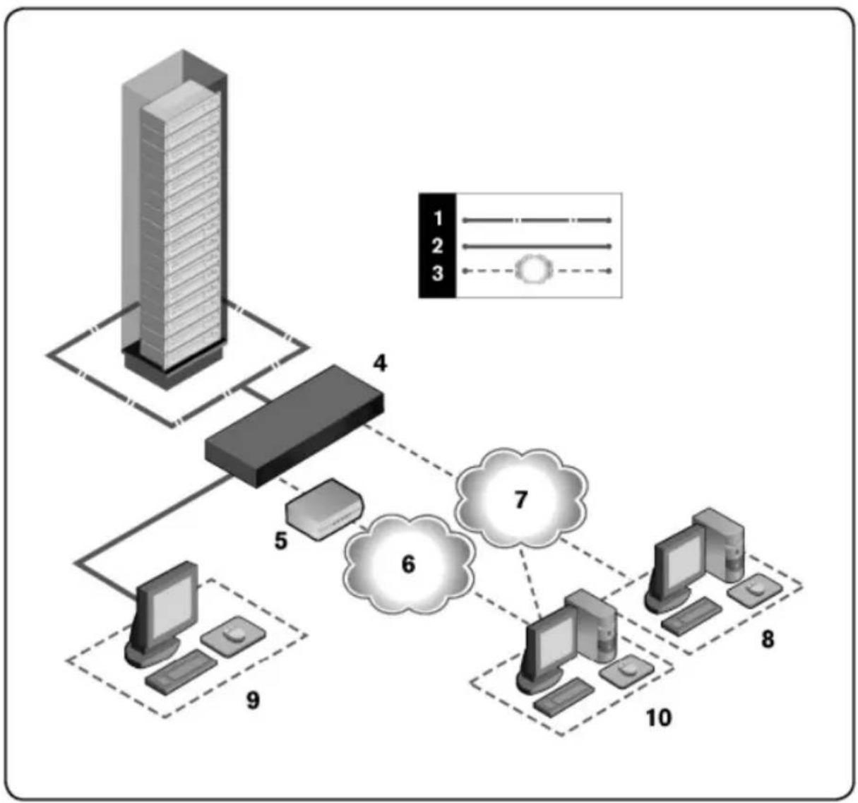
Sample Configuration
Figure 1.1: Example RCS Configuration
flowchart
graph TD
    A["Server"] --> B["Client 4"]
    B --> C["Server 5"]
    C --> D["Cloud 6"]
    D --> E["Server 7"]
    E --> F["Server 8"]
    F --> G["Server 10"]
    style A fill:#f9f,stroke:#333
    style B fill:#ccf,stroke:#333
    style C fill:#cfc,stroke:#333
    style D fill:#fcf,stroke:#333
    style E fill:#cff,stroke:#333
    style F fill:#ffc,stroke:#333
    style G fill:#fcc,stroke:#333
Table 1.1: Descriptions for Figure 1.1
| Number Description Number Description | |
| 1 UTP connection 6 | Telephone network |
| 2 KVM connection to the RCS 7 Ethernet | |
| 3 Remote IP connection 8 | Avocent Management Software Server |
| 4 RCS 9 | Analog User (local UI) |
| 5 Modem 10 | Digital user (computer with Internet browser for a remote OBWI or Dell RCS software) |
Safety Precautions
Use the following safety guidelines to help ensure your own personal safety and to help protect your system and working environment from potential damage.

CAUTION: The power supplies in your system may produce high voltages and energy hazards, which can cause bodily harm. Only trained service technicians are authorized to remove the covers and access any of the components inside th This warning applies to Dell™ Remote Console Switch, Dell™ PowerEdge™ ser and Dell PowerVault™ storage systems.
This document pertains only to the Dell 1082DS/2162DS/4322DS Remote Console Switch. You should also read and follow the additional safety instructions.
• Dell Remote Console Switch User's Guide
- Dell Safety Sheet
• Dell RTF Regulatory Tech Bulletin
General
- Observe and follow service markings.
- Do not service any product except as explained in your system documentation.
- Opening or removing covers that are marked with the triangular symbol with a lightning bolt may expose you to electrical shock.
- Components inside these compartments should be serviced only by a trained service technician.
- This product contains no serviceable components. Do not attempt to open.
If any of the following conditions occur, unplug the product from the electrical outlet and replace the part or contact your trained service provider:
- The power cable, extension cable, or plug is damaged.
- An object has fallen into the product.
- The product has been exposed to water.
- The product has been dropped or damaged.
-
The product does not operate correctly when you follow the operating instructions.
-
Keep your system away from radiators and heat sources. Also, do not block cooling vents.
- Do not spill food or liquids on your system components, and never operate the product in a wet environment. If the system gets wet, see the appropriate section in your troubleshooting guide or contact your trained service provider.
- Use the product only with approved equipment.
- Allow the product to cool before removing covers or touching internal components.
- Operate the product only from the type of external power source indicated on the electrical ratings label. If you are not sure of the type of power required, consult your service provider or local power company.

NOTE: To help avoid damaging your system, be sure the voltage selection switch (if provided) on the power supply is set for the voltage that most closely matches the AC power available in your location. Also be sure that your monitor and attached devices are electrically rated to operate.
- Be sure that your monitor and attached devices are electrically rated to operate with the power available in your location.
- Use only power cables provided with this product.
- To help prevent electric shock, plug the system and peripheral power cable into properly grounded electrical outlets. These cables are equipped with three-prong plugs to help ensure proper grounding. Do not use adaptor p or remove the grounding prong from a cable.
- Observe extension cable and power strip ratings. Make sure that the total ampere rating of all products plugged into the power strip does not exceed 80 percent of the ampere ratings limit for the power strip.
- To help protect your system from sudden, transient increases and decreases in electrical power, use a surge suppressor, line conditioner, or uninterruptible power supply (UPS).
- Position system cables and power cables carefully. Route cables so that the cannot be stepped on or tripped over. Be sure that nothing rests on any cables.
- Do not modify power cables or plugs. Consult a licensed electrician or your power company for site modifications. Always follow your local/national wiring rules.
LAN Options
- Do not connect or use during a lightning storm. There may be a risk of electrical shock from lightning.
- Never connect or use in a wet environment.
Installation
The RCS transmits KVM and serial information between operators and target devices connected to the switch over a network using either an Ethernet or modem connection. The RCS uses TCP/IP for communication over Ethernet. For the best system performance, use a dedicated, switched 100BaseT or 1000BaseT network. You can also use 10BaseT Ethernet.
The RCS uses the Point-to-Point Protocol (PPP) for communication over a V.34, V.90, or V.92 modem. You can perform KVM and serial switching ta using the OBWI or the Avocent management software. For more information the Avocent management software, visit http://www.avocent.com.
The RCS box includes the RCS, RCS software, and the OBWI. You may to use either the RCS software or the OBWI to manage your system. The OBWI manages a single RCS and its connections, while the RCS software manage multiple switches and their connections. If you plan to use only t OBWI, you do not need to install the RCS software.

NOTE: The RCS software can be used to manage some switches. For more information, please refer to the appropriate installer/user guide for your product.

NOTE: Please ensure that all your RCSs have been upgraded to their most recent version of Firmware. For information on upgrading an RCS through the OBWI, refer to "RCS Tools" on page 52.
RCS Quick Setup
The following is a quick setup list. To begin by mounting the RCS in a for detailed installation instructions, see "Getting Started" on page 15.
1 Adjust mouse acceleration on each server to Slow or None.
2 Install the RCS hardware, and connect a Server Interface Pod (SIP) or Avocent® IQ module to each server or tiered switch. Connect each SIP Avocent IQ module to the RCS with CAT 5 cabling and connect the keyboard, monitor, and mouse connectors to the analog port of the RCS.
3 Connect the local port peripherals to the appropriate ports on the back panel of the RCS and set up the network configuration. The IP address be set here or from the RCS software. Dell recommends using a static address for ease of configuration.
4 Using the local port, input all server names using the OBWI interface.
To set up the RCS software (see the RCS Software User's Guide):
1 Install the RCS software on each client workstation.
2 From one client workstation, launch the RCS software.
3 Click the New RCS task button to add the new switch to the RCS software database. If you configured the IP address as described above, select Yes, the product already has an IP address, otherwise select No, the product not have an IP address.
RCS software will find the RCS and all SIPs connected to it and display t names in the Explorer.

NOTE: In addition to adding and managing Dell RCSs using the RCS software, you can add and manage some Avocent switches.
4 Set properties and group servers as desired into locations, sites, or folders through the Explorer.
5 Create user accounts through the OBWI. See "Setting Up User Accounts" on page 77 for more information.
6 Once one client workstation is set up, select File - Database - Save to save a copy of the database with all the settings.
7 From the second client workstation, click File - Database - Load and browse to find the file you have saved. Select the file and click Load.
8 If the local user adds, deletes, or renames any SIPs after you have loa file, you can resynchronize your local switch by selecting the RCS and clicking Resync. To control a connected server, select it in the Explore click the Connect Video task button to launch a server session in the Viewer.
9 Adjust the resolution (select View - Scaling) and quality (select View - Color) of the server video in the Viewer.
Getting Started
The following items are supplied with the Remote Console Switch. Before installing your RCS, locate the necessary items for proper installation.
- Remote Console Switch
- Jumper Cord(s)
• 0U Mounting Bracket - 1U Mounting Bracket Hardware Kit (two additional rails that are pre-mounted to the RCS are included in the kit assembly)
- Cable and Adaptors for SETUP and MODEM
- Remote Console Switch System User's Guide on CD
- Dell Safety Sheet
• Dell RTF Regulatory Tech Bulletin
Additional Items Needed:
• One Dell SIP or Avocent IQ module per attached device
• One CAT 5 patch cable per attached device (up to 45 meters)
Optional Items:
• V.34, V.90, Or V.92-compatible Modem and cables
• Power Control Device(s)
• Port Expansion Module (PEM)

NOTE: You cannot open a virtual media session or a CAC session if the server is connected via a PEM.
Setting up Your Network
The switch uses IP addresses to uniquely identify the switch and the target devices. The RCS supports both Dynamic Host Configuration Protocol (DHCP) and static IP addressing. Make sure that an IP address is reserved each switch and that each IP address remains static while the switch is connected to the network.
Keyboards
A USB keyboard and mouse may be connected to the analog port of the I

NOTE: The RCS also supports the use of multiple keyboards and multiple mice on the analog port. The use of more than one input device simultaneously, however, may produce unpredictable results.
Rack Mounting the RCS
You may either place the RCS on the rack shelf or mount the switch direct into a 19" wide, EIA-310-E compliant rack (four-post, two-post, or threaded methods). The Dell ReadyRails™ system is provided for 1U front-rack, 1U rear-rack, and two-post installations. The ReadyRails system includes two separately packaged rail assemblies and two rails that are shipped attached to the sides of the RCS. In addition, one mounting bracket is provided for 0U configurations and one blanking panel is provided for rear-rack installations.

WARNING: This is a condensed reference. Read the safety instructions in your Safety, Environmental, and Regulatory Information booklet before you begin.

NOTE: The illustrations in this document are not intended to represent a specific switch.
Rack Mounting Safety Considerations
- Rack Loading: Overloading or uneven loading of racks may result in shelf rack failure, causing damage to equipment and possible personal injury.
Stabilize racks in a permanent location before loading begins. Mount components beginning at the bottom of the rack, then work to the to not exceed your rack load rating.
- Power considerations: Connect only to the power source specified on the unit. When multiple electrical components are installed in a rack, ensure that the total component power ratings do not exceed circuit capability. Overloaded power sources and extension cords present fire and shock hazards.
- Elevated ambient temperature: If installed in a closed rack assembly, the operating temperature of the rack environment may be greater than room ambient. Use care not to exceed the 50^ C maximum ambient temperature of the switch.
- Reduced air flow: Install the equipment in the rack so that the amount airflow required for safe operation of the equipment is not compromised
- Reliable earthing: Maintain reliable earthing of rack-mounted equipment. Pay particular attention to supply connections other than direct connections to the branch circuit (for example, use of power strips).
- Product should not be mounted with the rear panel facing in the down position.
Installing the Dell ReadyRails™ System
The ReadyRails system is provided to easily configure your rack for installation of your RCS. The ReadyRails system can be installed using the 1U tool-let method or one of three possible 1U tooled methods (two-post flush mount post center mount, or four-post threaded).
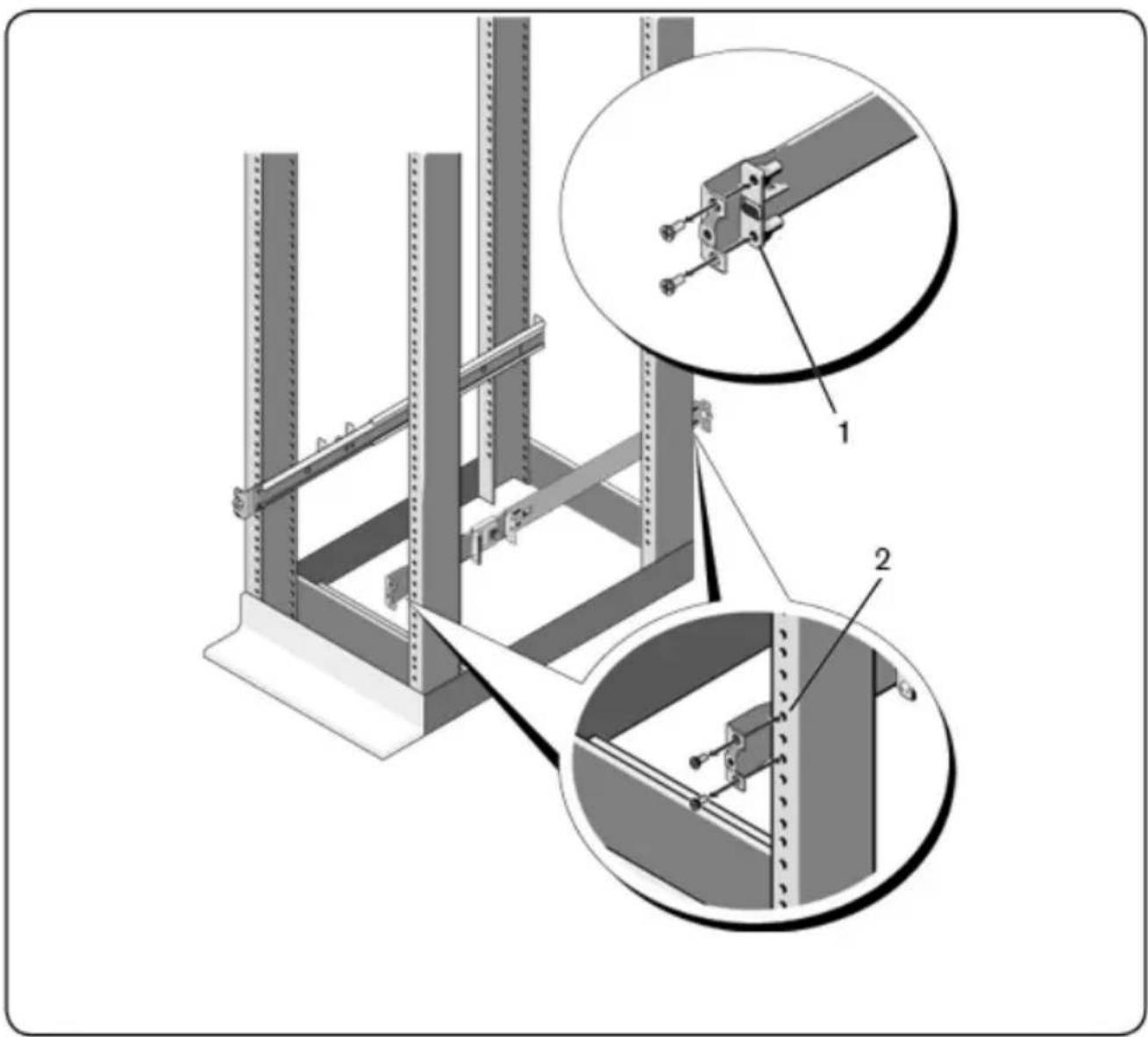
1U Tool-less Configuration (Four-post Square Hole or Unthreaded Round Hole)
1 With the ReadyRails flange ears facing outward, place one rail between left and right vertical posts. Align and seat the rear flange rail pegs in rear vertical post flange. In Figure 2.1, item 1 and its extractions illustrate how the pegs appear in both the square and unthreaded round holes.
Figure 2.1: 1U Tool-less Configuration
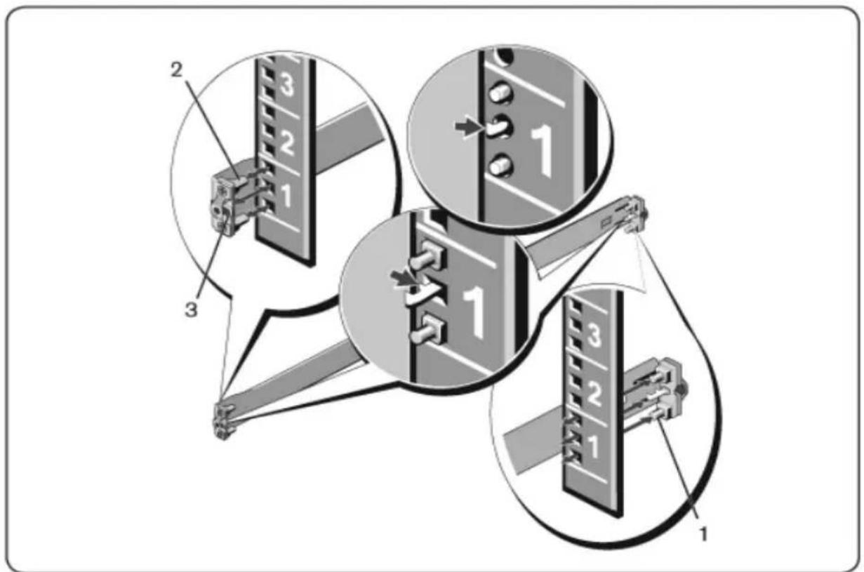
2 Align and seat the front flange pegs in the holes on the front side of vertical post (item 2).
3 Repeat this procedure for the second rail.
4 To remove each rail, pull on the latch release button on each flange ear (item 3) and unseat each rail.
Two-post Flush-mount Configuration
1 For this configuration, the castings must be removed from the front side each ReadyRails assembly (Figure 2.2, item 1). Use a Torx ^™ driver to remove the two screws from each front flange ear (on the device side of rail) and remove each casting. Retain castings for future rack requirements. It is not necessary to remove the rear flange castings.
Figure 2.2: Two-post Flush-mount Configuration
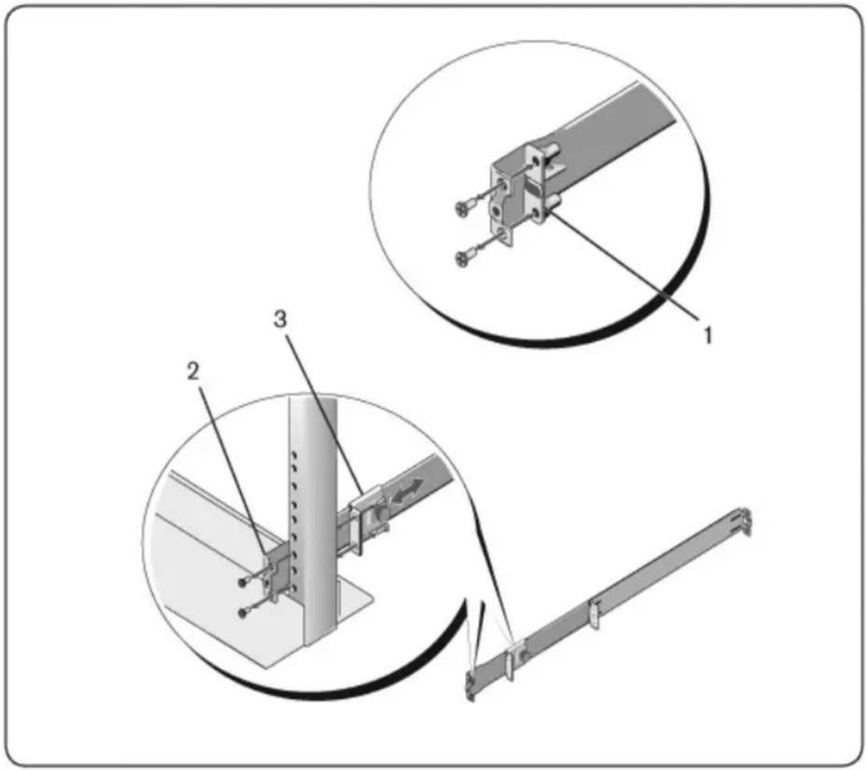
2 Attach one rail to the front post flange with two user-supplied screws 2).
3 Slide the plunger bracket forward against the vertical post and secure the plunger bracket to the post flange with two user-supplied screws (item
4 Repeat this procedure for the second rail.
Two-post Center-mount Configuration
1 Slide the plunger bracket rearward until it clicks into place and secure the bracket to the front post flange with two user-supplied screws (Figure 2.3 item 1).
Figure 2.3: Two-post Center-mount Configuration
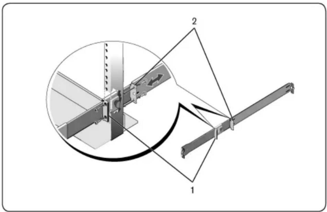
2 Slide the back bracket towards the post and secure it to the post flange two user-supplied screws (item 2).
3 Repeat this procedure for the second rail.
Four-post Threaded Configuration
1 For this configuration, the flange ear castings must be removed from each end of the ReadyRails assemblies. Use a Torx™ driver to remove the two
screws from each flange ear and remove each casting (Figure 2.4, item Retain castings for future rack requirements.
2 For each rail, attach the front and rear flanges to the post flanges with user-supplied screws at each end (item 2).
Figure 2.4: Four-post Threaded Configuration
natural_image
Technical diagram of a structural assembly with two views (1 and 2) showing components like a beam, clamping device, and mounting bracket (no text or symbols present)Installing the RCS
The switch may be mounted in the 1U rear-rack, 1U front-rack, 1U two-post (flush and center), and 0U configurations. The following are examples of 1U rack, 1U front-rack, and 0U configurations. For 1U two-post (flush and center) configurations, you can slide the switch into the rails in the same manner a four-post configurations.
1U Rear-rack Installation
1 Insert the ends of the rails that are attached to the switch into the ReadyRails assembly and push the switch into the rack (Figure 2.5, item
Figure 2.5: 1U Rear-rack Installation
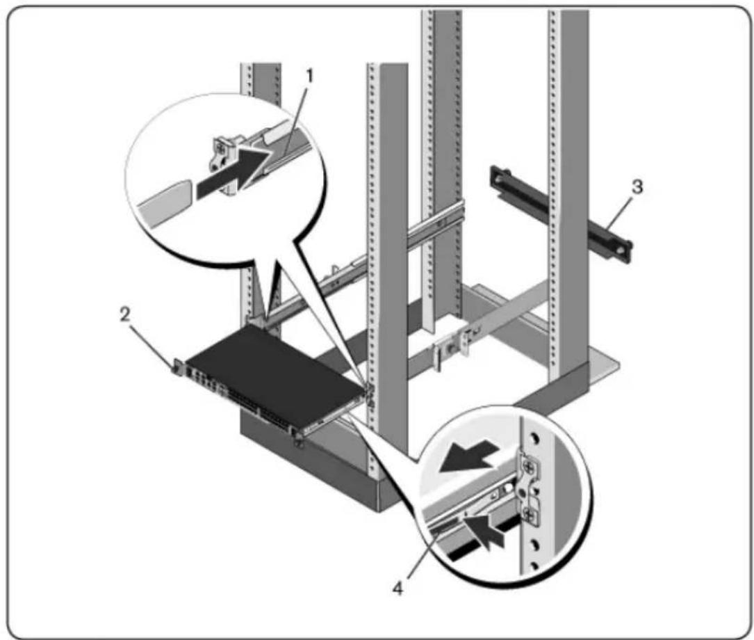
2 Secure each switch rail with the thumbscrew (item 2).
3 (Optional) Assemble the blanking panel to the rails on the front side of rack and tighten the thumbscrews (item 3).
To remove the switch from the rack:
1 Unscrew the thumbscrews and pull the switch assembly out of the rack the travel stops are reached. The travel stop position is intended to put the opportunity to reposition the rail grip; it is not intended for service
2 Locate the blue tabs on the sides of the switch rails (item 4).
3 Push the tabs inward and continue pulling the assembly until the switc rails are clear of the ReadyRails assemblies.
1U Front-rack Installation
Before installation, the rails that are attached to the switch must be re-configured.
1 On each switch rail, lift the tab under the front standoff and slide the forward as you lift the rail from the switch (Figure 2.6, item 1).
Figure 2.6: Rotating the Switch Rails
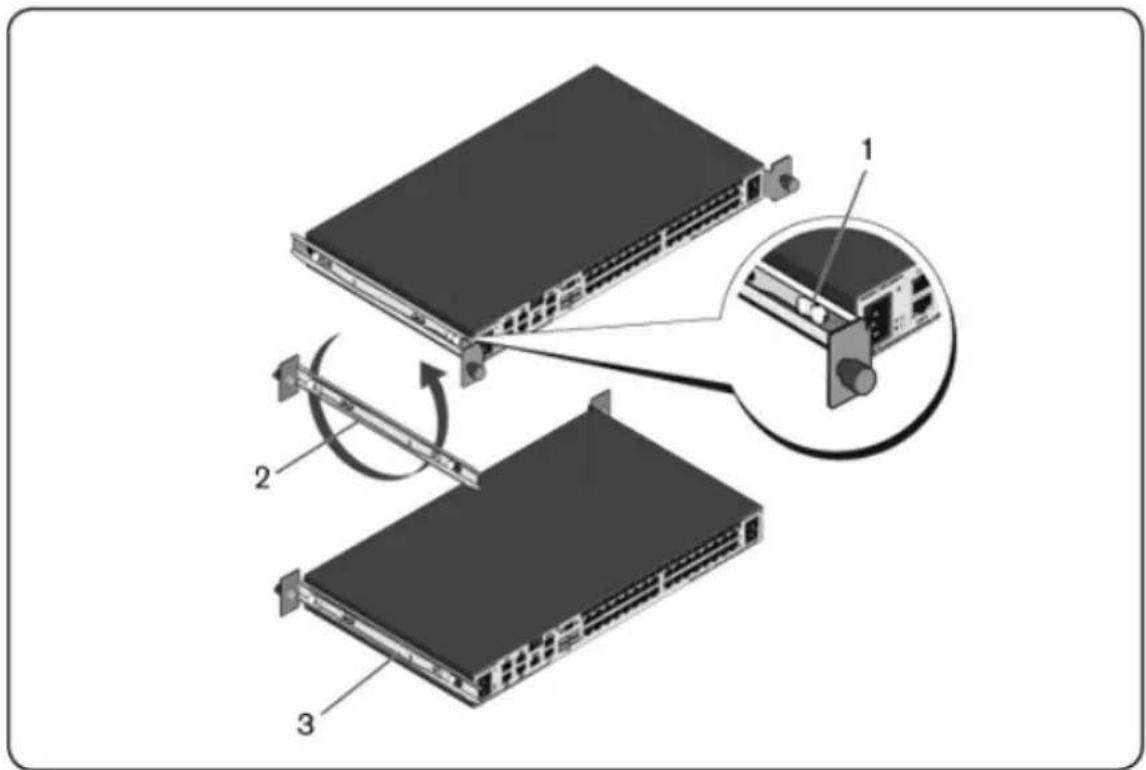
2 Rotate each rail 180^ (item 2) and then reassemble each rail to the swit (item 3).
3 Refer to the 1U rear-rack instructions to insert and remove the switch assembly from the ReadyRails system.

NOTE: No blanking panel is required for this configuration.
0U RCS Installation
1 Align and assemble the 0U mounting bracket to the switch rails (Figure item 1). Tighten the thumbscrews (item 2).
2 Insert the mounting bracket hooks into the rack holes and push down up the blue button pops out and locks the bracket into place.
Figure 2.7: 0U Installation
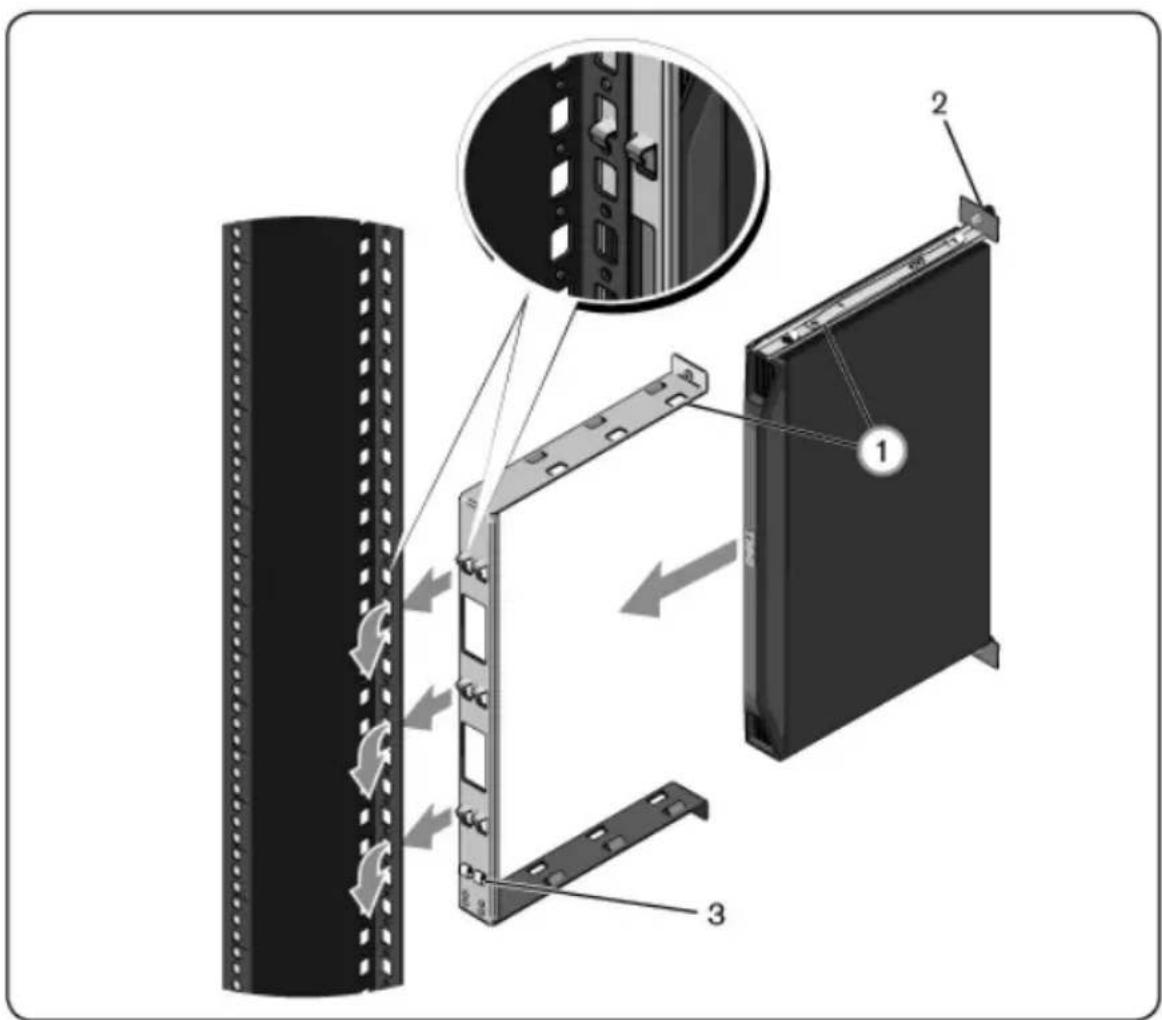
To remove the switch assembly, press the blue button (item 3) to unseat bracket and then lift the assembly from the posts.
Connecting the RCS Hardware
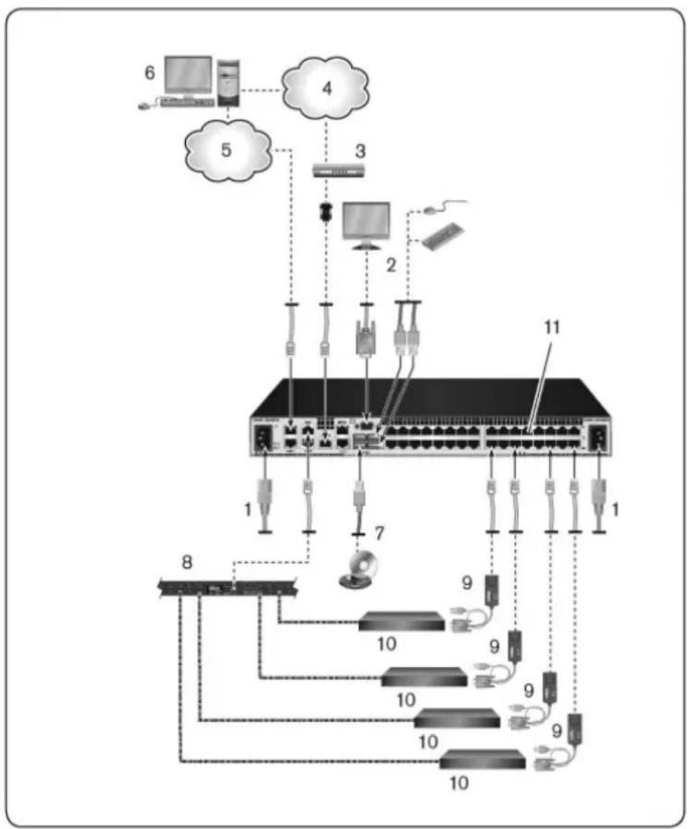
The following diagram illustrates one possible configuration for your RCS hardware.
Figure 2.8: Basic RCS Configuration
flowchart
graph TD
    A["Server 8"] --> B["Switch 10"]
    A --> C["Switch 7"]
    A --> D["Switch 11"]
    B --> E["Router 4"]
    C --> F["Router 3"]
    D --> G["Router 2"]
    E --> H["Computer 6"]
    F --> I["Computer 5"]
    G --> J["Computer 2"]
    H --> K["Cloud 4"]
    I --> L["Cloud 5"]
    J --> M["Cloud 3"]
    K --> N["Cloud 4"]
    L --> O["Cloud 5"]
    M --> P["Cloud 3"]
    N --> Q["Cloud 4"]
    O --> R["Cloud 5"]
    P --> S["Cloud 3"]
    Q --> T["Cloud 4"]
    R --> U["Cloud 5"]
Table 2.1: Basic RCS Configuration Descriptions
| Number Description Number Description | ||
| 1 Jumper cord 7 External virtual media | ||
| 2 Analog user 8 Power control device | ||
| 3 Modem 9 SIPs | ||
| 4 | Telephone network | 10 Target devices |
| 5 Network 11 | RCS (32-port model shown) | |
| 6 Digital user | ||
To connect and turn on your switch:

CAUTION: To reduce the risk of electric shock or damage to your equipn disable the jumper cord grounding plug. The grounding plug is an important feature. Plug the jumper cord into a grounded (earthed) outlet that is easil at all times. Disconnect the power from the unit by unplugging the jumper either the power source or the unit.

NOTE: If the building has 3-phase AV power, ensure that the computer and monitor are on the same phase to avoid potential phase-related video and/or keyboard problems.

NOTE: The maximum supported cable length from switch to device is 30 meters.
- Do not disable the power grounding plug. The grounding plug is an important safety feature.
- Connect the jumper cord into a grounded (earthed) outlet that is accessible at all times.
- Disconnect the power from the product by unplugging the jumper c from either the power source or the product.
- The AC inlet is the main disconnect for removing power to this product. For products that have more than one AC inlet, to remove power completely, all AC line cords must be disconnected.
- This product has no user serviceable parts inside the product enclosure. Do not open or remove product cover.
1 Connect your VGA monitor and USB keyboard and mouse cables to the appropriately labeled ports.
2 Connect one end of a UTP cable (4-pair, up to 150 ft/45 m) to an av numbered port. Connect the other end to an RJ-45 connector of a SIP.
3 Connect a SIP to the appropriate port on the back of a target device. Repeat steps 2 and 3 for all target devices you want to connect.

NOTE: When connecting to a Sun Microsystems target device, you must use a multi-sync monitor in the local port to accommodate Sun computers that support both VGA and sync-on-green or composite sync.
4 Connect a user-supplied UTP cable from the Ethernet network to a LAN port on the back of the RCS. Network users will access the RCS through this port. Plugging the redundant LAN ports to separate Ethernet switches provides additional redundancy in the event one Ethernet switch fails.
5 (Optional) The switch may also be accessed using an ITU V.92, V.90, or V.24-compatible modem. Connect one end of an RJ-45 cable to the MODEM port on the switch. Connect the other end to the supplied RJ to DB-9 (male) adaptor, which then connects to the appropriate port on back of the modem.

NOTE: Using a modem connection instead of a LAN connection will limit the performance capability of your switch.
6 (Optional) Connect a supported PDU to the RCS by connecting one end a CAT 5 cable to the PDU1 port on the switch. Connect the other in the PDU. Connect the power cords from the target devices to the PDU. Connect the PDU to a power source. Repeat this procedure for the PDU port to connect a second PDU, if desired.
7 Turn on each target device, then locate the jumper cord(s) that came with the switch. Connect one end to the power socket on the rear of the switch. Connect the other end into an appropriate power source. If using an RC equipped with dual power, use the second jumper cord to connect to the
second power socket on the rear of the RCS, and plug the other end different power source.

NOTE: Plug the redundant power supplies into separate branch circuits to provide additional redundancy in the event one external AC power source should go away.
8 (Optional) Connect the virtual media devices or smart card readers to a of the USB ports on the switch.

NOTE: For all virtual media sessions, you must use a USB2 or USB2+CAC SIP.
Connecting a SIP
To connect a SIP to each server:
1 Locate the SIPs for your RCS.
2 If you are using a PS/2 SIP connection, attach the color-coded ends of SIP cable to the appropriate keyboard, monitor, and mouse ports on the first server you will be connecting to this RCS. If you are using a U connection, attach the plug from the SIP to the USB port on the first user you will be connecting to this RCS.
3 To the RJ-45 connector on the SIP, attach one end of the CAT 5 ca that will run from your SIP to the RCS. See Figure 2.9.
4 Connect the other end of the CAT 5 cable to the desired Avocent R Interface (ARI) port on the back of your RCS.
5 Repeat steps 2-4 for all servers you wish to attach.

NOTE: Power down the RCS before servicing. Always disconnect the jumper cord from the power source.

NOTE: In addition to Dell SIPs, the RCS may also be connected to devices using Avocent IQ modules, including Sun and Serial IQ modules.
Figure 2.9: SIP Connection
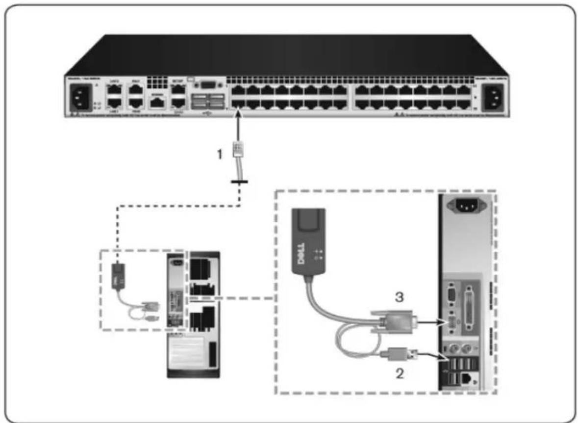
Table 2.2: Descriptions for Figure 2.9
| Number Description |
| 1 CAT 5 |
| 2 USB Connection |
| 3 VGA Connection |
To connect a SIP to a serial device using a UTP connector:
1 Connect the SIP RJ-45 connector to the serial device.
-OT-
Connect the SIP to an RJ-45 to 9-pin female adaptor. Connect the adaptor to the serial port of the serial device.
2 Connect one end of a UTP cable (4-pair, up to 150 ft/45 m) into an available numbered port on the rear of the switch. Connect the other into the RJ-45 connector of the SIP.
3 Connect a USB-to-barrel power cord to the power connector on your SI. Connect the USB connector on the USB-to-barrel power cord into any available USB port on the serial target device.
Adding a Tiered Switch

NOTE: The RCS does not support the EL80-DT.
NOTE: The M1000e Modular Enclosure is supported in a tiered configuration. Attach one end of a CAT5 cable to target port on RCS switch. Attach the other end to the Analog Console Interface (ACI) compatible RJ45 port on the iKVM module on the back of the M1000e chassis. Firmware upgrades to the components of the M1000e Modular Enclosure are not possible via this tiered configuration.
You can tier up to two levels of switches, enabling users to connect to 1024 servers. In a tiered system, each target port on the main switch will connect to the ACI port on each tiered switch. Each tiered switch can be connected to a device with a SIP or Avocent IQ module.
To tier multiple switches:
1 Attach one end of a UTP cable to a target port on the switch.
2 Connect the other end of the UTP cable to the ACI port on the bayour tiered switch.
3 Connect the devices to your tiered switch.
4 Repeat these steps for all the tiered switches you wish to attach to your system.

NOTE: The system will automatically “merge” the two switches. All switches connected to the tiered switch will display on the main switch list in the local UI.

NOTE: The switch supports one tiered switch per target port of the main switch. You cannot attach a switch to the tiered switch.

NOTE: When cascading with an RCS, an 8-port or 16-port analog console switch is not supported as the primary unit in a tiered configuration. The RCS must be the primary unit.
Figure 2.10: Tiering the RCS With a UTP Analog Switch
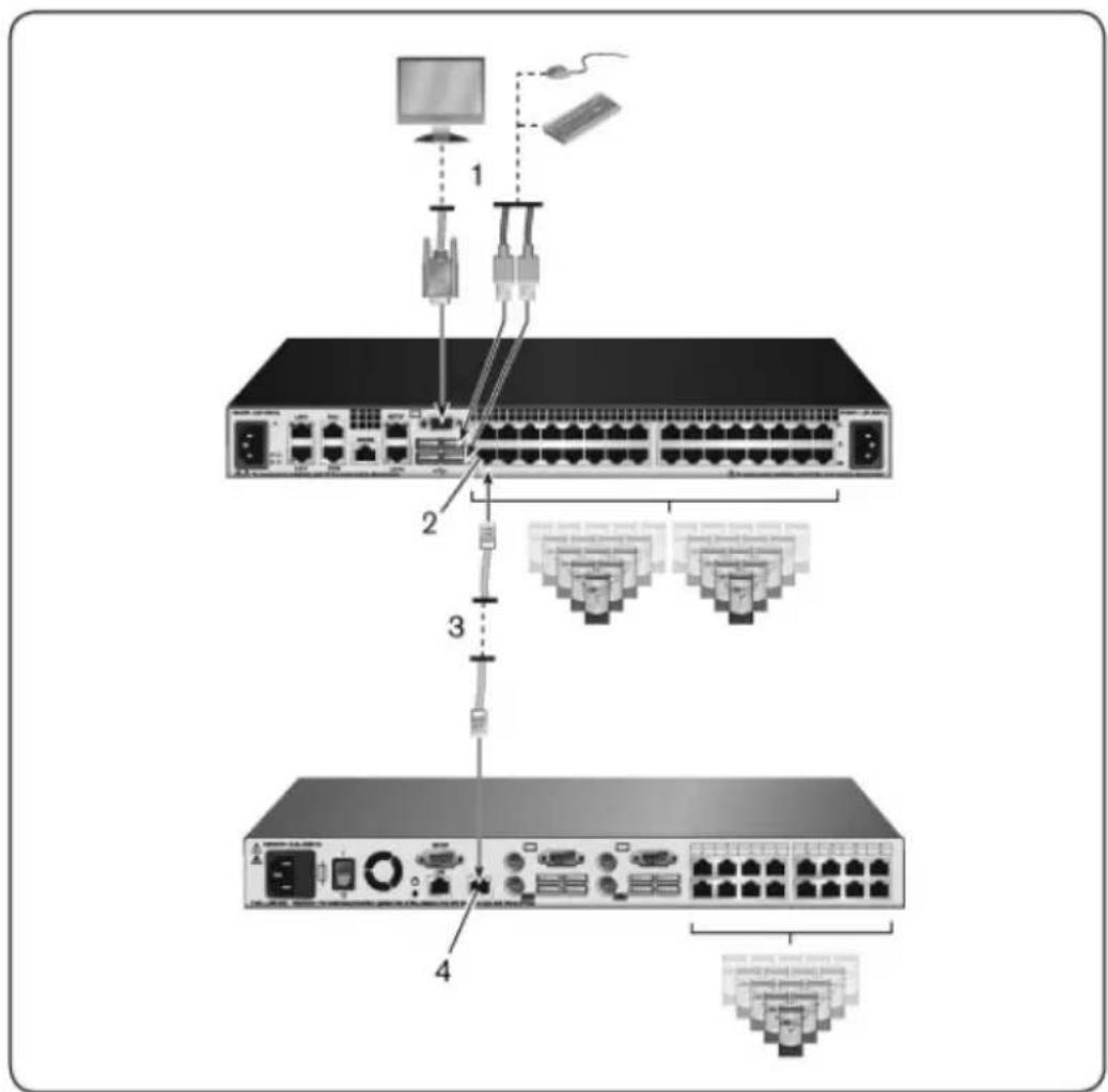
Table 2.3: Descriptions for Figure 2.10
| Number Description |
| 1 Local User |
| 2 ARI Connection |
| 3 UTP Connection |
| 4 ACI Connection |
Cascading with Legacy Switches
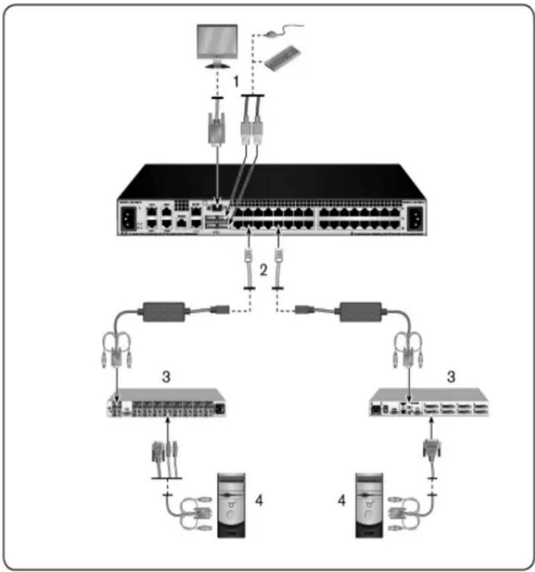
To add a legacy switch (optional):
1 Mount the switch into your rack. Locate a UTP cable to connect your I to the legacy switch.
2 Attach one end of the UTP cabling to the ARI port on the Console Sv
3 Connect the other end of the UTP cable to a PS/2 SIP.
4 Connect the SIP to your legacy switch according to the switch manufacturer's recommendations.
5 Repeat steps 1-4 for all the legacy switches you wish to attach to your switch.

NOTE: The RCS supports only one switch per ARI port. You cannot cascade another switch under this first switch.

NOTE: When cascading with an RCS, an 8-port or 16-port analog console switch is not supported as the primary unit. The RCS must be the primary unit.
Figure 2.11: Cascading Legacy Switches
flowchart
graph TD
    A["Server"] -->|1| B["Switch 1"]
    B --> C["Switch 2"]
    C --> D["Switch 3"]
    D --> E["Switch 4"]
    E --> F["Switch 3"]
    F --> G["Switch 4"]
    G --> H["Switch 3"]
    H --> I["Switch 4"]
    I --> J["Switch 3"]
    J --> K["Switch 4"]
    K --> L["Switch 3"]
    L --> M["Switch 4"]
    M --> N["Switch 3"]
    N --> O["Switch 4"]
    O --> P["Switch 3"]
    P --> Q["Switch 4"]
    Q --> R["Switch 3"]
    R --> S["Switch 4"]
    S --> T["Switch 3"]
    T --> U["Switch 4"]
    U --> V["Switch 3"]
    V --> W["Switch 4"]
    W --> X["Switch 3"]
    X --> Y["Switch 4"]
    Y --> Z["Switch 3"]
Table 2.4: Descriptions for Figure 2.11
| Number Description |
| 1 Local User |
| 2 ARI Connection |
Number Description
3 PS2 Connection
4 Target Connection
Adding a PEM (Optional)
A Port Expansion Module (PEM) allows you to expand each ARI port to accommodate up to eight devices instead of one. See the following figure an figure description table.

NOTE: The PEM operates passively. Therefore, once a user accesses a device attached to a PEM, any subsequent users attempting to access any of the devices attached to that PEM will be blocked.

NOTE: The use of VM or CAC SIPs behind a PEM is not supported.
NOTE: True Serial SIP does not work behind PEM.
To add a PEM (optional):
1 Mount the PEM into your rack. Using up to nine UTP cables, one con your RCS to the PEM, and the other eight connect the PEM to the S attached to each device.
2 Attach one end of the UTP cabling that will run between your PEM an RCS to the RJ-45 connector slightly separated from the other connectors the PEM. Connect the remaining end of the UTP cable to the desired port on the back of your RCS.
3 To one of the eight RJ-45 connectors grouped on the back of the PEM, attach the UTP cabling that will run between your PEM and each device SIP.
4 Connect the other end of the UTP cable to the first SIP.
5 Repeat steps 3-4 for all devices you wish to attach.
Figure 2.12: RCS Configuration With a PEM
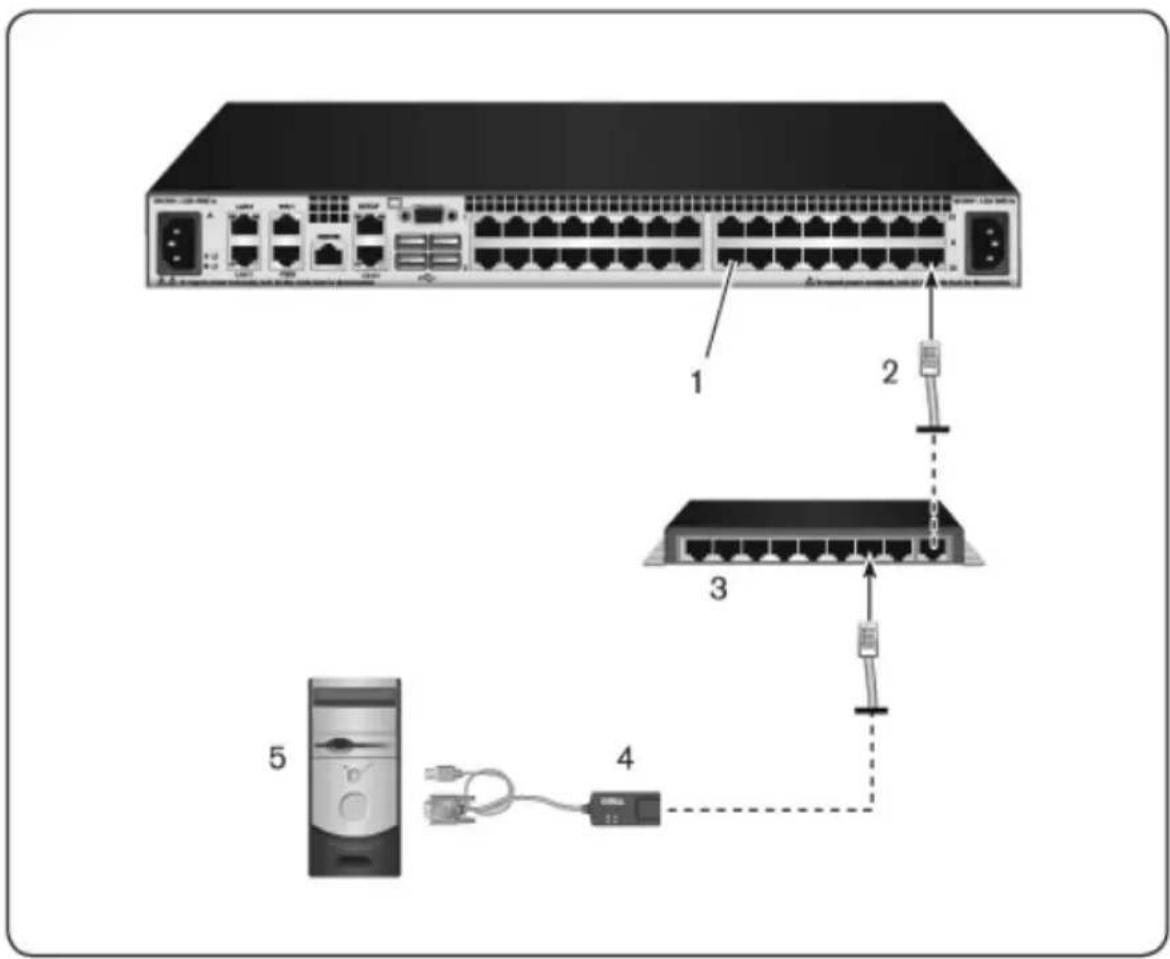
Table 2.5: Descriptions for Figure 2.12
| Number Description |
| 1 ARI Port |
| 2 UTP |
| 3 PEM |
| 4 SIP or Avocent IQ Module |
| 5 Server |
Configuring the Remote Console Switch
Once all physical connections have been made, you will need to configure the switch for use in the overall switch system. This can be accomplished in two ways.
To configure the switch using Avocent management software, see the applicable Avocent Installer/User Guide for detailed instructions.
To configure the switch using the local UI:
See "Network Settings" on page 55 for detailed instructions on using the local to configure initial network setup.
Setting up the Built-in Web Server
You can access the switch using the embedded web server that handles most day-to-day switch tasks. Before using the web server to access the switch, first specify an IP address through the SETUP port on the back panel of the sv or local UI. See Chapter 3 for detailed instructions on using the switch use interface.
Connecting to the OBWI Through a Firewall
For switch installations that use the OBWI for access, the following ports m be opened in a firewall if outside access is desired.
Table 2.6: OBWI Ports With a Firewall
| Port Number | Function |
| TCP 22 | Used for SSH for serial sessions to a SIP. |
| TCP 23 | Used for Telnet (when Telnet is enabled). |
| TCP 80 | Used for the initial downloading of the Video Viewer. The RCS Admin can change this value. |
| TCP 443 | Used by the web browser interface for managing the switch and launching KVM sessions. The RCS Admin can change this value. |
| TCP 2068 | Transmission of KVM session data (mouse & keyboard) or transmission of video on switches. |
| TCP/UDP 3211 | Discovery. |
| TCP 389 | (Optional) Used by LDAP Directory Services; standard access port |
| TCP 636 | (Optional) Used by LDAP Directory Services; Secure/SSL port |
| TCP 3268 | (Optional) Used by Microsoft Active Directory Services; standard access port |
| TCP 3269 | (Optional) Used by Microsoft Active Directory Services; Secure/SSL access port |
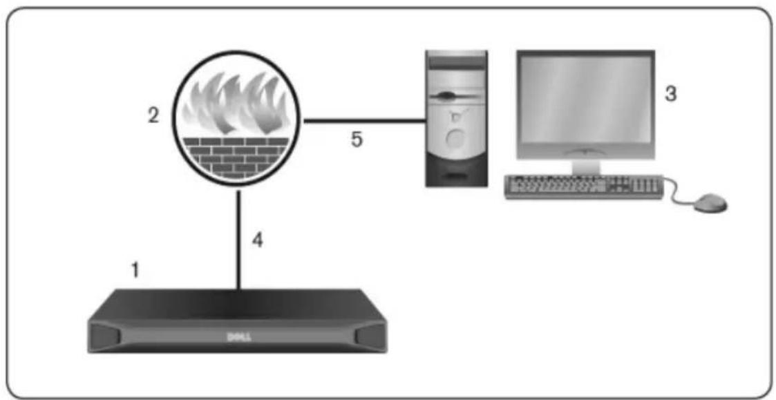
The following figure and table provide a typical configuration, where the u-computer is located outside of the firewall and the switch resides inside the firewall.
Figure 2.13: Typical RCS Firewall Configuration
flowchart
graph TD
    1["Router"] --> 2["Reception Box with Flame"]
    2 --> 4["Server"]
    4 --> 5["Computer"]
    5 --> 3["Desktop"]
Table 2.7: Descriptions for Figure 2.13
| Number Description | |
| 1 RCS | |
| 2 Firewall | |
| 3 User's computer | |
| 4 | Firewall forwards HTTP requests and KVM traffic to the switch |
| 5 User browses to firewall's external IP address | |
To configure the firewall:
To access the switch from outside a firewall, configure your firewall to forwa ports 22, 23 (if telnet is enabled), 80, 443, 2068, and 3211 from its extern interface to the KVM switch through the firewall's internal interface. Consult the manual for your firewall for specific port forwarding instructions.

NOTE: Ports 80 and 443 can be reconfigured by an administrator.
For information on launching the OBWI, see "OBWI" on page 45.
Verifying the Connections
Rear Panel Ethernet Connection LEDs
On the RCS, the rear panel features two LEDs indicating the Ethernet L connection status and two LEDs indicating the Ethernet LAN2 connection status.
- The green LEDs illuminate when a valid connection to the network is established and blink when there is activity on the port.
- The bi-color LEDs may illuminate either green or amber.
• They illuminate green when the communication speed is 1000M.
• They illuminate amber when the communication speed is 100M.
• They are not illuminated when the communication speed is 10M.
Rear Panel Power Status LEDs
The rear panel of each RCS has one for each power supply. There are the LEDs for dual power models (16-port and 32-port) and only one LED for port model. The LED(s) illuminate green when the switch is turned on an operating normally.
- The LED is off if the power supply does not have power or has failed
- The LED illuminates when the unit is ready.
- The LED blinks when the switch is booting or an upgrade is in progr
- The LED blinks "SOS" if a fault condition occurs, such as power supp failure, elevated ambient temperature, or fan failure. The LED will cont to blink "SOS" as long as the failure persists.
The switch prevents a serial break from the attached device if the module power. However, a user can generate a serial break with the attached device pressing Serial Break on the serial session viewer.
Adjusting Mouse Settings on Target Devices
Before a computer connected to the switch can be used for remote user co: you must set the target mouse speed and turn off acceleration. For machine running Microsoft® Windows® (Windows NT®, 2000, XP, Server 2003), use the default PS/2 mouse driver.
To ensure that the local mouse movement and remote cursor display remain sync, mouse acceleration must be set to “none” for all user accounts accessing remote system through a KVM switch. Mouse acceleration must also be set “none” on every remote system. Special cursors should not be used and curs visibility options, such as pointer trails, Ctrl key cursor location animations, cursor shadowing, and cursor hiding, should also be turned off.

NOTE: If you are not able to disable mouse acceleration from within a Windows operating system, or if you do not wish to adjust the settings of all your target devices, you may use the Tools - Single Cursor Mode command available in the Video Viewer window. This command places the Video Viewer window into an “invisible mouse” mode, which allows you to manually toggle control between the mouse pointer on the target system being viewed and the mouse pointer on the client computer.
Local and Remote Configuration
The RCS comes equipped with two “point-and-click” interfaces: a local user interface (local UI) and a remote OBWI. Using the configuration options provided by these interfaces, you can tailor the switch to your specific application, control any attached devices, and handle all basic KVM or serial switch needs.

NOTE: The local UI and remote OBWI are almost identical. Unless specified, all information in this chapter applies to both interfaces.
From either interface, you can launch two different kinds of sessions:
- The Video Viewer window allows you to control the keyboard, monitor, mouse functions of individual target devices connected to the switch in time. You may also use predefined global macros to perform actions with the Video Viewer window. For instructions on how to use the Video Viewer, see Chapter 4.
- The serial viewer window allows you to manage individual serial target devices either by using commands or scripts.
Local User Interface (UI)
The switch includes a local port on the back. This port enables you to use a keyboard, monitor and mouse directly to the switch and use the local UI.
You can choose any of the following keystrokes to be configured to open local UI or to switch between the local UI and an active session: <Print
Screen>,
To launch the local UI:
1 Connect your monitor, keyboard and mouse cables to the switch. For more information, see "Connecting the RCS Hardware" on page 25.
2 Press any of the enabled keystrokes to launch the local UI.
3 If local UI authentication has been enabled, enter your username and password.

NOTE: If the switch has been added to an Avocent management software server, then the Avocent management software server will be accessed to authenticate the user. If the switch has not been added to an Avocent management software server, or if the Avocent management software server cannot be reached, then the switch local user database will be accessed to authenticate the user. The default local username is Admin, and there is no password. Usernames in the local user database are case-sensitive.
Attached target devices in the Local Port User Interface can be viewed and managed from two individual screens that are selected from the left navigation toolbar. For less than 20 targets, the Target List-Basic screen is recommended for navigation. For more than 20 attached target devices, the Target List-Full screen provides additional navigation tools. At the Target List-Full screen you can navigate by entering the page number, using the page navigation buttons using the filter. Either the Basic or Full screens can be set as the default for selecting target devices.
Filtering
You may filter the list of target devices by providing a text string that will be used to retrieve matching items. Filtering can provide a shorter, more exact of items. When filtering is performed, the Name column is searched for the specified text string. The search is not case sensitive. When filtering, you may use an asterisk (*) before or after text strings as a wildcard. For example, emailserver* and clicking Filter will display items with emailserver at the beginning (such as emailserver, emailserverbackup).
OBWI
The switch OBWI is a remote, web browser based user interface. For details setting up your system, see "Connecting the RCS Hardware" on page 25. Following table lists the operating systems and browsers that are supported by the OBWI. Make sure that you are using the latest version of your Web
Table 3.1: Operating Systems Supported by the OBWI
| Operating System | Browser | |
| Microsoft®Internet Explorer version 6.0 SP1 and later | Firefox version 2.0 and later | |
| Microsoft Windows 2000 Workstation or Server with Service Pack 2 | Yes Yes | |
| Microsoft Windows Server® 2003 Standard, Enterprise, or Web Edition | Yes Yes | |
| Microsoft Windows Server® 2008 Standard, Enterprise, or Web Edition | Yes Yes | |
| Windows XP Professional with Service Pack 3 | Yes Yes | |
| Windows Vista® Business with Service Pack 1 | Yes Yes | |
| Red Hat Enterprise Linux®4 and 5 Standard, Enterprise or Web Edition (Smart card may not be supported by the operating system) | No Yes | |
| Sun Solaris®9 and 10 (Smart card may not be supported by the operating system) | No Yes | |
| Novell SUSE Linux Enterprise 10 and 11 (Smart card may not be supported by the operating system) | ||
| Ubuntu 8 Workstation (Smart card may not be supported by the operating system) | No Yes | |
To log in to the switch OBWI:
1 Launch a web browser.
2 In the address field of the browser, enter the IP address or host name assigned to the switch you wish to access. Use https://xxx.xx.xx.xx or https://hostname as the format.

NOTE: If using IPv6 mode, you must include square brackets around the IP address. Use https://[<ipaddress-] as the format.
3 When the browser makes contact with the switch, enter your username password, then click Login. The switch OBWI will appear.

NOTE: The default username is Admin with no password.
To log in to the switch OBWI from outside a firewall, repeat the above procedure, entering the external IP address of the firewall instead.

NOTE: The RCS will attempt to detect if Java is already installed on your PC. If it is not, in order to use the on-board web interface, you will need to install You may also need to associate the JNLP file with Java WebStart.

NOTE: Using the on-board web interface requires using Java Runtime Environment (JRE) version 1.6.0_11 or higher.

NOTE: Once you have logged in to the on-board web interface, you will not have to log in again when launching new sessions unless you have logged out or your session has exceeded the inactivity timeout specified by the administrator.
Using the User Interfaces
After you have been authenticated, the user interface appears. You may vie access, and manage your switch, as well as specify system settings and cha profile settings. The following figure shows the user interface window areas. Screen descriptions are provided in the following table.
Figure 3.1: User Interface Window
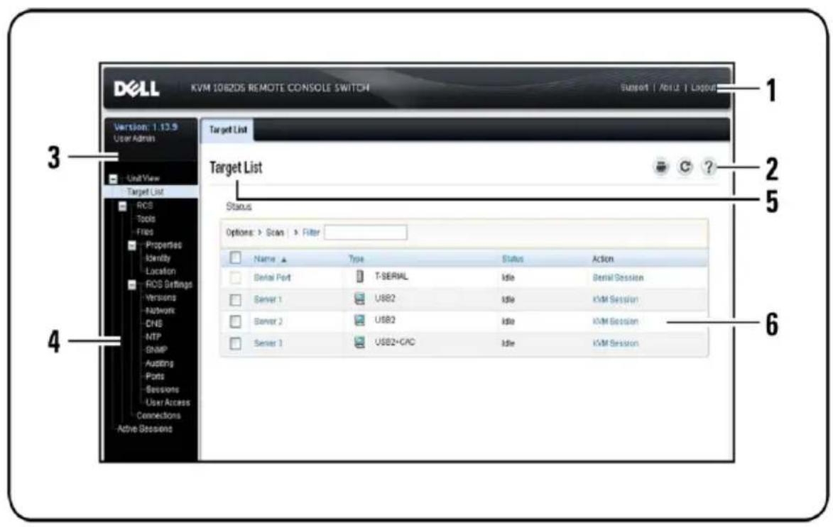
Table 3.2: User Interface Descriptions
Number Description
| 1 | Top option bar: Use the top option bar to contact Technical Support, view the software general information, or log out of an OBWI session. |
| 2 | Second option bar: Use this bar to print a web page, refresh the current web page or access the Help tool. |
| 3 | Version block: The firmware version of the product and the username of the user currently logged in appears on the left side of the top option bar. |
Number Description
| 4 | Side navigation bar: Use the side navigation bar to select the information to be displayed. You can use the side navigation bar to display windows in which you can specify settings or perform operations. |
| 5 | Navigation tabs: The selected tab displays the system information in the content area. Some tabs provide sub tabs that can be clicked to display and revise details within a category. |
| 6 | Content area: Use the content area to display or make changes to the switch OBWI system. |
Launching a Session

NOTE: Java 1.6.0_11 or later is required to launch a session.
To launch a session:
1 From the side navigation bar, select Target List. A list of available devices will appear.
2 The applicable action, KVM Session or Serial Session, will be displayed the Action column, and will depend on the target device that was selected to launch the session. If more than one action is available for a given device, click the drop-down arrow and select the applicable action from list.
If the target device is currently in use, you may be able to gain access a connection to the device if your preemption level is equal to or higher the current user's.
The RCS also allows serial sessions to Serial SIPs via an external Telnet application such as PuTTY. Telnet and SSII sessions are only used to con Serial SIPs and cannot be used to access or manage RCS or KVM target To launch a serial session from a Telnet or SSH application:
1 Enter the RCS host IP address that the Serial SIP is connected to.
2 Enter
3 Enter the password for the RCS user.

NOTE: The Telnet feature default is disabled. To enable Telnet support, refer to "Configuring Serial Sessions" on page 77.
To switch to the active session from the local UI (local users only):
1 From the side navigation bar, select Local Session.
2 Select the Resume Active Session checkbox. The Video Viewer window will appear.
Scan Mode
In Scan mode, the switch scans multiple target devices. The scanning order determined by placement of the target device in the list. You can also conf the amount of time before the scan moves to the next target device in the sequence.

NOTE: The Scan button is disabled if you are connected via modem.
To add target devices to the Scan list:
1 From the side navigation bar, select Unit View - Target List to open the Target Devices screen.
2 Select the checkboxes next to the names of the target devices you wish scan.
3 Click Scan.
To configure Scan Time:
1 From the side navigation bar, select Ports - Local Port UI to open the Local Port UI Settings screen.
2 Under the Scan Mode heading, enter an amount of time in seconds (from 255) in the Scan Time field.
3 Click Save.
Viewing System Information
You can view switch and target device information from the following screen the user interface.
Table 3.3: System Information
| Category Select This: To View This: | ||
| RCS | Unit View - RCS - Tools | RCS name and type, and the RCS tools (Maintenance, Diagnostics, Certificates and Trap MIB) |
| Unit View - RCS - Files | RCS Configuration, User Database, and Target Device | |
| Unit View - RCS - Properties - Identity | Part Number, Serial Number, and EID | |
| Unit View - RCS - Properties - Location | Site, Department, and Location | |
| Unit View - RCS Settings - Versions | Current Application and Boot versions | |
| Target Device | Unit View - Target List | List of connected target devices, as well as the Name, Type, Status, and Action of each deviceClick on a target device to view the following additional information: Name, Type, EID, available session option, and the connection path |
RCS Tools
From the Tools - Maintenance - Overview screen, you can view the appliance name and type. You can also perform basic appliance tasks.
Rebooting the RCS
To reboot the RCS:
1 From the side navigation bar, select the Unit View - RCS - Tools - Maintenance - Overview tab to open the Unit Maintenance screen.
2 Click Reboot.
3 A dialog box appears, warning you that all active sessions will be disconnected. Click OK.

NOTE: If you are using the local UI, the screen will be blank while the switch reboots. If you are using the remote OBWI, a message will appear to let you know that the interface is waiting on the appliance to complete the reboot.
Upgrading RCS Firmware
You can update your RCS with the latest firmware available.
After the Flash memory is reprogrammed with the upgrade, the switch performs a soft reset, which terminates all SIP sessions. A target device experiencing a firmware update may not display, or may display as disconnected. The target device will appear normally when the Flash update is completed.
Attention: Disconnecting a SIP during a firmware update or cycling power to the target device will render the module inoperable and require the SIP to returned to the factory for repair.
To upgrade the switch firmware:
1 From the side navigation bar, select the Unit View - RCS - Tools - Maintenance - Upgrade tab to open the Upgrade RCS Firmware window
2 Click Upgrade to open the Upgrade Appliance Firmware.
3 Select one of the following methods from which to load the firmware file: Filesystem, TFTP, FTP, or HTTP.

NOTE: The Filesystem option is only available on the remote OBWI.
4 If you selected Filesystem, select Browse to specify the location of the firmware upgrade file.
-0r-
If you selected TFTP, enter the Server IP Address and Firmware File you wish to load.
-Or-
If you selected FTP or HTTP, enter the Server IP Address and Firmware File you wish to load, as well as the User Name and User Password.
5 Click Upgrade.
Saving and Restoring RCS Configurations and RCS User Databases
You may save the switch configuration to a file. The configuration file will contain information about the managed appliance. You may also save the user database on the switch. After saving either file, you may also restore previously saved configuration file or local user database file to the switch.
To save a managed appliance configuration or user database of a managed appliance:
1 From the side navigation bar, click the Unit View - RCS - Files tab.
2 Click either the RCS Configuration tab or the User Database tab, then click the Save tab.
3 Select the file save method: Filesystem, TFTP, FTP, or HTTP PUT.
4 If you selected TFTP, enter the Server IP Address and Firmware Filena you wish to load.
-Or-
If you selected FTP or IITTP, enter the Server IP Address, Username, User Password, and Firmware Filename you wish to load.
5 Enter an encryption password if you wish to encrypt the data before download.
6 Click Download. The Save As dialog box will open.
7 Navigate to the desired location and enter a name for the file. Click Save.
To restore a managed appliance configuration or user database of a managed appliance:
1 From the side navigation bar, click the Unit View - RCS - Files tab.
2 Click either the RCS Configuration tab or the User Database tab, then click the Restore tab.
3 Select the file save method: Filesystem, TFTP, FTP, or HTTP.
4 If you selected Filesystem, select Browse to specify the location of the firmware upgrade file.
-Or-
If you selected TFTP, enter the Server IP Address and Firmware Filename you wish to load.
-Or-
If you selected FTP or IHTTP, enter the Server IP Address, User Name, User Password, and Firmware Filename you wish to load.
5 Click Browse. Navigate to the desired location and select the file name. Click Upload.
6 Enter the decryption password if the original file was encrypted.
7 After the success screen appears, reboot the managed appliance to enable the restored configuration. See "Rebooting the RCS" on page 52.
To recover from a Flash update failure:
If after a Flash procedure, the RCS does not boot into the new firmware, you may use the following steps to revert to the previous firmware version.
1 Connect a serial cable to the SETUP port on the rear panel of the l
2 Run a terminal program on the PC connected to the Setup port. The port settings should be: 9600 baud, 8 data bits, 1 stop bit, no parity, flow control.
3 Turn on the RCS.
4 In the terminal program, when the prompt "Hit any key to stop autob appears, press any key. A menu will be displayed.
5 Enter <1> (Boot Alternate) and press
6 After the RCS reboots, you can attempt the Flash upgrade.
Network Settings

NOTE: Only switch administrators can make changes to the network dialog box settings. Other users will have view only access.
From the side navigation bar, click Network to display the General, IPv4, IPv6 tabs.
To configure general network settings:
1 Click the Network tab, then click the General tab to display the RCS General Network Settings screen.
2 Select one of the following options from the LAN Speed drop-down me Auto-Detect, 10 Mbps Half Duplex, 10 Mbps Full Duplex, 100 Mbps Half Duplex, 100 Mbps Full Duplex, or 1 Gbps Full Duplex.

NOTE: You must reboot if you change the Ethernet mode.
3 Select either Enabled or Disabled in the ICMP Ping Reply drop-down menu.
4 Verify or modify the HTTP or HTTPS ports. The settings will default HTTP 80 and HTTPS 443.
5 Click Save.
To configure IPv4 network settings:
1 Click the IPv4 tab to display the IPv4 Settings screen.
2 Click to fill or clear the Enable IPv4 checkbox.
3 Enter the desired information in the Address, Subnet, and Gateway fields.
IPv4 addresses are entered as the xxx.xxx.xxx.xxx dot notation.
4 Select either Enabled or Disabled from the DHCP drop-down menu.

NOTE: If you enable DHCP, any information that you enter in the Address, Subnet, and Gateway fields will be ignored.
5 Click Save.
To configure IPv6 network settings:
1 Click the IPv6 tab to display the IPv6 Settings screen.
2 Click to fill or clear the Enable IPv6 checkbox.
3 Enter the desired information in the Address, Subnet, and Prefix Length fields. IPv6 addresses are entered as the FD00:172:12:0:0:0:0:33 or abbreviated FD00:172:12::33 hex notation.
4 Select either Enabled or Disabled from the DIICP drop-down menu

NOTE: If you enable DHCPv6, any information that you enter in the Address, Gateway, and Prefix length fields will be ignored.
5 Click Save.
DNS Settings
You can choose to either manually assign the DNS server or to use the ad obtained using DHCP or DHCPv6.
To manually configure DNS settings:
1 From the side navigation bar, select DNS to display the RCS DNS Settings screen.
2 Select Manual, DIHCP (if IPv4 is enabled) or DIHCPv6 (if IPv6 is enabled).
3 If you selected Manual, enter the DNS Server numbers in the Primary, Secondary, and Tertiary fields.
4 Click Save.
NTP Settings
The switch must have access to the current time to verify that certificates not expired. You can configure the switch to request time updates from the NTP. Refer to Configuring the Network Time Protocol (NTP) Settings in Chapter 5.
SNMP Settings
SNMP is a protocol used to communicate management information between network management applications and the switch. Other SNMP managers can communicate with your switch by accessing MIB-II. When you open the S screen, the OBWI will retrieve the SNMP parameters from the unit.
From the SNMP screen, you can enter system information and community strings. You may also designate which stations can manage the switch as I receive SNMP traps from the switch. If you select Enable SNMP, the unit will respond to SNMP requests over UDP port 161.
To configure general SNMP settings:
1 Click SNMP to open the SNMP screen.
2 Click to enable the Enable SNMP checkbox to allow the switch to respond to SNMP requests over UDP port 161.
3 Enter the system's fully qualified domain name in the Name field, as a node contact person in the Contact field.
4 Enter the Read, Write, and Trap community names. These specify the community strings that must be used in SNMP actions. The Read and Write strings only apply to SNMP over UDP port 161 and act as pass
that protect access to the switch. The values can be up to 64 character length. These fields may not be left blank.
5 Type the address of up to four management workstations that are allowed manage this switch in the Allowable Managers fields. Alternatively, you may leave these fields blank to allow any station to manage the RCS.
6 Click Save.
Auditing Event Settings
An event is a notification sent by the switch to a management station indicating that something has occurred that may require further attention.
To enable individual events:
1 Click Auditing to open the Events screen.
2 Specify the events that will generate notifications by clicking the appropriate checkboxes in the list.
-Or-
Select or clear the checkbox next to Event Name to select or deselect the entire list.
3 Click Save.
Setting Event Destinations
You can configure audit events to be sent to SNMP trap destinations and S servers. The events enabled on the Events screen are sent to all the servers on the Event Destination screen.
1 Click Auditing and the Destinations tab to open the Event Destinations screen.
2 Type the address of up to four management workstations to which this switch will send events in the SNMP Trap Destination fields, as well as to four Syslog servers.
3 Click Save.
Ports - Configuring SIPs
From the switch, you can display a list of the attached SIPs, as well as following information about each SIP: EID (electronic ID), Port, Status, Application, Interface Type, and USB Speed. You can click on one of the to view the following additional information: Switch Type, Boot Version, Application Version, Hardware Version, FPGA Version, Version Available, and Upgrade Status.
You can also perform the following tasks: delete offline SIPs, upgrade the firmware, set the USB speed, or decommission the cables.
To delete offline SIPs:
1 From the side navigation bar, click Ports - SIPs to open the SIP screen.
2 Click Delete Offline.
Upgrading SIPs
The SIP Flash upgrade feature allows RCS Administrators to update the SI with the latest firmware available. This update can be performed using the switch user interface or Avocent management software.
After the Flash memory is reprogrammed with the upgrade, the switch per a soft reset, which terminates all SIP sessions. A target device experiencing firmware update may or may not display as disconnected. The target device appear normally when the Flash update is completed.
If the RCS is configured to Auto-Upgrade SIPs, the SIPs will automatically update when the switch is updated. To update your switch firmware, see Tools" on page 52 or the Avocent management software Online Help. If i occur during the normal upgrade process, SIPs may also be force-upgraded needed.

NOTE: Check http://www.dell.com for firmware upgrade files.
To change the SIP Auto-Upgrade feature:
1 From the side navigation bar, click Ports - SIPs to open the SIPs screen.
2 Select the checkbox(es) next to the SIP(s) that you wish to upgrade and click Enable Auto-Upgrade.
Attention: Disconnecting a SIP during a firmware update or cycling power to the target device will render the module inoperable and require the SIP to returned to the factory for repair.
To upgrade the SIP firmware:
1 From the side navigation bar, click Ports - SIPs to open the SIPs screen.
2 Select the checkbox(cs) next to the SIP(s) that you wish to modify.
3 Select Choose an operation and select Upgrade.
4 If the settings are correct, click Upgrade.
To set the USB Speed:

NOTE: This section only applies to the USB2 SIP.
1 From the side navigation bar, click Ports - SIPs to open the SIPs screen.
2 Select the checkbox(es) next to the SIP(s) that you wish to modify.
3 Select Choose an operation and select either Set USB 1.1 Speed or Set USB 2.0 Speed.
Power Device Settings

NOTE: You must have Administrator privileges to change power control device settings.

NOTE: Refer to www.dellkvm.com for a list of supported PDUs.
From the RCS Power Devices screen, you can view a list of connected pow devices, as well as the following information about each power device: Name, Port, Status, Version, Model, Buzzer, Alarm, and Temperature. You can also select a power device, then select Settings to view the following details about
that power device: Name, Description, Status, Version, Sockets, Vendor Name, Model, and Input Feeds.
If a target device is connected to a power control device outlet, you can turn off or cycle (turn off, then turn on) the target device.
To turn on, turn off or power cycle a target device:
1 From the side navigation bar, click Ports - Power Devices to open the Power Devices screen.
2 Click the name of the unit you wish to configure and select Outlet List.
3 Select the checkbox to the left of the outlet(s) that you wish to conf
4 Click On, Off, or Cycle, as desired.
To delete offline power devices:
1 From the side navigation bar, click Ports - Power Devices to open the Power Devices screen.
2 Click Delete Offline.
To change the minimum on time, off time or wake up state:
1 From the side navigation bar, click Ports - Power Devices to open the Power Devices screen.
2 Click the name of the unit you wish to configure and select Outlets.
3 Click the outlet name that you wish to modify.
4 Use the drop-down windows to alter the desired settings and click Save.
Associated Target Servers and Power Outlets
In the OBWI Target List page, power control actions are selectable for a with linked outlets. Selecting the Ports - Power Devices tabs, and then click on a device name will display the Device Settings, Device Firmware Upgrade and Outlet List tabs. Click the Outlet List tab to display the outlets link a target device.
In the following figure, the target device named Server2 has linked power out. Clicking on the drop-down menu arrow in the Action column shows the additional power actions available.
Figure 3.2: Target List
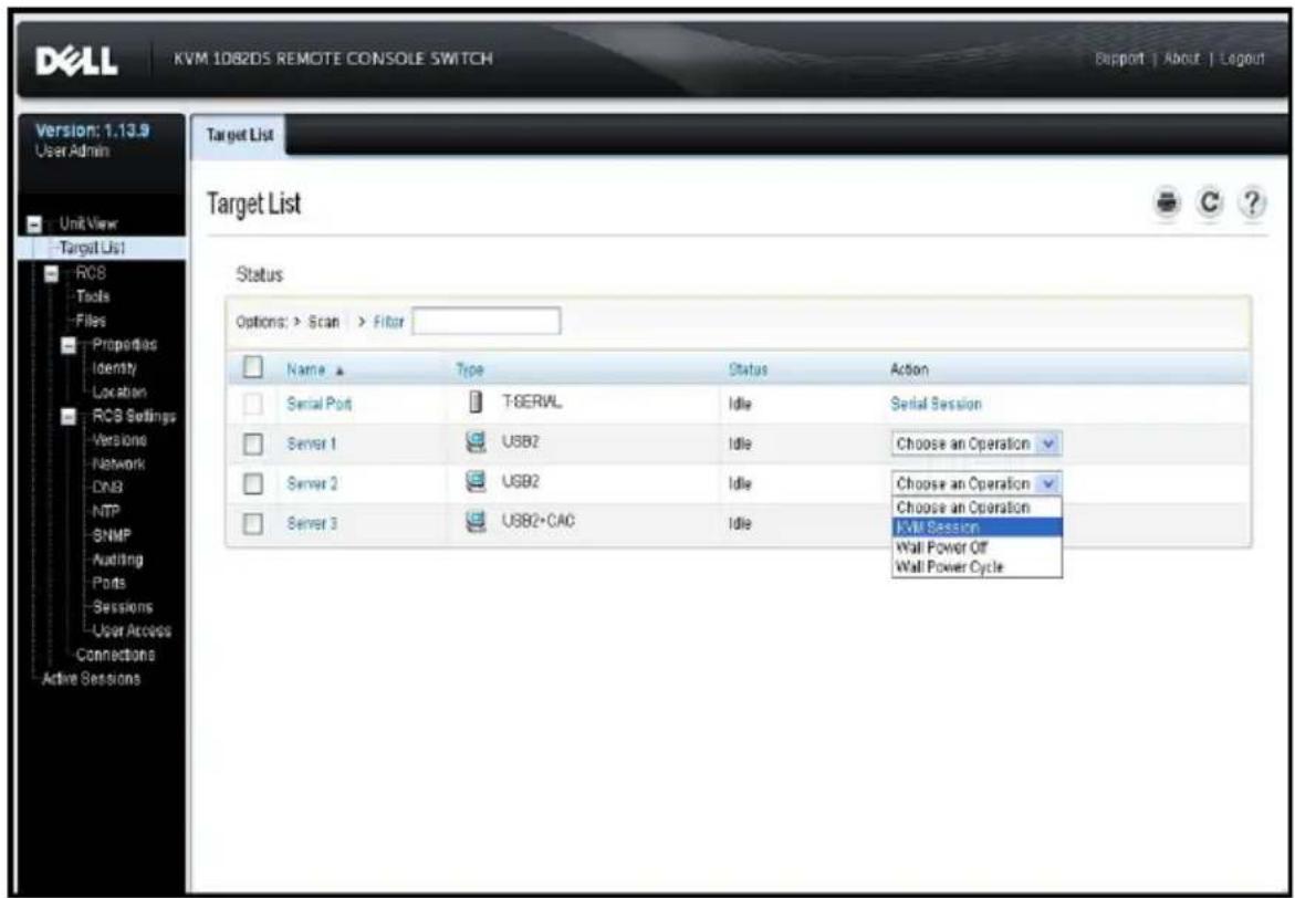
In the following figure, the target Unit Overview page for Server2 shows the Outlet Power, where outlet 1 and outlet 9 from PDU 1 are linked to Serve
Figure 3.3: Target Overview Server2
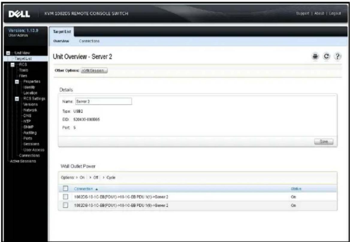
Grouping Power Outlets
The outlets can be linked or associated with the target server for easier c To group outlets (or outlets to servers), the first device to be named mu the Manual name field. The second and subsequent devices must use the to Target Device menu, and then select the target name for the first dev the drop down list.
Power actions performed on the Target List page are applied to all applications. Power control actions for specific power outlets of a target may be performed on the Unit Overview page. In the following figure, the target Group2 is composed of power outlets 4 and 5 from PDU 1.
To group sockets 4 and 5:
1 Select outlet 4 to display the Power Devices Outlet Settings page.
2 Select Manual and enter Group2.
3 Click Save.
4 Select outlet 5 to display the Power Devices Outlet Settings page.
5 Select Link to Target Device, select Group2 from the drop down menu.
6 Click Save. After returning to the Outlet List, outlets 4 and 5 will have the same name.
Figure 3.4: Target Overview for Group2
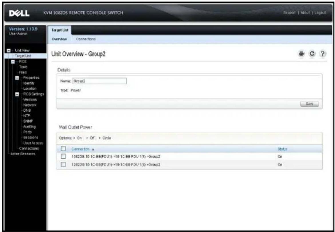
Default Outlet Names
On the Power Devices page, the checkbox “Assign Default Names to Outlets’ controls whether or not power outlets are given default names for a power device, as shown in the following figure. Only power outlets with names are listed on the Target page. Default assigned power outlet names may be removed by clearing the "Assign Default Names to Outlets" checkbox and saving. Power outlets without names are assigned default names by turning on “Assign Default Names to Outlets” and saving.
Figure 3.5: RCS Power Devices Page
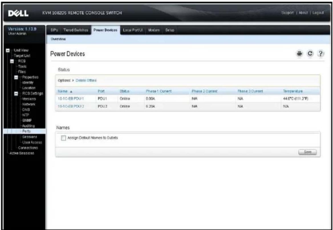
Assigning an Outlet Name
On the Power Device Outlet Settings page, three options are available for assigning the name of a outlet as shown in the following figure. The opt Manual Name assignment, Link to Target Device and Do Not Display as Device.
Figure 3.6: Power Device Outlet Settings Page
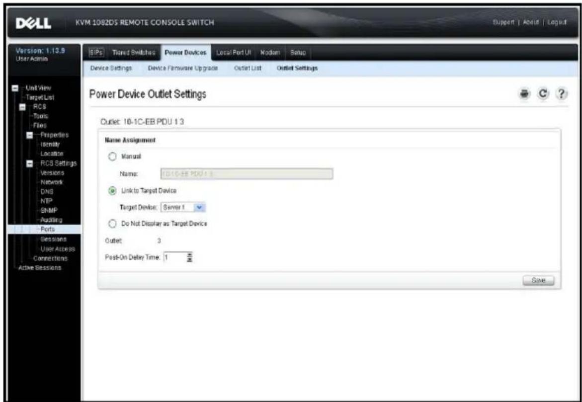
- The Manual Name assignment gives a unique name to an outlet. The name must be unique for all the SIPs and power outlet names. An attempt to specify a manual name which is not unique will result in an error and name will not be saved.
- The Link to Target List assignment links the outlet to another target nan (either an outlet or SIP) for power control of the named target. When outlet is linked to a SIP target name, typically the outlet physically prov power to the server attached to the SIP.
- The Do Not Display as Target Device option gives the outlet a blank name which prevents it from being displayed on the Target List page. This op may be used for spare outlets to remove them from the Target List page
Access Control Inheritance
When a power outlet name is changed by linking it to a target, the outlet inherits the access control already configured for that target name. When a is added, if the name retrieved from the SIP matches the name of an exis
target, the new SIP inherits the access control from that target. When a device is renamed, all the SIPs and outlets of that target are renamed, an carry forward the access control previously configured for the old target nar
Renaming of a Target Device
On the Target List - Overview page, the name for that target may be of any unique target name. The name must be unique for the set of all ta including SIPs and power outlets. When a target is renamed, all outlets li that target are also given the new target name.
Prioritized Status of Target Devices
On the Target List page, a target with linked power outlets controls multi devices. The Status value displayed for a target is chosen as the highest of all the status values of the devices. The following table shows the post-status values in priority order (highest to lowest) and the applicable target device types.
Table 3.4: Target Status Values
| Status Value Applicable for: Status Description | |
| SIP | Power Outlet |
| In Use x N/A A session is active | |
| Path Blocked x N/A | Path to Target is in use by another session |
| Upgrading x N/A SIP is being upgraded | |
| Turning On N/A x | One or more outlets are turning on |
| Turning Off N/A x | One or more outlets are turning off |
| Status Value Applicable for: Status Description | ||
| SIP | PowerOutlet | |
| No Power x N/A No power detected on SIP | ||
| Partial Power N/A x | Target has outlets in both on and off states | |
| Locked-Off N/A x | One or more outlets are locked on | |
| Turned Off N/A x | One or more outlets are turned off | |
| Locked-On N/A x | One or more outlets are locked off | |
| Idle | x N/A | No session active; SIP has power |
| Turned On | N/A x Outlets are turned on | |
When a target device has multiple power outlets linked by name and they do not have a common power state, the RCS may consider the Locked-Off outlet status as Off, and the Locked-On outlet status as On. The following table lists the resulting Status values for combinations of two outlet status values.
Table 3.5: Multiple Outlet Status Values and Displayed Status
| Outlet 1 Status | Outlet 2 Status | Resulting Status |
| Off | Off | Off |
| Off | On | Partial Power |
| On | On | Powered On |
| Locked-On | On Powered On | |
| Locked-On | Locked-On Locked-On | |
| Locked-On | Off Partial Power | |
| Locked-Off | On Partial Power | |
| Locked-Off | Locked-Off Locked-Off | |
| Locked-Off | Off Powered Off | |
| Locked-On | Locked-Off Partial Power |
Local Session Page on the Local Port
On the local port's Local Session page, when the target of the active session power outlets linked, three power controls are displayed on the page under Active session. The following figure illustrates the power controls displayed for an active local port session for a target named Server2.
Figure 3.7: Local Session Page With Power Controls
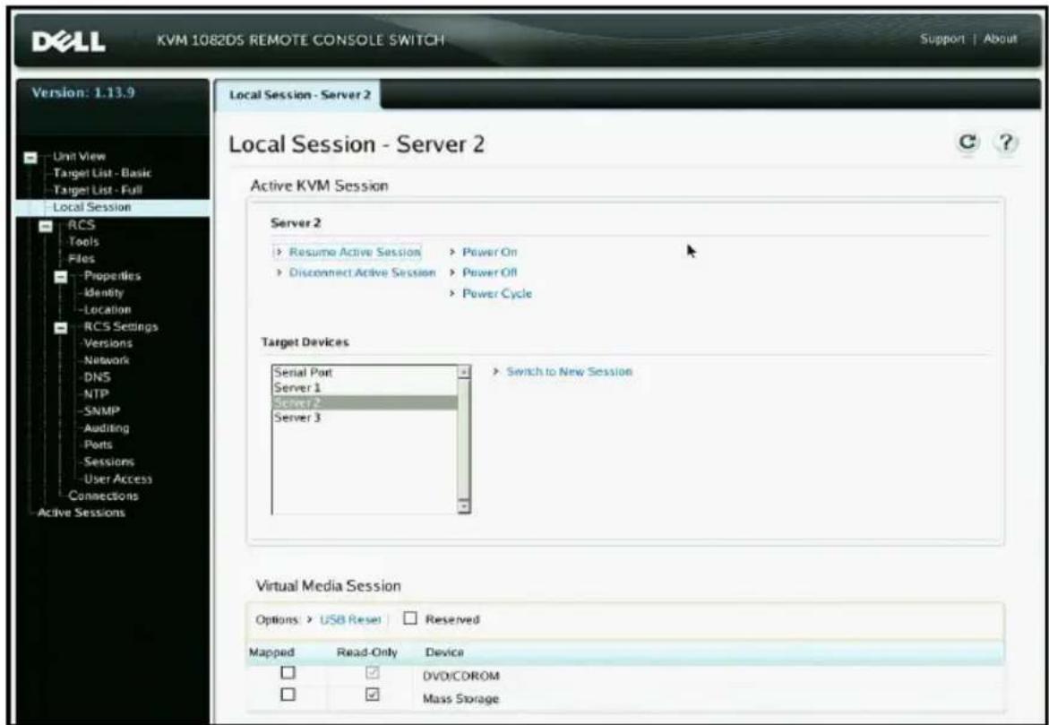
Local Port UI Settings
To change how the local UI is invoked:
1 From the side navigation bar, select Ports - Local Port UI to open the Local Port UI Settings screen.
2 Under the Invoke Local Port UI heading, select the checkbox next to one more of the listed methods.
3 Click Save.
You can turn on or turn off local port user interface authentication and choose user access level. If you turn on local port user interface authentication, you should be required to log in to use the interface.
You can also select the keyboard language for the local port, scan mode tin enable/disable the local port password and select a user preemption level. The
preemption level of users determines whether they may disconnect another or serial or KVM session with a target device. Preemption levels range from 1 to 4 with 4 being the highest level. For example, a user with a preemption level may preempt other level 4 users, as well as those with a level 1, 2, or To change the Local Port User Authentication (Administrator only):
1 From the side navigation bar, select Ports - Local Port UI to open the Local Port UI Settings screen.
2 Select or deselect the Disable Local Port User Authentication checkbox.
3 If Disable Local Port User Authentication is checked, select one of the following options from the User Access Level drop-down menu: User, User Administrator, or RCS Administrator.
4 Click Save.
Modem Settings
From the RCS Modem Settings screen, you can configure several modem settings, as well as view the following modem settings: Local Address, Remote Address, Subnet Mask, and Gateway.
For information on connecting your switch to a modem, see "Connecting t RCS Hardware" on page 25.
To configure modem settings:
1 From the side navigation bar, select Ports - Modem to open the Modem Settings screen.
2 Either enable or disable the Modem sessions can preempt digital sessions checkbox.
3 Select an Authentication Timeout time from 30 to 300 seconds, and an Inactivity Timeout time from 1 to 60 minutes.
4 Select Save.
Setup Settings - Port Security
From the serial setup port, you can change the appliance network configuration enable debug information, and reset the appliance.
To enable a password to restrict access the serial setup port:
1 From the side navigation bar, select RCS Settings - Ports - Setup to display the Setup Port Settings page.
2 Click to enable the Enable Setup Port Security box.
3 Enter and confirm your password.
4 Click Save.
Sessions
From the Active Sessions screen, you can view a list of active sessions and following information about each session: Target Device, Owner, Remote Host, Duration, and Type.
Configuring General Sessions
To configure general session settings:
1 From the side navigation bar, select Sessions - General. The General Session Settings screen appears.
2 Select or deselect the Enable Inactivity Timeout checkbox.
3 In the Inactivity Timeout field, enter the amount of inactive time you want to pass before the session closes (from 1 to 90 minutes).
4 In the Login Timeout field, enter the amount of inactive time you want pass before you must log in again (from 21 to 120 seconds).
5 Select or deselect the Enable Preemption Timeout checkbox.
6 In the Preemption Timeout field, enter the amount of time (from 1 to seconds) that a prompt will be displayed to inform you that your session going to be preempted.
7 Select the applicable session sharing options (Enabled, Automatic, Exclusive, or Stealth).
8 Select the Input Control Timeout from 1 to 50, with 1 representing o tenth of a second.
9 Click Save.
Configuring KVM Sessions
To configure KVM session settings:
1 From the side navigation bar, select Sessions - KVM. The KVM Session Settings screen appears.
2 Select an encryption level for keyboard and mouse signals (128-bit SSL (ARCFOUR), DES, 3DES, or AES) and for video signals (128-bit SSL (ARCFOUR), DES, 3DES, AES, or None).
3 Select a language from the Keyboard drop-down menu.
4 If your hardware includes the USB2+CAC SIP, select the video resolution
5 Click Save.
Configuring Local Virtual Media Sessions
To set virtual media options:
1 From the side navigation bar, select Sessions - Virtual Media to open the Virtual Media Session Settings screen.
2 Either enable or disable the Virtual Media locked to KVM Sessions checkbox.
3 Either enable or disable the Allow Reserved Sessions checkbox.
4 Select one of the following options from the Virtual Media Access Mod from the drop-down menu: Read-Only or Read-Write.
5 Select one of the Encryption Levels that you wish to be supported.
6 Click Save.
7 Select the checkbox next to each SIP for which you want to enable virt media and click Enable VM.
-Or-
Select the checkbox next to each SIP for which you want to disable virtual media and click Disable VM.
Virtual Media Options
You can determine the behavior of the switch during a virtual media session using the options provided in the Virtual Media Session Settings screen. Tabl 3.4 outlines the options that can be set for virtual media sessions.
For information about using virtual media in a KVM session, see "Virtual Me on page 96.
Table 3.6: Virtual Media Session Settings
| Setting Description | |
| Session Settings:Virtual Media locked to KVM Session | The locking option specifies whether a virtual media session is locked to the KVM session of the target device. When locking is enabled (default) and the KVM session is closed, the virtual media session will also be closed. When locking is disabled and the KVM session is closed, the virtual media session will remain active. |
Setting Description
| Session Settings: Allow Reserved Sessions | Ensures that a virtual media connection can only be accessed with your username and that no other user can create a KVM connection to that target device. When the associated KVM session is disconnected, the virtual media session may be disconnected according to the Locked setting in the Virtual Media dialog box. |
| Drive Mappings: Virtual Media Access Mode | You may set the access mode for mapped drives to read-only or read-write. When the access mode is read-only, the user will not be able to write data to the mapped drive on the client server. When the access mode is read-write, the user will be able to read and write data from/to the mapped drive. If the mapped drive is read-only by design (for example, a CD-ROM drive, DVD-ROM drive or ISO images), the configured read-write access mode will be ignored. Setting the read-only mode can be helpful when a read-write drive such as a mass storage device or a USB removable media is mapped, and you wish to prevent the user from writing data to it.You can have one DVD drive and one mass storage device mapped concurrently. A CD drive, DVD drive, or ISO disk image file is mapped as a virtual CD/DVD drive. |
| Encryption Level | You may configure encryption levels for virtual media sessions. The choices are: None (default), 128-bit SSL (ARCFOUR), DES, 3DES, and AES. |
| Setting Description | |
| Virtual Media Access per SIP:Enable VM/Disable VM | The Virtual Media Access per the SIP section lists all virtual media SIPs. The list includes details about each cable, including the option to enable or disable virtual media for each cable. |
Local Users
Local users can also determine the behavior of virtual media from the Local Session screen. In addition to connecting and disconnecting a virtual media session, you can configure the settings in the following table.
Table 3.7: Local Virtual Media Session Settings
| Setting Description | |
| CD ROM/DVD ROM | Allows virtual media sessions to the first detected CD-ROM or DVD-ROM (read-only) drives. Enable this checkbox to establish a virtual media CD-ROM or DVD-ROM connection to a target device. Disable to end a virtual media CD-ROM or DVD-ROM connection to a target device. |
| Mass Storage | Allows virtual media sessions to the first detected mass storage drive. Enable this checkbox to establish a virtual media mass storage connection to a target device. Disable to end a virtual media mass storage connection to a target device. |
| Reserved | Ensures that a virtual media connection can only be accessed with your username and that no other user can create a KVM connection to that target device. |
Configuring Serial Sessions
To configure serial session settings:
1 From the side navigation bar, click Sessions - Serial to display the Serial Session Settings screen.
2 Either enable or disable the Telnet Access Enabled checkbox.
3 Click Save.
Setting Up User Accounts
Managing Local Accounts
The switch OBWI provides local and login security through administrator-defined user accounts. By selecting User Accounts on the side navigation bar, administrators may add and delete users, define user preemption, and access levels and change passwords.
Access Levels
When a user account is added, the user may be assigned to any of the access levels: RCS Administrators, User Administrators, and Users.
Table 3.8: Allowed Operations by Access Level
| Operation RCS Administrator User Administrator Users | |||
| Configure interface system-level settings | Yes No No | ||
| Configure access rights | Yes Yes | No | |
| Add, change and delete user accounts | Yes, for all access levels | Yes, for Users and User Administrators only | No |
| Change your own password | Yes Yes Yes | ||
| Access target device | Yes, all target devices | Yes, all target devices | Yes, if allowed |
To add a new user account (User Administrator or RCS Administrator only):
1 On the side navigation bar, select User Accounts - Local User Accounts to open the Local User Accounts screen.
2 Click the Add button.
3 Enter the name and password of the new user in the blanks provided.
4 Select the access level for the new user.
5 Select any of the available target devices that you wish to assign to the account and click Add.

NOTE: User Administrators and RCS Administrators can access all target devices.
6 Click Save.
To delete a user account (User Administrator or RCS Administrator only):
1 On the side navigation bar, select User Accounts - Local Accounts to open the Local User Accounts screen.
2 Click the checkbox to the left of each account that you wish to delete, click Delete.
To edit a user account (Administrator or active user only):
1 On the side navigation bar, select User Accounts - Local Accounts. The Local User Accounts screen is displayed.
2 Click the name of the user you wish to edit. The user profile will appe
3 Fill out the user information on the screen, then click Save.
Avocent Management Software Device IP Addresses
You can contact and register an unmanaged switch with an Avocent management software server by specifying the IP address of the managemen software server.
To configure the server IP address:
1 On the side navigation bar, select User Accounts - Avocent. The Avocent Management Software Settings screen is displayed.
2 Enter the server IP addresses that you want to contact. Up to four ac are allowed.
3 Use the scroll bar to select the desired retry interval.
4 To disassociate an RCS that has been registered with the server, click Disassociate button.
5 Click Save.
LDAP
The Dell 1082DS/2162DS/4322D RCS can authenticate and authorize users in a local database or by an external scalable distributed directory service using Dell RCS software or OBWI with LDAP (Lightweight Directory Assistance Protocol) support. Refer to the LDAP section for additional information on configuring and using LDAP on the RCS.
Override Admin
Should a network failure occur, an account is provided that may be used regardless of the unit's ability to authenticate against an LDAP server. Refe Configure the Override Admin Account in Chapter 5.
Active Sessions
From the Active Sessions screen, you can view a list of active sessions and following information about each session: Target Device, Owner, Remote Host, Duration, and Type.
Closing a Session
To close a session:
1 From the side navigation bar, select Active Sessions to display the RCS Active Sessions screen.
2 Click the checkbox next to the desired target device(s).
3 Click Disconnect.

NOTE: If there is an associated locked virtual media session, it will be disconnected.
To close a session (local users only):
1 From the side navigation bar, select Local Session.
2 Select the Disconnect Active Session checkbox.
The Video Viewer Window
The Video Viewer is used to conduct a KVM session with the target device attached to an switch using the OBWI. When you connect to a device u Video Viewer, the target device desktop appears in a separate window containing both the local and the target device cursors.
The switch OBWI software uses a Java-based program to display the Video Viewer window. The switch OBWI automatically downloads and installs the Video Viewer the first time it is opened.

NOTE: Java 1.6.0_11 or later is required to launch a session.
NOTE: The switch OBWI does not install the Java Resource Engine (JRE). The JRE is available as a free download from http://www.sun.com.

NOTE: The switch OBWI uses system memory to store and display images within Video Viewer windows. Each opened Video Viewer window requires additional system memory. An 8-bit color setting on the client server requires 1.4 MB of memory per Video Viewer window, a 16-bit color setting requires 2.4 MB and a 32-bit color setting requires 6.8 MB. If you attempt to open more Video Viewer windows than your system memory allows (usually four), you will receive an out-of-memory error and the requested Video Viewer window will not open.
If the device you are attempting to access is currently being viewed by an user, you will be prompted to preempt the other user if your preemption equal to or greater than the other user's preemption level. An RCS Admin can also disconnect an active user via the Active Session page. For more information, see "Active Sessions" on page 80.
Figure 4.1: Video Viewer Window (normal window mode)
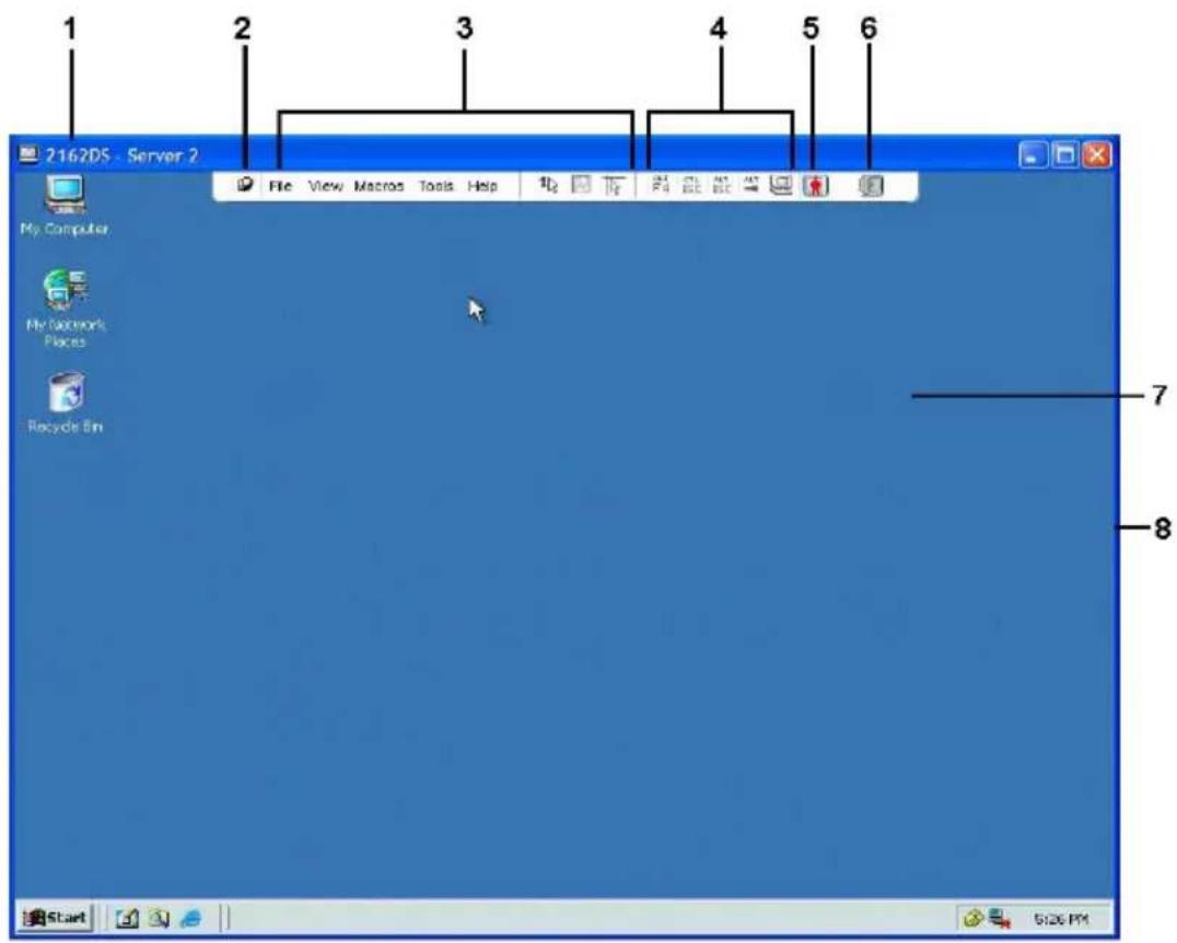
Table 4.1: Video Viewer Descriptions
| Number | Description |
| 1 | Title Bar: Displays the name of the target device being viewed. When in Full Screen mode, the title bar disappears and the target device name appears between the menu and toolbar. |
| 2 | Thumbtack icon: Locks the display of the menu and toolbar so that it is visible at all times. |
| 3 | Menu and toolbar: Enables you to access many of the features in the Video Viewer window. The menu and toolbar is in a show/hide state if the thumbtack has not been used. Place your cursor over the toolbar to display the menu and toolbar. Up to ten commands and/or macro group buttons can be displayed on the toolbar. By default, the Single Cursor Mode, Refresh, Automatic Video Adjust and Align Local Cursor buttons appear on the toolbar. For more information, see "Changing the Toolbar" on page 83 and "Macros" on page 104. |
| 4 | Macro buttons: Commonly used keyboard sequences that can be sent to the target device. |
| 5 | Connection Status Indicator: Indicates the status of the user that is connected to the RCS for this server. The modes are exclusive, basic active connection, primary active sharing, secondary active sharing, passive sharing, stealth, and scanning. |
| 6 | Smart Card Status Indicators: Indicate whether or not a smart card is in the smart card reader. The Video Viewer screen smart card icon is greyed out and indicates that the smart card option is unavailable or disabled. The icon is green if the smart card is mapped. |
| 7 | Display area: Accesses the server desktop. |
| 8 | Frame: Resizes the Video Viewer window by clicking and holding on the frame. |
Changing the Toolbar
You can choose the amount of elapsed time before the toolbar hides in the Video Viewer window when it is in show/hide state (that is, not locked in by the thumbtack).
To specify a toolbar hide time:
1 Select Tools - Session Options from the Video Viewer window menu.
-Or-
Click the Session Options button.
The Session Options dialog box appears.
2 Click the Toolbar tab.
3 Use the arrow keys to specify the number of elapsed seconds prior to hi the toolbar.
4 Click OK to save your changes and close the dialog box.
Launching a Session

NOTE: When using a non-proxied connection, video performance over a slower network connection may be less than optimal. Since certain color settings (such as Grayscale) use less network bandwidth than others (such as Best Color), changing the color settings can increase video performance. For optimal video performance over a slower network connection, use a color setting such as Grayscale/Best Compression or Low Color/High Compression. See "Adjusting the View" on page 85 for more information.

NOTE: If a user connects to a target device with a higher screen resolution than the local computer, the Video Viewer window will display a portion of the target device screen, with scroll bars for viewing the remainder of the screen. The user may view the entire screen by adjusting the resolution on the target device, the local computer or both.
To launch a KVM session from the switch Explorer window:
1 Click on a device listed on the Target List screen to open the unit over window.
2 Click the KVM Session link to open the Video Viewer in a new window.
Session Time-out
A remote session can time-out when no activity occurs in a Session window a specified time. The session time-out value can be configured in the RCS Session Settings window. The specified time-out value will be used the next time the switch OBWI is accessed.
To enable, disable, or configure the session time-out:
1 In the side menu, select Unit View - RCS - RCS Settings - Session General.
2 Select the desired setting for the Enable Activity Timeout box.
3 If necessary, select the time limit for the inactivity time-out.
4 Click Save.
Window Size

NOTE: The View - Scaling command is not available if the Video Viewer window is in Full Screen mode or to non-primary users of a shared session.
When the switch OBWI is used for the first time, any open Video View windows display at a resolution of 1024 x 768 until the user changes the Each Video Viewer window can be set to a different resolution.
The switch OBWI automatically adjusts the display if the window size cha during a session as long as autoscaling is enabled. If the target device res changes any time during a session, the display adjusts automatically.
To change the Video Viewer window resolution:
1 Select the View - Scaling command.
2 Select the desired resolution.
Adjusting the View
Using menus or task buttons in the Video Viewer window, you can do the following:
- Align the mouse cursors.
- Refresh the screen.
- Enable or disable Full Screen mode. When Full Screen mode is enabled, image adjusts to fit the desktop up to a size of 1600 x 1200 or 1680 (widescreen). If the desktop has a higher resolution, the following occurs:
- The full-screen image is centered in the desktop, and the areas surrounding the Video Viewer window are black.
• The menu and toolbar are locked so that they are visible at all time
- Enable automatic, full or manual scaling of the session image:
- With full scaling, the desktop window remains fixed and the device image scales to fit the window.
- With automatic scaling, the desktop window is sized to match the resolution of the target device being viewed.
- With manual scaling, a drop-down menu of supported image scaling resolutions is displayed.
- Change the color depth of the session image.
To align the mouse cursors:
Click the Align Local Cursor button in the Video Viewer window toolbar. The local cursor should align with the cursor on the remote device.

NOTE: If cursors drift out of alignment, turn off mouse acceleration in the attached device.
To refresh the screen, click the Refresh Image button in the Video Viewer window, or select View - Refresh from the Video Viewer window menu. The digitized video image is completely regenerated.
To enable Full Screen mode, click the Maximize button, or select View - Full Screen from the Video Viewer window menu. The desktop window disappears and only the accessed device desktop is visible. The screen resizes up to a maximum of 1600 x 1200 or 1680 x 1050 (widescreen). If the desktop has higher resolution, then a black background surrounds the full screen image. T floating toolbar appears.
To disable Full Screen mode, click the Full Screen Mode button on the floating toolbar to return to the desktop window.
To enable full scaling, select View - Scaling from the Video Viewer window menu and select Full Scale. The device image scales automatically to the resolution of the target device being viewed.
To enable manual scaling, select View - Scaling from the Video Viewer window menu. Choose the dimension to scale the window. The available manual so sizes will vary according to your system.
Refreshing the Image
Clicking the Refresh Image button in the Manual Video Adjust dialog box completely regenerates the digitized video image.

NOTE: You can also select View - Refresh from the Video Viewer window menu to refresh the image.
Video Settings
Additional Video Adjustment
Generally, the Video Viewer window automatic adjustment features optimize the video for the best possible view. However, users can fine-tune the video the help of Dell Technical Support by selecting the Tools - Manual Vid Adjust command in the Video Viewer window menu or clicking the Manual Video Adjust button. This displays the Manual Video Adjust dialog box. V adjustment is a per target setting.
Users can also verify the level of packets per second required to support screen by observing the packet rate located in the lower left-hand corner of dialog box.
To manually adjust the video quality of the window:

NOTE: The following video adjustments should be made only with the help of Dell Technical Support.
1 Select Tools - Manual Video Adjust from the Video Viewer window menu.
-Or-
Click the Manual Video Adjustbutton.
The Manual Video Adjust dialog box appears.
Figure 4.2: Manual Video Adjust Dialog Box
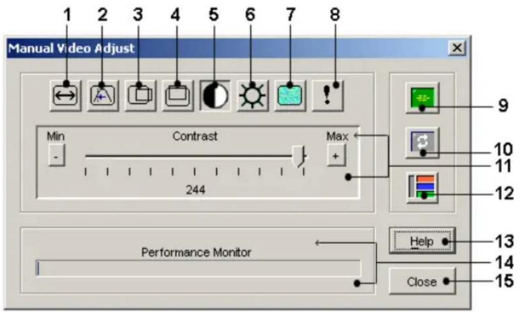
Table 4.2: Descriptions for Figure 4.2
| Number Description Number Description | ||
| 1 Image Capture Width 9 | Automatic Video Adjustment | |
| 2 Pixel Sampling/Fine Adjust 10 Refresh Image | ||
| 3 | Image Capture Horizontal Position | 11 Adjustment bar |
| Number | Description | Number | Description |
| 4 | Image Capture Vertical Position | 12 Video Test Pattern | |
| 5 | Contrast 13 Help | ||
| 6 | Brightness 14 Performance Monitor | ||
| 7 | Noise Threshold 15 Close button | ||
| 8 | Priority Threshold | ||
2 Click the icon corresponding to the feature you wish to adjust.
3 Move the Contrast slider bar and then fine-tune the setting by clicking the Min (-) or Max (+) buttons to adjust the parameter for each icon pressed. The adjustments display immediately in the Video Viewer window.
4 When finished, click Close to exit the Manual Video Adjust dialog box.
Target Video Settings
The Image Capture Width, Pixel Sampling/Fine Adjust, Image Capture Horizontal Position and Image Capture Vertical Position adjustments affect how the target video is captured and digitized. They are seldom changed.
The image capture parameters are automatically changed by the Automatic Adjustment function. A special image is required on the target in order to accurate adjustments independently.
Automatic Video Adjustment
In most cases, you do not need to alter the Video Settings from the default settings. The system automatically adjusts and uses the optimal video parameters. The switch OBWI performs best when the video parameters are such that no (0) video packets are transmitted for a static screen.
You can easily adjust your video parameters to ideal settings by clicking on Auto Adjust Video button in the Manual Video Adjust dialog box.

NOTE: You can also select Tools - Automatic Video Adjust from the Video Viewer window menu or click the Automatic Video Adjust toolbar icon to automatically adjust the video.
Video Test Pattern
Clicking the Video Test Pattern button in the Manual Video Adjust dialog box toggles a display of a video test pattern. Click the Video Test Pattern button again to toggle back to a normal video image.
Vendor-specific Video Settings
Video settings vary significantly among manufacturers. Dell maintains an online database of optimized video settings for various video cards, particularly Sun-specific ones. This information can be obtained from the Dell online knowledge base or by calling Dell technical support.
Color Settings
Adjusting Color Depth
The Dambrackas Video Compression® (DVC) algorithm enables users to adjust the number of viewable colors in a remote session window. You can choose display more colors for the best fidelity or fewer colors to reduce the volume data transferred on the network.
Video Viewer windows can be viewed using the Best Color Available (slower updates), Best Compression (fastest updates), a combination of Best Color and Best Compression or in Grayscale.
You can specify the color depths of individual ports and channels by selectir the View Color command in a remote session window. These settings are saved individually per channel.
Contrast and Brightness
If the image in the Video Viewer window is too dark or too light, select Automatic Video Adjust or click the Automatic Video Adjust button. This command is also available in the Video Adjustments dialog box. In most of this corrects video issues.
When clicking Auto Adjust several times does not set the contrast and brightness as desired, adjusting the contrast and brightness manually can he Increase the brightness. Do not go more than 10 increments before moving contrast. Generally, the contrast should be moved very little.
Noise Settings
Detection Thresholds
In some cases, noise in the video transmission keeps the packets/sec count which is indicated by small dots changing in the area of the cursor when moved. Varying the threshold values may result in “quieter” screens and ca improve cursor tracking.
You can modify Noise Threshold and Priority Threshold values if you are standard video compression. You can restore default threshold values by click Auto Adjust Video.

NOTE: Leaving the noise threshold at zero triggers constant video refresh, resulting in high network usage and a flickering video. It is recommended that the noise threshold be set at the highest level that allows efficient system performance, while still being able to recover pixel colors that the mouse cursor travels over.

NOTE: When adjusting the noise threshold, the slider bar is used for large adjustments and the Plus (+) and Minus (-) buttons at either end of the slider bar are used for fine-tuning.
See "Adjusting the View" on page 85 for information about changing the depth.
Mouse Settings
Adjusting Mouse Options
The Video Viewer window mouse options affect cursor type, Cursor mode, scaling, alignment and resetting. Mouse settings are device-specific; that is, the may be set differently for each device.

NOTE: If the device does not support the ability to disconnect and reconnect the mouse (almost all newer PCs do), then the mouse will become disabled and the device will have to be rebooted.
Cursor Type
The Video Viewer window offers five appearance choices for the local mouse cursor. You can also choose no cursor or the default cursor.
In Single Cursor mode, the display of the local (second) cursor in the Vide Viewer window turns off and only the target device mouse pointer is visible. only mouse movements that appear are those of the target device remote cu Use Single Cursor mode when there is no need for a local cursor.
Figure 4.3: Video Viewer Window With Local and Remote Cursors Displayed
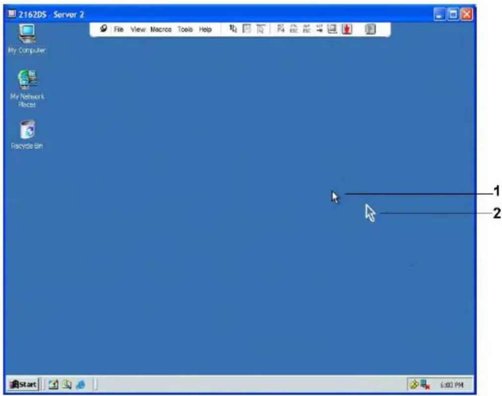
Table 4.3: Descriptions for Figure 4.3
| Number Description |
| 1 Remote Cursor |
| 2 Local Cursor |
The Cursor mode status of the Video Viewer window displays in the title including the keystroke that will exit Single Cursor mode. You can define keystroke that will exit Single Cursor mode in the Session Options dialog

NOTE: When using a device that captures keystrokes before they reach the client server, you should avoid using those keys to restore the mouse pointer.
To enter Single Cursor mode, select Tools - Single Cursor Mode from the Video Viewer window menu, or click the Single Cursor Mode button. The local cursor does not appear and all movements are relative to the target device.
To select a key for exiting Single Cursor mode:
1 Select Tools - Session Options from the Video Viewer window menu.
-Or-
Click the Session Options button.
The Session Options dialog box appears.
2 Click the Mouse tab.
3 Select a terminating keystroke from the drop-down menu in the Single Cursor mode area.
4 Click Save to save settings.
When you enable Single Cursor mode, you can press the specified key to return to Regular Desktop mode.
To exit Single Cursor mode, press the key on the keyboard that is identified the title bar.
To change the mouse cursor setting:
1 Select Tools - Session Options from the Video Viewer window menu.
-Or-
Click the Session Options button.
The Session Options dialog box appears.
2 Click the Mouse tab.
3 Select a mouse cursor type in the Local Cursor panel.
4 Click OK to save settings.
Mouse Scaling
Some earlier versions of Linux did not support adjustable mouse acceleration. For installations that must support these earlier versions, you can choose at three pre-configured mouse scaling options or set your own custom scaling. pre-configured settings are Default (1:1), High (2:1) or Low (1:2):
- In a 1:1 scaling ratio, every mouse movement on the desktop window: an equivalent mouse movement to the target device.
- In a 2:1 scaling ratio, the same mouse movement sends a 2X mouse movement.
• In a 1:2 scaling ratio, the value is 1/2X.
To set mouse scaling:
1 Select Tools - Session Options from the Video Viewer window menu.
-or- Click the Session Options button. The Session Options dialog box appears.
2 Click the Mouse tab.
3 To use one of the pre-configured settings, check the appropriate radio button.
-or- To set custom scaling:
a. Click the Custom radio button to enable the X and Y fields.
b. Type a scaling value in the X and Y fields. For every mouse input mouse movements are multiplied by the respective X and Y scaling factors. Valid input range is 0.25-3.00.
Mouse Alignment and Synchronization
Because the switch OBWI cannot get constant feedback from the mouse, t are times when the mouse on the switch may lose sync with the mouse
host system. If your mouse or keyboard no longer responds properly, you can align the mouse to reestablish proper tracking.
Alignment causes the local cursor to align with the remote target device's cu Resetting causes a simulation of a mouse and keyboard reconnect as if you disconnected and reconnected them.
To realign the mouse, click the Align Local Cursor button in the Video Viewer window toolbar.
Virtual Media
The virtual media feature allows the user on the client server to map a ph drive on that machine as a virtual drive on a target device. The client serv also add and map an ISO or floppy image file as a virtual drive on the t device. You may have one CD drive and one mass storage device mapped concurrently.
- A CD/DVD drive, disk image file (such as an ISO or floppy image file) mapped as a virtual CD/DVD-ROM drive.
- A floppy drive, USB memory device or other media type is mapped as a virtual mass storage device.
For information on configuring virtual media settings using the OBWI, see "Configuring Local Virtual Media Sessions" on page 73.
Requirements
The target device must support virtual media and be connected to the KVM switch with a USB2 or USB2+CAC SIP.
The target device must be intrinsically able to use the types of USB2-comp media that you virtually map. In other words, if the target device does not support a portable USB memory device, you cannot map that on the client server as a virtual media drive on the target device.
The user (or user group to which the user belongs) must have permission establish virtual media sessions and/or reserved virtual media sessions to the target device. See "Setting Up User Accounts" on page 77.
Only one virtual media session may be active to a target device at one
Sharing and Preemption Considerations
The KVM and virtual media sessions are separate; therefore, there are man options for sharing, reserving or preempting sessions. The Avocent management software has the flexibility to accommodate the system needs.
For example, the KVM and virtual media sessions may be locked together. this mode, when a KVM session is disconnected, so is the associated virtual media session. If the sessions are not locked together, the KVM session can closed but the virtual media session will remain active. This could be designed to perform a user is performing a time-intensive task using the virtual media session as an operating system load), and wants to establish a KVM session with different target device to perform other functions while the operating system load progresses.
Once a target device has an active virtual media session without an associative KVM session, two situations can occur - the original user (User A) reconnect or a different user (User B) can connect to that channel. You are an option in the Virtual Media dialog box (Reserved) that allows only the A to access that channel with a KVM session.
If User B is allowed to access that session (the Reserved option is not e User B could control the media that is being used in the virtual media By using the Reserved option in a tiered environment, only User A could the lower switch and the KVM channel between the upper switch and low switch would be reserved for User A.
Virtual Media Dialog Box
The Virtual Media dialog box allows you to manage the mapping and unmapping of virtual media. The dialog box displays all the physical drives
the client server that can be mapped as virtual drives. You may also add I floppy image files and then map them using the Virtual Media dialog box.
After a device is mapped, the Virtual Media dialog box Details View displays information about the amount of data transferred and the time elapsed since device was mapped.
You may specify that the virtual media session is reserved. When a session reserved, and the associated KVM session is closed, another user cannot launch KVM session to that target device. If a session is not reserved, another KVM session may be launched.
You may also reset the SIP from the Virtual Media dialog box. This action reset every form of USB media on the target device. It should be used with caution and only when the target device is not responding.
Opening a Virtual Media Session
To launch a virtual media session:
Select Tools - Virtual Media from the Video Viewer menu. The Virtual Media dialog box will appear. To make this a reserved session, click Details, then select the Reserved checkbox.
Figure 4.4: Video Viewer Virtual Media Dialog Box
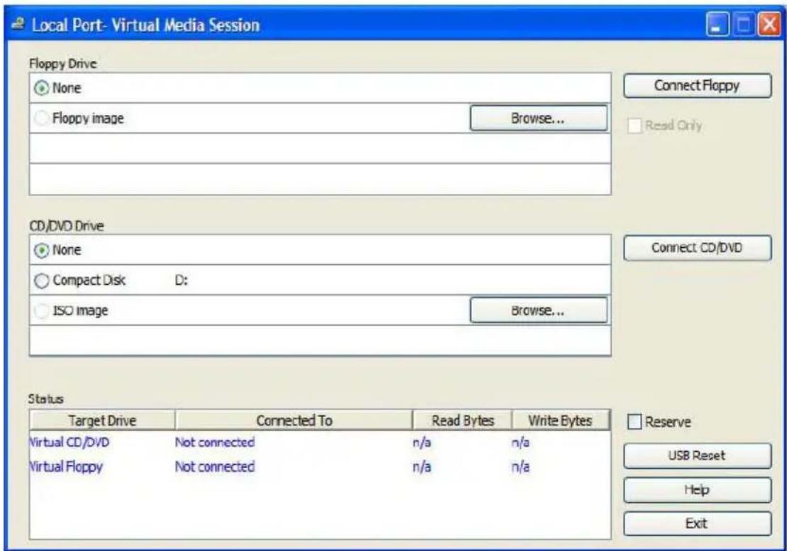
To map a virtual media drive:
1 Open a virtual media session from the Video Viewer menu by selecting Tools - Virtual Media.
2 To map a physical drive as a virtual media drive:
a. In the Virtual Media dialog box, click the Mapped checkbox next to the drive(s) you wish to map.
b. If you wish to limit the mapped drive to read-only access, click the Read Only checkbox next to the drive. If the virtual media session settings were previously configured so that all mapped drives must be read only, this checkbox will already be enabled and cannot be changed. You might wish to enable the Read Only checkbox if the session settings enabled read and write access, but you wished to limit a particular drive's access to read only.
3 To add and map an ISO or floppy image as a virtual media drive:
a. In the Virtual Media dialog box, click Add Image.
b. The common file dialog box will appear, with the directory containing disk image files (that is, those ending in .iso or .img) displayed. Select the desired ISO or floppy image file and click Open.
-or- If the client server's operating system supports drag-and-drop, select the desired ISO or floppy image file from the common file dialog box, and drag it onto the Virtual Media dialog box.
c. The file's header is checked to ensure it is correct. If it is, the com file dialog box will close and the chosen image file will appear in the Virtual Media dialog box, where it can be mapped by clicking the Mapped checkbox.
d. Repeat steps a through c for any additional ISO or floppy images you wish to add. You may add any number of image files (up to the l imposed by memory), but you may only have one virtual CD or DV or virtual mass storage mapped concurrently.
If you attempt to map too many drives (one CD or DVD and one mass device) or too many drives of a particular type (more than one CD or DVD mass storage device), a message will be displayed. If you still wish to map drive, you must first unmap an existing mapped drive, then map the new c After a physical drive or image is mapped, it may be used on the target c To unmap a virtual media drive:
1 In the Virtual Media dialog box, uncheck the Mapped checkbox next to the drive you wish to unmap.
2 You will be prompted to confirm. Confirm or cancel the unmapping.
3 Repeat for any additional virtual media drives you wish to unmap.
To display virtual media drive details:
In the Virtual Media dialog box, click Details. The dialog box expands to display the Details table. Each row indicates:
- Target Drive - Name used for the mapped drive, such as Virtual CD Virtual CD 2.
- Mapped to - Identical to Drive information that appears in the Client Drive column.
- Read Bytes and Write Bytes - Amount of data transferred since the mapping.
• Duration - Elapsed time since the drive was mapped.
To close the Details view, click Details again.
To reset all USB devices on the target device:

NOTE: The USB reset feature resets every USB device on the target device, including the mouse and keyboard. It should only be used when the target device is not responding.
1 In the Virtual Media dialog box, click Details.
2 The Details View will appear. Click USB Reset.
3 A warning message will appear, indicating the possible effects of the reset. Confirm or cancel the reset.
4 To close the Details view, click Details again.
Closing a Virtual Media Session
To close the Virtual Media dialog box:
1 Click Exit.
2 If you have any mapped drives, a message is displayed, indicating that drives will be unmapped. Confirm or cancel the operation.
If a user attempts to disconnect a virtual media session or an active KVM session that has an associated locked virtual media session, a confirmation message is displayed, indicating that any virtual media mappings will be log
Smart Cards
You can connect a smart card reader to an available USB port on the client server and access attached target devices on the switch system. You can then launch a KVM session to open the Video Viewer and map a smart card.

NOTE: For all smart card readers, you must use a Dell USB2+CAC SIP or an Avocent VMC IQ module.
The smart card status is indicated by the smart card icon at the far right Video Viewer toolbar. The following table describes the smart card status icon
Table 4.4: Smart Card Icons
| Icon Description | |
 | A smart card is not in the smart card reader, or a smart card reader is not attached. |
 | A smart card is in the smart card reader but has not been mapped yet. |
| [DBGH] | A smart card is mapped (green icon). |
To map a smart card:
1 Open a KVM session to display the Video Viewer window menu.
2 Insert a smart card into the smart card reader attached to your client sc
3 Click Tools - Map Smart Card on the Video Viewer window menu.
4 If no smart card is mapped to the target device, the No Card Mapped option will have a dot beside it. Select your smart card, listed below the option, to map the smart card.
To unmap a smart card, close out the KVM session by clicking X in the Viewer window menu, selecting Tools - No Card Mapped, and either removing
the smart card from the smart card reader or disconnecting the smart card from the client server.
Keyboard Pass-through
Keystrokes that a user enters when using a Video Viewer window may be interpreted in two ways, depending on the Screen mode of the Video View window.
- If a Video Viewer window is in Full Screen mode, all keystrokes and keyboard combinations except Ctrl-Alt-Del are sent to the remote target device being viewed.
- If a Video Viewer window is in Regular Desktop mode, Keyboard Pass-through mode can be used to control whether the remote target device local computer recognizes certain keystrokes or keystroke combinations.
Keyboard pass-through must be specified using the Session Options dialog by When enabled, keyboard pass-through sends all keystrokes and keystroke combinations except Ctrl-Alt-Del to the remote target device being viewed when the Video Viewer window is active. When the local desktop is active keystrokes and keystroke combinations entered by the user affect the local computer.

NOTE: The Ctrl-Alt-Del keyboard combination can be sent only to a remote target device by using a macro.

NOTE: The Japanese keyboard ALT-Han/Zen keystroke combination is always sent to a remote target device regardless of the Screen mode or keyboard pass-through setting.
To specify keyboard pass-through:
1 Select Tools - Session Options from the Video Viewer window menu.
-Or-
Click the Session Options button.
The Session Options dialog box appears.
2 Click the General tab.
3 Select Pass-through all keystrokes in regular window mode.
4 Click OK to save setting.
Macros
The switch OBWI comes pre-configured with macros for the Windows, Linux, and Sun platforms.
To send a macro, select Macros -
Saving the View
You can save the display of a Video Viewer either to a file or to the clip pasting into a word processor or other program.
To capture the Video Viewer window to a file:
1 Select File - Capture to File from the Video Viewer window menu.
-Or-
Click the Capture to File button.
The Save As dialog box appears.
2 Enter a filename and choose a location to save the file.
3 Click Save to save the display to a file.
To capture the Video Viewer window to your clipboard, select File - Captu Clipboard from the Video Viewer window menu, or click the Capture to Clipboard button. The image data is saved to the clipboard.
Closing a Session
To close a Video Viewer window session:
Select File - Exit from the Video Viewer window.
LDAP Feature for the RCS
LDAP is a protocol standard used for accessing and updating a directory to TCP/IP. The Dell RCS software and OBWI supports both standard and D-extended schema, and offers strong security features including authentication, privacy, and integrity.

NOTE: Windows 2008 Server is required to use LDAP in IPv6 mode.
NOTE: Use of Microsoft Active Directory to recognize RCS users is supported on the Microsoft Windows® 2000 and Windows Server 2003 operating systems.
The Structure of Active Directory
An Active Directory (AD) deployment consists of a distributed database containing hierarchical structures of objects. Each object is associated with a object class that determines what kinds of data can be stored in that object. The hierarchical structures begin with objects that represent AD domains, deployed to form a hierarchy of domain names that can be represented in diagram the same way DNS name spaces are usually depicted. Dell RCSs designed to support a single tree of domains that are deployed in either shallow or deep hierarchical name structure.
Domain Controller Computers
Associated with the Domain hierarchy is the corresponding hierarchy of Dor Controller computers where AD provides LDAP services. Each domain may have multiple peer Domain Controllers and may also be distributed across geographical sites. The suite of Dell RCSs is designed to support both of
aspects of AD. DNS is used to determine the network coordinates of each Domain Controller so that the Dell RCSs can gracefully handle situations which some Domain Controllers are not available on the network. DNS SRV records are used for this purpose so the Dell RCSs always attempt to contact alternative Domain Controllers at the nearest site first, depending on the administrative settings configured in the SRV records.
Object Classes
Within each domain, there is another hierarchy of objects designed to store information about various entities and groupings of entities. Such entities are represented in AD by object classes used to define “containers” that help organize groupings of objects. Other object classes represent entities such as network users, computers, printers, or network services. Two types of container object classes are of special interest: Group and Organizational Unit (OU). These two object classes allow the AD Administrator to define groupings of entities for the purpose of simplifying the application of access controls and other administrative policies. For example, a domain may be configured to have an OU container named Engineering, which contains several Group objects named according to function, like Hardware, Software, and Support; each of the groups is configured with a membership list of User objects and perhaps Computer objects. Yet another level of hierarchy can be configured by nesting groups; a nesting is formed by including the name of a Group object in the membership of another Group object. It should be noted here that each AD Group object has an associated scope that is used to configure the types of nesting relationships it is allowed to have with other groups; for example, which scope is set to Universal, the group may participate in nesting that crosses domain boundaries but when scope is set to Local it may not participate in such nesting. Rules for nesting are available in the AD product documentation available from Microsoft. The suite of Dell RCSs is designed to support all nesting rules defined for AD.
Attributes
There is one more hierarchy used in AD. Associated with each object class set of “attributes” used to store specific information about the entity that being represented. For example, associated with the User object class is an attribute type named SAM ACCOUNT NAME and others such as FIRST NAME, SURNAME, PASSWORD, etc. The suite of Dell Remote Console Switches uses the SAM ACCOUNT NAME and PASSWORD attributes to authenticate a user (the formal AD names for these two attributes are sAMAccountName and unicodePWD, respectively).
Schema Extensions
AD is packaged with many object classes, including default containers for Computer and User objects as well as classes for OU containers and classes represent computer and user entities. AD can be extended to include new classes such as those provided by Dell to simplify the administration of ac controls; such extensions are usually referred to as “schema extensions” and at the heart of the Dell Extended Schema feature described in this document. These schema extensions provide customized object classes to represent Dell RCSs, access control information, and a type of container used to associate specific access control information with specific instances of Dell RCSs and Users. It is important to note that each attribute type and object class u AD must have a globally unique identifier, known as an Object Identifier. These unique identifiers are ultimately managed by internationally recognized authorities. For AD, the OID space is managed secondarily by Microsoft. I has obtained OIDs for the custom object classes and attribute types used Dell Extended Schema feature. The following is a summary of the OIDs obtained:
Dell extension is: dell
Dell base OID is: 1.2.840.113556.1.8000.1280
RCS LinkID range is: 12070 to 12079
The suite of Dell RCSs is also designed to function using only object classes present in the AD packaged classes; this option is known as the Standard Schema. Under this option, the Computer object class is used to represent I RCSs and standard Group objects are used to associate specific access control information with specific instances of Dell RCSs and Users. In this case, access control information is stored in a specific attribute type in the Group object. The hierarchical structures present in AD can complicate your ability to access information stored in the directory objects. To avoid potential delays associated with navigation of the hierarchies, the suite of Dell Remote Console Switches designed to use an aspect of AD known as the Global Catalog (GC). The provides a “quick look-up” service by providing access to a subset of the data stored in the complete AD database and by “collapsing” all of the hierarchy and geographic distribution into a single relatively flat structure. The GC is queried using the same LDAP directory queries that work on the complete Database. The AD product requires at least one of the Domain Controllers in enterprise to also be configured to provide GC services and actual deployment of AD can have any or all of the Domain Controllers configured to provide services. The suite of Dell RCSs uses DNS to determine the network coordinates of each GC server so that the Dell RCSs can gracefully handle situations where some GC servers are not available on the network. DNS SR records are used for this purpose so that the Dell RCSs always attempt to contact alternative GC servers at the “nearest” site first, depending on the administrative settings configured in the SRV records.
Standard Schema versus Dell Extended Schema
To provide the greatest flexibility in the multitude of customer environments, Dell provides a group of objects that can be configured by the user depend the desired results. Dell has extended the schema to include an Association, Device, and Privilege object. The Association object is used to link together users or groups with a specific set of privileges to one or more SIPs. The Object defines the individual RCSs within the Active Directory structure and
the privilege object is linked to device objects via association objects to as usage permissions.
This model provides an Administrator maximum flexibility over the different combinations of users, privileges, and SIPs on the Remote Console Switch without adding too much complexity.
Before installing the Dell Schema Extensions, Administrators should read through the descriptions and instructions within this chapter to determine which schema is right for their particular installation. Altering a schema ob will cause it to propagate through Active Directory so that once it is created cannot be deleted. It can only be deactivated. Because of this, the benefit changing the schema should be carefully weighed before the effort is under
The primary benefit gained by installing the Dell Schema Extensions is to eliminate confusion. When using the standard Active Directory schema, a Remote Console Switch most closely matches a computer device object and configured as one. Since the RCS is not a computer, the schema function not all apply. Care will have to be taken to correctly configure an RCS designated in this manner.
In addition, using the Dell Schema Extensions makes it easier to search or identify switch devices. A switch that is configured using a computer device object will be searched on along with every computer device within the A Directory structure.
The RCS can authenticate equally well using either schema and no function is lost by using either method. Administrators are free to choose whichever method works within their particular installation. Instructions have been provided for installations with and without the Dell Schema extensions.
Sections and instructions that pertain to only one schema set will be marked such and may be ignored in installations where they are not used.
Standard Installation
Before a Dell RCS can use Active Directory for authentication:
1 Configure the Override Admin Account
2 Configure DNS Settings
3 Set the Network Time Protocol
4 Configure the Authentication Parameters
5 Configure Group Objects
6 Create and Download the CA Root certificate
7 Set the Login Timeout
Configure the Override Admin Account
Should a network failure occur, an account is provided that may be used regardless of the unit's ability to authenticate against an LDAP server. Before configuring other settings, this account should be configured. To configure the Override Admin Account in the on-board web interface:
1 Click User Accounts, then click Override Admin.
2 Type the username and password you wish to assign to the user and the verify the password by typing it in the Verify Password field.
3 Click Save.

NOTE: You must be logged in as admin for this option.
Configuring DNS Settings
Before the LDAP client can resolve names, at least one DNS server must be specified.
The Network sub-category displays the name of the RCS and allows you to change the network settings including the IP address, Subnet Mask, Gateway, LAN speed and DHCP/BootP setting. The name displayed for the RCS will the same as the name given in the System Name field in the SNMP categ
The Network sub-category allows the entry and maintenance of up to three Servers. These DNS servers are used to resolve DNS names provided on the LDAP authentication panel.

NOTE: At least one DNS server must be configured for the LDAP feature to work. Whenever a primary server is unavailable, the RCS software will automatically failover to backup DNS servers, as identified here.

NOTE: You can also set DNS server addresses using the RCS's serial administrative interface. For information about using the serial administrative interface, please consult your RCS documentation.
To configure the DNS settings in the on-board web interface:
1 Click DNS to open the DNS Settings screen.
2 Specify the DNS mode, enter the Server addresses, and click Save.
Figure 5.1: OBWI - DNS Settings
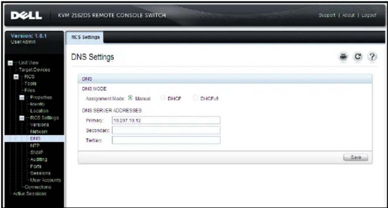
Configuring the Network Time Protocol (NTP) Settings
The switch must have access to the current time to verify that certificates not expired. You can configure the switch to request time updates from the NTP. To configure NTP settings in the on-board web interface:
1 Click NTP to open the NTP screen.
2 Click the Enable NTP box.
3 Enter the name of your network time source in the provided boxes. You may also set an hour interval to specify how often to request time updates. If the interval is set to 0, requests will only be made during RCS start when changes to the Global - NTP menu are made.
4 Click Save.
Configuring the LDAP Authentication Parameters
The Authentication panel allows RCS Administrators to configure the parameters required to access LDAP Directory Services. When access requests are received from users, the RCS can use LDAP protocols to send the user password, and other information to the Directory Service in determining what authorization permissions the user has.

NOTE: The terms for establishing LDAP configuration are, KVM User, KVM User Admin, and KVM Appliance Admin, They are equivalent to User, User Administrator and RCS Administrator, respectively. The access levels have not changed, but use the new terms as directed.
Enabling LDAP Authentication
The Operational Modes section on the LDAP Configuration Options screen allows you to choose the appropriate type of LDAP services to use for user
authentication. The available modes are:
• Standard LDAP directory services (non-Microsoft)
• Microsoft Active Directory services
- Disable LDAP authentication
If an alternate (non-LDAP) authentication method has already been selected use, then LDAP authentication will automatically be disabled. It will be necessary to deselect this method to use LDAP Directory Services.
To restore the ability to use LDAP authentication:
1 Under User Access, select the Avocent tab, see Figure 5.2.
2 Click Disassociate to deselect the use of the Avocent management authentication server.
3 Click Save.
Figure 5.2: The Avocent Authentication Screen
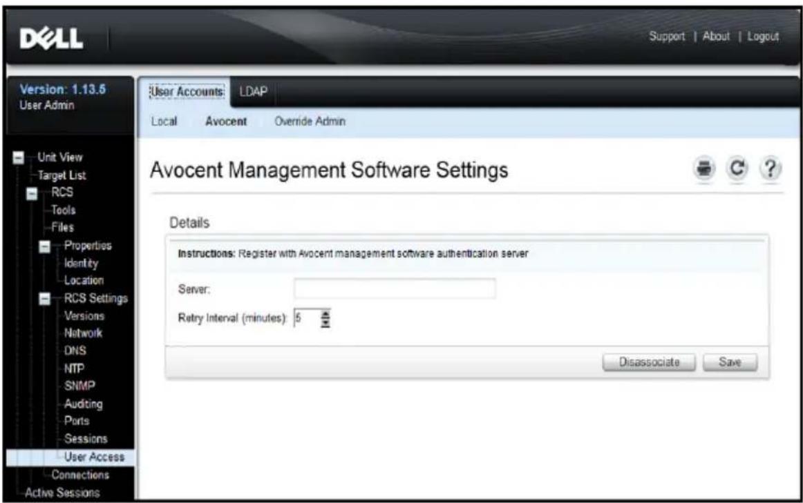

NOTE: It is possible to externally sever the Avocent authentication association without performing these steps. Nonetheless, if an Avocent server association has been created for user authentication, it must be expressly removed via this procedure to permit LDAP authentication configuration to proceed.
To enable LDAP Authentication:
1 Under User Access, select the LDAP tab, see Figure 5.3.
Figure 5.3: The LDAP Configuration Options Screen
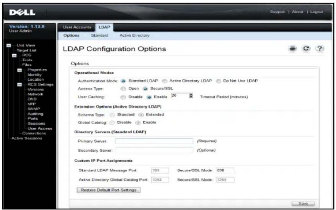
2 Select one of the available LDAP Authentication modes in the Operational Modes section.
3 Configuration options must be set to fully enable LDAP Authentication for use. Each of the options are detailed in this chapter.
4 Click Save.
To disable LDAP authentication, select the Do Not Use LDAP option, and click Save. All other options on the screen will be disabled; no editing of these
other fields will be permitted. In addition, the additional configuration screen under both the Standard and Active Directory tabs will also be disabled.
When LDAP Authentication is disabled, User Access will be adjudicated by either locally-defined user access lists or Avocent management software (see section on User Access).
When LDAP Authentication is enabled, locally-defined user access lists take precedence over requests to LDAP Directory Servers. User access requests will first check for RCS-defined users. If no match is found, then requests will sent to LDAP Directory Servers, as configured.
Entering Authentication Parameters - Operational Modes
Access type
LDAP Directory Servers may be setup to operate either in Open or Secure (using SSL - Secure Socket Layer encryption). The mode selected must make that of the host directory server. When selecting Secure/SSL mode, please see the section entitled LDAP SSL Certificates for guidance on meeting the requirements for encrypted operations.
User caching
Whenever a successful user authentication is completed via LDAP, the RCS the ability to retain the results obtained from the LDAP Directory Server selected period of time. If, during that time window, another access requests generated that normally would result in a repeat request of the Directory such requests are handled locally on board the RCS. This results in a ne instantaneous response that will allow the user to continue working with minimal delays.
The three settings for this configuration option are disable, enable, and tim period.
Disable - do not permit user caching, and always ask the LDAP Directory S for guidance on the authentication status for every user, every time it is required. By default, User Caching is disabled.
Enable - hold results of recent user authorization requests as determined by LDAP Directory Server. When identical authorization requests are received within a pre-determined time period, use those prior results to service the no request.
Timeout Period - establishes the duration of the time window. Values are recorded as minutes. Enter only the number in the box, or use the arrow controls.
- Default timeout value: 15 minutes
• Minimum timeout: 1 minute
• Maximum timeout: 1,000 minutes

NOTE: As with all configuration updates, you must click the Save to secure your changes. LDAP configuration changes are generally available to the RCS immediately, with no reboot required.
Entering Extension Options - Active Directory LDAP
When Active Directory mode is selected, administrators must determine if the Standard or Extended Schema will be employed. Additionally, administrators should declare whether the Microsoft Global Catalog option will be in use.
Entering Authentication Parameters - Standard LDAP
When using standard LDAP (not Microsoft Active Directory LDAP), direct entry of at least one relevant directory server address is required. Enter the addresses in the Primary Server and Secondary Server fields. The primary serv entry is required.
Server addresses may be entered in one of the following forms:
• DNS address (example: myldapserver.com)
- IPv4 address (example: 10.20.255.255)
- IPv6 address (example: fe80::200:f8af:fe20:76ce)
Entering Authentication Parameters - Custom IP Port Assignments
This section permits changes to the industry-standard IP Port numbers conventionally used for LDAP. In most instances, there should be no need change these values. However, if the administrator of the LDAP Directory you are using requires different port assignments, then those may be entered here.
Depending on the exact configuration, LDAP can make use up to four data IP Ports, and as many as two as a time. Slots for each of these four data the LDAP Configuration Options screen. Settings elsewhere on the same screen will be used to identify the ports that can be altered. The following chart conditions in which the available port slots are enabled and allowed to be
| List of Port Slots that are enabled and may be customized | Open Mode Secure/SSL Mode | |
| Not using Global Catalog | Standard LDAP Message Port | Standard LDAP Message Port - Secure/SSL Mode |
| Using Global Catalog | Standard LDAP Message Port and Active Directory Global Catalog Port | Standard LDAP Message Port - Secure/SSLMode and Active Directory Global Catalog Port - Secure/SSL Mode |
Table 5.1: Editing IP Port Assignments
If at any time, the original industry-standard IP Port designations need to restored, click on the 'Restore Default Port Settings' button. All four Port will be returned to their original values, which are:
Standard LDAP Message Port - 389
Standard LDAP Message Port via SSL - 636
Active Directory via Global Catalog server - 3268
Active Directory via Global Catalog server/SSL - 3269
IP Port numbers are permitted to range from 1 to 65535. Failure to match port numbers with those in use by the LDAP Directory Server will result in failure to establish communications with that server.
Completing LDAP Configuration
For both Standard and Active Directory LDAP modes, additional parameters are required to insure proper connectivity to the LDAP Directory Servers. These parameters are discussed in the following sections. However, you should be av that there are 'interlocks' established in the OBWI pages to assist the administrator by insuring that parameter updates are made on the appropriate page.
For example, if you were to select the Active Directory LDAP tab, you mig see the following display on your screen see Figure 5.4
Figure 5.4: Notification Message - LDAP Mode Not Enabled
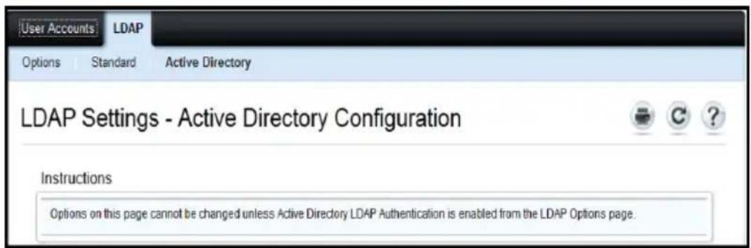
When this happens, it is an indication that the Active Directory mode has been enabled or it was enabled, but not saved. You should return to the I Options screen, select Active Directory LDAP, make note of the secondary parameters for this mode on that page, then click Save before returning to screen.
There is an equivalent display for Standard LDAP mode that appears when that mode is not enabled.
Secondary LDAP Settings - Standard Configuration
As with LDAP Active Directory Configurations, Standard LDAP authentication, search, and query parameters are configured through the remote OBWI. Settings in this section are accessed from the User Access / LDAP Standard tabs via the OBWI window shown here in Figure 5.5
Figure 5.5: Secondary LDAP Settings - Standard Configuration
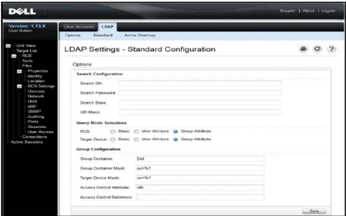

NOTE: While this section describes the setup parameters for connections being made to Standard LDAP Directory Servers, please also note that this section may also be used to establish connections to more generic versions of Active Directory services as well.
Setting up the RCS for performing Standard LDAP queries

NOTE: Before you can use any of the querying modes with Active Directory, you must update Active Directory so that the selected querying mode can assign the applicable authorization level for the user.
To set up group queries:
1 Log in to your LDAP Directory Server software with administrator privileges.
2 Create an organizational unit (OU) to be used as group container.
3 Create a computer object in with a name identical to the switching system for querying appliances or identical to the attached target devices for querying target devices. The name must match exactly and is case-sensitive
4 The appliance names and target device names used for group queries are stored in the appliance. The appliance name specified in the Appliance Overview screen of the remote OBWI and target device names must be comprised of any combination of upper-case and lower-case letters, digits, and hyphens, and must match the object names on the LDAP Server.
5 Create one or more groups under the group container organizational unit.
6 Add the usernames and the target device and appliance objects to the groups you created in step four (4).
7 Specify the value of an attribute used to implement the Access Control Attribute.
Search Configuration Settings
There are four settings that are required for successful LDAP connections. The are Search DN, Search Password, Search Base, and UID Mask.
Search DN
Search DN defines the administrator-level user that the target device uses to into the directory service. Once the target device is authenticated, the direct service grants it access to the directory to perform the user authentication queries specified on the LDAP query page. Each search value must be separated by a comma. A typical entry might look like this:
cn=Administrator, cn=Users, dc=MyDomainName, dc=com
Search password
Search password is used if a password is required for search options. It authenticates the administrator or user specified in the Search DN field. A printable ASCII characters are allowed.
Search base
Search Base defines a starting point from which all LDAP searches begin. default values are dc=yourDomainName and dc=com. Each search component must be separated by a comma. For example, to define a search base for test.com, your values are dc=test, dc=com.
UID mask
UID mask specifies the search criteria for User ID searches of LDAP target devices. The format is
Query Mode Selection Settings
Configure the Query Mode parameters for the appliance and target device. appliance is used to authenticate administrators and users attempting to access the console switch. The target device is used to authenticate users attempt to access attached target devices.
There are three query modes available. They are basic, user attribute, and attribute.
Basic
A username and password query for the user is sent to the directory serv Once authenticated as a valid user, the user is given access to the applia any attached target devices.
User attribute
A username, password, and Access Control Attribute query for the user is the directory service. The Access Control Attribute is read from the user of
in Active Directory. If no values are found, the user is given no access to appliance or target devices
Group attribute
A username, password, and group query sent to the directory service for an appliance and attached target devices when using Appliance query mode or for selected target device when using Target Device query mode. If a group is containing the user and appliance name, the user is given access to either the appliance or target devices when using Appliance query mode. If a group is found containing the user and target device IDs, the user is given access to selected target device when using Target Device query mode.

NOTE: Depending on the query mode selected, several of the configuration items on this screen may be enabled or disabled according to their applicability.
Group Configuration Parameters
There are several group configuration parameters available.
Group container
The group container specifies the OU created in Active Directory by the administrator as the location for group objects. Group objects can contain use computers, contacts, and other groups, each assigned with a certain access level
Group container mask
The group container mask defines the object type of the Group Container, normally an OU. The default value is ou=%1.
Target device mask
The target device mask defines a search filter for the target device. The def value is cn=%1.
Access control attribute
The access control attribute specifies the name of the attribute used when the query modes are set to User Attribute or Group Attribute. The default attrib
name is "info".
Access control delimiters
The LDAP Standards specify that the semi-colon character (;) is used to separate multiple properties within a single named attribute. Under normal circumstances, this need not be changed. For example, suppose we have a erase-board marker object in the LDAP Directory, and the attribute “Color” used to identify colors that this marker might have.
Color: red;blue;green:black;purple
"Color" is the name of the attribute; the rest represents the attribute's val this case a compound value. With compound values, the semi-colon is the delimiter used to mark the end of one component and the beginning of
In rare cases, an LDAP Administrator may need the semi-colon to be part value itself. In such instances, the Delimiter character has to be changed something else. If so, use this field to specify all of the characters (at le character is required; more than one is acceptable) that will identify how Access Control Attribute should be divided up. For example, the delimiter is set to # (three characters)
Color: red#blue\$green;black#purple
These delimiters would find the same five value components as in the first example above. LDAP Administrators should make sure that any Access Con Delimiter characters defined do not appear as values for any attributes else for any purpose other than that of delimiter.
As shown above, the Access Control Attribute (ACA) consists of a combination of a name and a value. By default, we search LDAP Directory entries that up the user and the target device, looking for attributes named ‘info’. When found, the value of such attributes should tell us the user’s authorization that device. If the LDAP Services Administrator wishes to use an attribute other than info, it may be customized via the field indicated above.
Because users may be members of several groups, and each group may have differing authorization levels to different devices, a running tally is kept of
results. By LDAP standards, the final authorization level reported is the higher (most permissive) level found among all positive results found for the specific user and device under scrutiny.
Secondary LDAP Settings - Active Directory Configuration
Settings in this section are accessed from the User Access / LDAP / Active Directory tabs via the OBWI window shown here in Figure 5.6.
Figure 5.6: Secondary LDAP Settings - Active Directory Configuration
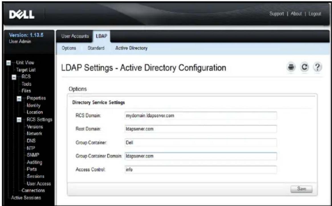
If you plan to install the Dell Extended Schema, enter only the RCS and Domains that will be used.
If you elect not to use the Dell Extended Schema, the RCSs and access controlled SIPs in your installation will be configured as Computer Objects within Active Directory. To do this, you will first need to configure an Organizational Unit to hold group objects that relate users to access controlle RCSs and their attached SIPs. This can be a previously created OU, or one created specifically for this purpose but it must be unique among all OU of in the Group Container domain.
Next, choose an attribute within the LDAP directory to be used to contain discretionary access control information. This should be a previously unused attribute that is capable of storing a string value. (The default is the “int attribute of the Group Object.)
Finally, you will need to enter the location for the Group Container, the Container Domain and the Access Control Attribute in the blanks provided the Global - Authentication window.
For more detailed descriptions of the Authentication panel fields, see Table To access the Authentication panel in the OBWI:
Click User Accounts, then click LDAP.
Figure 5.7: OBWI - Authentication Panel Local/LDAP and Parameters
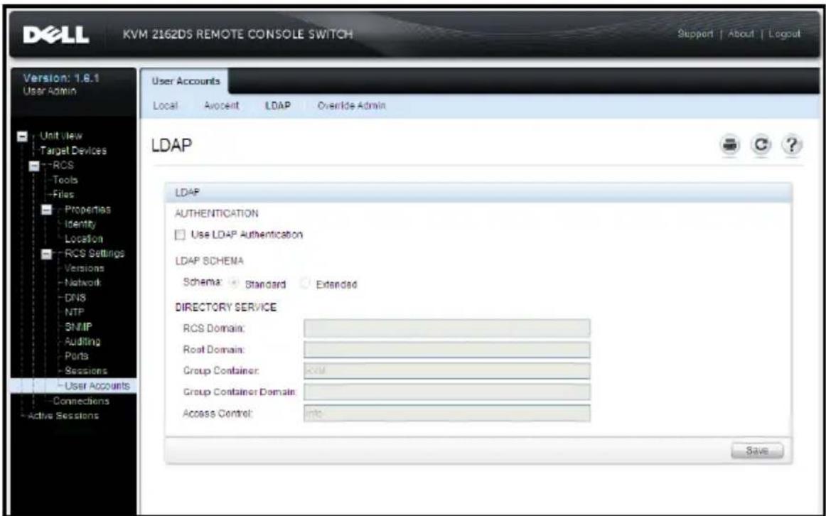
Table 5.2: Authentication Panel Field Descriptions
| Field Description | |
| Authentication Settings | Users can choose to use LDAP authentication by clicking the box shown.The user may still log in with the Override admin account if the LDAP servers are inaccessible. |
| Schema | Radio Button to indicate which Active Directory (AD) object classes are used to store information related to authorization.For the default Standard schema, Microsoft Active Directory objects are used. When using the Extended schema, the extra Dell object classes are added. |
| RCS Domain | The RCS Domain field contains the name of the Active Directory Domain chosen to hold all objects that represent RCSs and SIPs. |
| Root Domain | The uppermost domain within the Active Directory Forest. |
| Group Container(Standard schema set only) | This field, available when the standard schema is selected, contains part of the Distinguished Name of an Organizational Unit (OU) object in Active Directory. The OU is used to hold group objects that relate users to access controlled Remote Console Switches and their attached SIPs.For example, suppose the Distinguished Name of the chosen OU is: ou=KVM-AccessControls,dc=MyCom,dc=com. In this case, the Group Container field should be set to “KVM-AccessControls.” The name entered into the Group Container field must be unique among all OU objects in the Group Container domain. You may choose to use a previously created OU for the Group Container, or create one specifically for this purpose.The default Group Container is KVM. |
| GroupContainerDomain(Standard schema set only) | This field, available when the Standard schema is selected, is the DNS name of the Active Directory domain where the group container resides. |
| AccessControlAttribute(Standard schema set only) | The value of this field specifies which attribute in the LDAP directory is to be used to contain discretionary access control information and is only enabled when Standard Schema is selected.The Access Control Attribute is chosen from among the attributes in the LDAP directory object representing the group whose membership includes both the user and the RCS or attached computer that you are trying to access.When using the Standard schema, it is necessary for Group objects in the Group Container to have an attribute that is chosen to contain the permission level associated with the Group. The Access Control Attribute field, available when the Standard schema is selected, contains the name of the chosen attribute. The chosen attribute must be capable of storing a character string value; for example, the default attribute is “info” which is an attribute accessible via the Active Directory Users and Computers (ADUC) snap-in. Using ADUC, the value of the info attribute is set by accessing the “Notes” property of the Group object. |
LDAP SSL Certificates
All LDAP protocol exchanges (between an RCS and Active Directory servers are secured by SSL. When the LDAP protocol is being protected by SSL,
referred to as LDAPS (Lightweight Directory Access Protocol over SSL). Each LDAPS connection begins with a protocol handshake that triggers a security certificate transmission from the responding Active Directory server to the RCS. Once received, the RCS is responsible for verifying the certificate. In order to verify the certificate, the RCS must be configured with a copy of the root Certification Authority's (CA) certificate. Before this can be done, the certificate must first be generated.
Enabling SSL on a Domain Controller
If you plan to use Microsoft Enterprise Root CA to automatically assign all domain controllers SSL certificate, you must perform the following steps to enable SSL on each domain controller if you have not previously done so.
1 Install a Microsoft Enterprise Root CA on a Domain Controller.
a. Select Start - Control Panel - Add or Remove Programs.
b. Select Add/Remove Windows Components.
c. In the Windows Components Wizard, select the Certificate Services checkbox.
d. Select Enterprise root CA as CA Type and click Next.
e. Enter Common name for this CA, click Next, and click Finish.
2 Enable SSL on each of your domain controllers by installing the SSL certificate for each controller.
a. Click Start - Administrative Tools - Domain Security Policy.
b. Expand the Public Key Policies folder, right-click Automatic Certificate Request Settings and click Automatic Certificate Request.
c. In the Automatic Certificate Request Setup Wizard, click Next and select Domain Controller.
3 Click Next and click Finish.
A certificate/private key file can be created using openssl using Linux. Openss can be downloaded from openssl.org. Any instructions below with text in <>
where a user would need to set a value based on the criteria at the end line.

NOTE: Any instructions below with text in
To create a certificate to import:
1 From the Linux command prompt, type openssl and press
OpenSSL> genrsa -out privatekey.pem <512>
Generating RSA private key, 512 bit long modulus
......+ + + + + + + + + + +
.....+ + + + + + + + + + +
e is 65537 (0x10001)
OpenSSL> req -new -key privatekey.pem -x509 -out certificate.pem-batch-days <365>
2 Enter the information that will be incorporated into your certificate require in the Distinguished Name or DN. There may be a default value for fields. If you wish, you may type '.' to leave a field blank.
Country Name (2 letter code) [GB]:<US>
State or Province Name (full name) [Berkshire]:<Texas>
Locality Name (eg, city) [Newbury]:<Austin>
Organization Name (eg, company) [My Company Ltd]:<Dell, Inc.>
Organizational Unit Name (eg, section) []:<Round Rock>
Common Name (eg, your name or your server's hostname) []:<RCS
DNS Name or IP>
Email Address []:<support@dell.com>
OpenSSL> quit
3 From the Linux command prompt, type cat certificate.pem privatekey.pem > webserver.pem, then convert the file from UNIX linefeed to DOS carr return/linefeed by typing unix2dos webserver.pem.
To export the CA certificate:
1 Within the Windows operating system, to open the Certificate Authority management tool, click Start - All Programs - Administrative Tools - Certificate Authority.
2 You may view properties of the certificate authority by right clicking on the authority in the tree view and selecting Properties. The CA Properties dialog box will open.
3 Click the General tab and the View Certificate button to open the Certificate dialog box.
4 Click the Details tab then the Copy To File button. The Certificate Export Wizard will open.
5 Click Next to begin using the wizard.
6 On the Export File Format screen select the Base-64 encoded X.509 (.CER) radio button and press the Next button.
7 On the File To Export screen enter or browse to a filename and path for the exported certificate. Press the Next button.
8 Press the Finish button.
The resulting certificate file is properly formatted and readable by OpenSSL.
In general, it will be necessary to upload the CA certificate only once; how it will have to be uploaded again if the certificate is revoked, if it expires, "Restore Factory Defaults" is selected from the serial console menu.

NOTE: The instructions above are written for a Microsoft Root CA certificate. For other CAs, please check with the CA vendor.

NOTE: The Network Time Protocol (NTP) must be enabled for LDAPS to function.
Figure 5.8: OBWI - LDAP Certificate
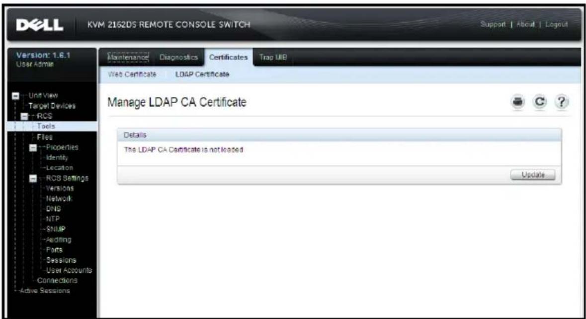
After clicking Update, the following window displays.
Figure 5.9: OBWI - Update LDAP Certificate
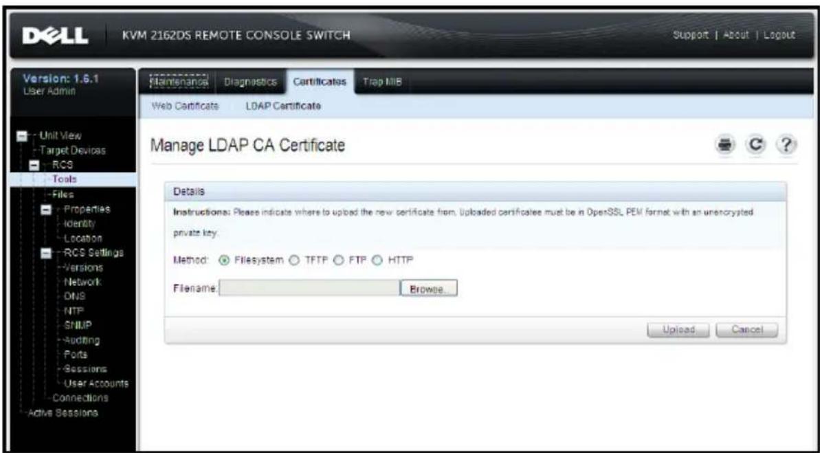
You can browse to a certificate and open it. Once the certificate is open contents are displayed, the user can then send the certificate to the RCS.
Login Timeout
In cases where there is a large enough directory tree to cause LDAP authentication to perform slowly, the Sessions window includes a Login Timeout function with a default timeout of 30 seconds. The login timeout is the time from which the user presses the OK button on the Login dialog until there is no response from the RCS. The RCS will also use this value determine the timeout on a LDAP request for authentication.
To specify the login timeout in the on-board web interface:
1 Click Sessions to open the General Session Settings screen.
2 Specify the number of seconds in the Login Timeout menu.
3 Click Save.
Figure 5.10: OBWI - Login Timeout
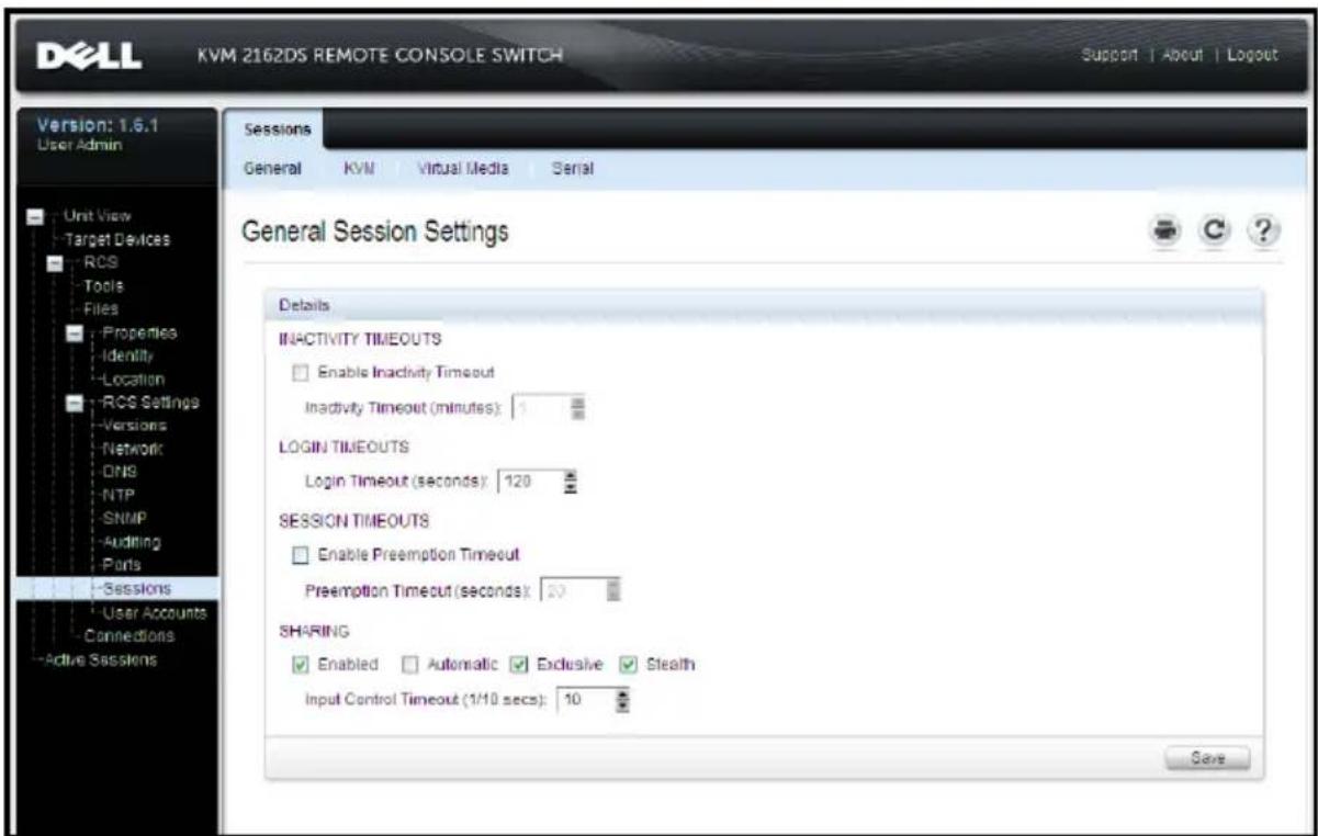

NOTE: The Login Timeout is distinct from the User Login Caching feature. The latter works after a login is completed by caching authorization results for a period of time, eliminating repeated LDAP communications requests.
CA Certificate Information Display
The RCS can only display complete CA Certificate Information in this wind when the public key length is less than or equal to 2048 bits. When the greater than 2048 bits, the subject, issuer, and validity period data in this window will be incomplete.
The following display is an example of the CA certificate information:
1 From the Client, download CA certificate into the RCS.
2 From the serial console Main Menu, type option 8 to display the LDAP CA Certificate.
The RCS will display the following types of information:
Begin CA certificate information display
subject= /DC=msft/DC=ldaptest/CN=MyCertificate
issuer= /DC=msft/DC=ldaptest/CN=MyCertificate
notBefore=Dec 7 20:09:56 2005 GMT
notAfter=Dec 7 20:18:34 2010 GMT
serial=7BA146C0221A08B447B989292074329F
MD5 Fingerprint=
CB:6D:70:30:31:E5:1B:C0:90:BB:DB:32:B2:C9:D1:5A
End CA certificate information display
Perform the steps in the following instructions for enabling the installation RCS software on Microsoft Windows Server 2003 platforms:
1 Select the Start menu.
2 Right-click on My Computer and select Properties.
3 Select the Advanced tab.
4 Click the Performance Settings button.
5 Select the Data Execution Prevention tab.
6 Select the radio button for Turn on DEP for essential Windows programs and services only
7 Click OK.
8 Click OK again on the System Properties dialog box.
Configuring Group Objects
Access control is applied to a specific Active Directory user account by including that user in the membership of a Group in the Group Container. Group membership must also contain the objects representing the RCS(s) and the SIP(s) the user is allowed to access. The level of access granted is determined by the value of a specific attribute in the Group object (Standar Schema) or Association Object (Extended Schema). There are three permission levels available. In increasing order of access they are KVM User, KVM User Admin, and the most powerful level, KVM Appliance Admin.

NOTE: If the KVM User access level is not being used, SIP objects will not need configuration as both administrator permissions have access to all SIPs by default.
| Operation | KVM Appliance Admin | KVM User Admin KVM User |
| Preemption | Allowed to preempt another KVM Appliance Admin or a KVM User Admin. Permission must be configured for each target device by including the TD in the appropriate Group object in the Directory. | Allowed to preempt another User Admin. Permission must be configured for each target device No by including the target device in the appropriate Group object in the Directory. |
| Configure network parameters and global settings | Yes - Permission must be configured for each RCS by including the RCS in the appropriate Group object in the Directory. | No No |
| Restart | Yes - Permission must be configured for each RCS by including the RCS in the appropriate Group object in the Directory. | No No |
| FLASH Upgrade | Yes - Permission must be configured for each RCS by including the RCS in the appropriate Group object in the Directory. | No No |
| Administer user accounts | Yes - Permission must be configured for each RCS by including the RCS in the appropriate Group object in the Directory. | Yes - Permission must be configured for each RCS by including the RCS in the appropriate Group object in the Directory. |
| Configure port settings | Yes - Permission must be configured for each RCS by including the RCS in the appropriate Group object in the Directory. | No No |
| Operation | KVM Appliance Admin | KVM User Admin | KVM User |
| Target Device Access | Yes - Permission must be configured for each RCS by including the RCS in the appropriate Group object in the Directory. | Yes - Permission must be configured for each RCS by including the RCS in the appropriate Group object in the Directory. | Yes, if configured by Administrator. Permission must be configured for each target device by including the TD in the appropriate Group object in the Directory. |
Table 5.3: Allowed Operations by Access Level
An AD user account must be configured to receive RCS Administrator (KV Appliance Admin) permission before that account will be allowed to modify the fields in the Authentication Panel. In particular, only an RCS Administrator is allowed to modify the Authentication Settings.
Active Directory Object Overview for Standard Schema
For each of the physical RCSs on the network that you want to integrate Active Directory for Authentication and Authorization, you must create at least one Computer Object to represent it. You will also need to create a common object for each SIP attached to the RCS that will be controlled using the User privilege level. Computer objects representing SIPs are not required for Administrator level groups. Users in the KVM User Group will only have access to SIPs that are also in the KVM User Group. Users with Administrator privileges will have access to all SIPs by default.
To set up the Group Objects for an RCS:
1 If you have not already, create the Organizational Unit that will contain Group Objects related to your switch installation.
2 Within this Organizational Unit, create three group objects to represent user privilege levels. One for KVM Appliance Administrators, KVM User Administrators and KVM Users, respectively.
3 Using the MSADUC tool, open the KVM Appliance Administrator Group Object and select the Notes property. Type the access level ("KVM Appliance Admin") for that group in the Notes field and save. Repeat the step for the other two Group Objects using their respective names.

NOTE: The single syntax for all access control attribute values is:
"[<arbitrary text string> <delimiter>] < privilege level>
[<delimiter> <arbitrary text string>]"
Where: <privilege level> := "KVM User" or "KVM User Admin" or "KVM Appliance Admin"
<delimiter> ::= one or more of any of the following: <newline> or <c/r> or <comma> or <semicolon> or <tab>
<arbitrary text string> is any string of alphanumeric characters and may be the null (i.e., empty) string.
Square brackets indicate optional items; for example, the following template indicates an optional string and delimiter followed by a required privilege level: "[<arbitrary text string> <delimiter>] < privilege level1>"
4 Create a computer object to represent the RCS.
5 Create a computer object for each SIP attached to a server to be access restricted at the KVM User privilege level.
6 Add the computer object that represents the switch to the appropriate group objects.
7 Add user objects to the appropriate group object for their access level.
8 Add the computer objects for the access controlled SIPs to the KVM Use Group.
Dell Extended Schema Active Directory Object Overview
For each of the physical RCSs on the network that you want to integrate Active Directory for Authentication and Authorization, you must create at least one RCS Device Object to represent the physical switch and one Association Object. The Association object is used to link together the users or groups a specific set of privileges to one or more SIPs. This model provides an Administrator maximum flexibility over the different combinations of users, RCS privileges, and SIPs on the Remote Console Switch without adding to much complexity
The RCS Device Object is the link to the RCS for querying Active Direct authentication and authorization. When a RCS is added to the network, the Administrator must configure the RCS and its device object with its Active Directory name so that users can perform authentication and authorization Active Directory. The Administrator will also need to add the Remote Con Switch to at least one Association Object in order for users to authenticat
You can create as many Association Objects as you want, and each Associ Object can be linked to as many users, groups of users, or RCS Device as desired. The users and RCS Device Objects can be members of any d in the enterprise.
However, each Association Object may be linked (or, may link users, group users, or RCS Device Objects) to only one Privilege Object. A Privilege O allows an Administrator to control which users have what kind of privileges specific SIPs.
The following figure illustrates that the Association Object provides the connection that is needed for all of the Authentication and Authorization.
Figure 5.11: Typical Setup for Active Directory Objects
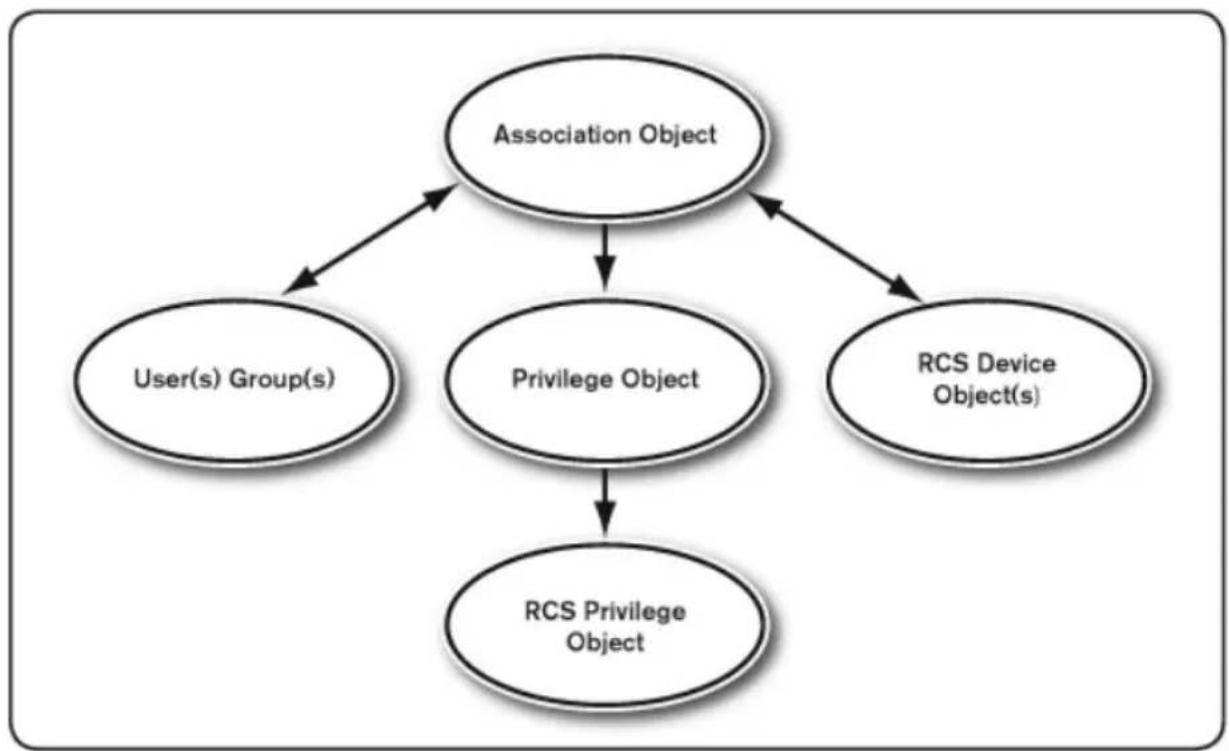
flowchart
graph TD
    A["Association Object"] --> B["User(s) Group(s)"]
    A --> C["Privilege Object"]
    A --> D["RCS Device Object(s)"]
    C --> E["RCS Privilege Object"]
You can create as many or as few association objects as you want or need. However, you must create at least one Association Object, and you must have one RCS Device Object for each RCS on the network that you want to integrate with Active Directory for Authentication and Authorization. The Association Object allows for as many or as few users and/or groups as well RCS Device Objects. However, the Association Object only has one Privilege Object per Association Object. The Association Object connects the users who have privileges on the RCSs.
In addition, you can set up Active Directory objects in a single domain or multiple domains. For example, you have two RCSs (RCS1 and RCS2) and three existing Active Directory users (User1, User2, and User3). You want to give User1 and User2 an Administrator privilege to both RCSs and give User login privilege to the RCS2.
The following figure illustrates how to set up the Active Directory objects in this scenario.
Figure 5.12: Setting Up Active Directory Objects in a Single Domain
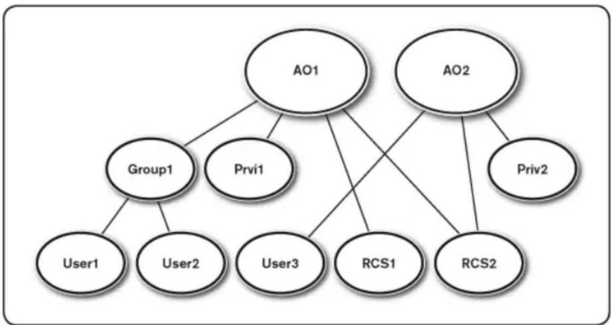
flowchart
graph TD
    A["AO1"] --> B["Group1"]
    A --> C["Prvi1"]
    A --> D["AO2"]
    B --> E["User1"]
    B --> F["User2"]
    B --> G["User3"]
    C --> H["RCS1"]
    C --> I["RCS2"]
    D --> J["Priv2"]
To set up the objects for the single domain scenario, perform the followir tasks:
1 Create two Association Objects.
2 Create two RCS Device Objects, RCS1 and RCS2, to represent the two RCSs.
3 Create two Privilege Objects, Priv1 and Priv2, in which Priv1 has all privileges (Administrator) and Priv2 has login privileges.
4 Group User1 and User2 into Group1.
5 Add Group1 as Members in Association Object 1 (AO1), Priv1 as Privil Objects in AO1, and RCS1 and RCS2 as RCS Devices in AO1.
6 Add User3 as Members in Association Object 2 (AO2), Priv2 as Privileg Objects in AO2, and RCS2 as RCS Devices in AO2.
See “Adding RCS Users and Privileges to Active Directory with Dell Schen Extensions” for detailed instructions.
The following figure illustrates how you can set up the Active Directory Obj in multiple domains. In this scenario, you have two RCSs (RCS1 and RCS2) and three existing Active Directory users (User1, User2, and User3).
User1 is in Domain1, and User2 and User3 are in Domain2. You want to User1 and User2 an administrator privilege to both RCSs and give User3 a privilege to the RCS2.
Figure 5.13: Setting Up Active Directory Objects in Multiple Domains
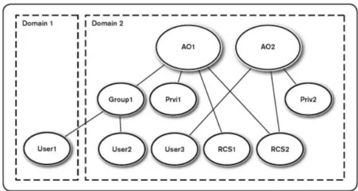
flowchart
graph TD
    subgraph Domain 1
        User1["User1"]
    end
    subgraph Domain 2
        Group1["Group1"]
        Prvi1["Prvi1"]
        User2["User2"]
        User3["User3"]
        RCS1["RCS1"]
        RCS2["RCS2"]
    end
    A01["AO1"] --> Group1
    A01 --> Prvi1
    A01 --> User2
    A01 --> User3
    A01 --> RCS1
    A01 --> RCS2
    A02["AO2"] --> Group1
    A02 --> Prvi1
    A02 --> User3
    A02 --> RCS1
    A02 --> RCS2
    A02 --> RCS2
    Subgraph Domain 2
        OA1
        OA2
    end
To set up the objects for the multiple domain scenario, perform the followir tasks:
1 Ensure that the domain forest function is in Native or Windows 2003 mode.
2 Create two Association Objects, AO1 (of Universal scope) and AO2, in an domain. The figure shows the objects in Domain2.
3 Create two RCS Device Objects, RCS1 and RCS2, to represent the two RCSs.
4 Create two Privilege Objects, Priv1 and Priv2, in which Priv1 has all privileges (Administrator) and Priv2 has login privileges.
5 Group User1 and User2 into Group1. The group scope of Group1 must Universal.
6 Add Group1 as Members in Association Object 1 (AO1), Priv1 as Privil Objects in AO1, and RCS1, RCS2 as RCS Devices in AO1.
7 Add User3 as a Member in Association Object 2 (AO2), Priv2 as Privil Objects in AO2, and RCS2 as RCS Devices in AO2.
Configuring Active Directory with Dell Schema Extensions to Access Your RCS
Before you can use Active Directory to access your RCS, you must configure Active Directory software and the Remote Console Switch by performing the following steps in their numbered order:
1 Extend the Active Directory schema.
2 Extend the Active Directory Users and Computers Snap-in.
3 Add RCS users and their privileges to Active Directory.
Extending the Active Directory Schema (Optional)
Extending your Active Directory schema will add a Dell organizational unit, schema classes and attributes, and example privileges and association objects the Active Directory schema.

NOTE: Before you extend the schema, you must have Schema Admin privileges on the Schema Master Flexible Single Master Operation (FSMO) Role Owner of the domain forest.
You can extend your schema using two different methods. You can use the Schema Extender utility or you can use the LDIF script file.

NOTE: The Dell organizational unit will not be added if you use the LDIF script file.
The LDIF files and Dell Schema Extender can be obtained at dell.com/suppc. To use the LDIF files, see the instructions in the readme that is in the I files directory. To use the Dell Schema Extender to extend the Active Direc Schema, perform the steps in “Using the Dell Schema Extender.”
You can copy and run the Schema Extender or LDIF files from any locatio Using the Dell Schema Extender

NOTE: The Dell Schema Extender uses the SchemaExtenderOem.ini file. To ensure that the Dell Schema Extender utility functions properly, do not modify the name of this file.
1 Click Next on the Welcome screen.
2 Read the warning and click Next again.
3 Either select Use Current Log In Credentials or enter a user name and password with schema administrator rights.
4 Click Next to run the Dell Schema Extender.
5 Click Finish.
Installing the Dell Extension to the Active Directory Users and Computers Snap-In (Optional)
When you extend the schema in Active Directory, you must also extend the Active Directory Users and Computers snap-in so that the administrator can manage RCS devices, Users and User Groups, RCS Associations, and SIP Privileges. The Dell Extension to the Active Directory User's and Computers Snap-In is an option that can be installed when you install your systems management software using the Dell Systems Management Consoles CD. See the Dell OpenManage Software Quick Installation Guide for further instruction on installing systems management software.

NOTE: You must install the Administrator Pack on each system that is managing the Active Directory RCS Objects. The installation is described in the following section, "Opening the Active Directory Users and Computers Snap-In." If you do not install the Administrator Pack, then you cannot view the Dell SIP Object in the container.

NOTE: For more information about the Active Directory Users and Computers snap-in, see your Microsoft documentation.
Opening the Active Directory Users and Computers Snap-In
To open the Active Directory Users and Computers snap-in, perform the following steps:
If you are on the domain controller, click Start -Admin Tools - Active Users and Computers
- Or -
If you are not on the domain controller, you must have the appropriate Microsoft Administrator Pack installed on your local system. To install this Administrator Pack, click Start - Run, type
1 Click File (or Console on systems running Windows 2000) in the Console 1 window.
2 Click Add/Remove Snap-in.
3 Select the Active Directory Users and Computers snap-in and click Add
4 Click Close and click OK.
Adding Users and Privileges to Active Directory with Dell Schema Extensions
The Dell-extended Active Directory Users and Computers snap-in allows you add RCS users and privileges by creating SIP, Association, and Privilege ob To add each type of object, perform the steps in each subsections.
Creating a SIP Object
1 In the MMC Console Root window, right-click a container.
2 Select New - Dell SIP Object. This opens the New Object window.
3 Type a name for the new object. This name must match the RCS name that you will type in step 4 of "Configuring the Remote Console Switch page 38.
4 Select SIP Device Object.
5 Click OK.
Creating a Privilege Object
Privilege Objects must be created in the same domain as the Association Of to which it is associated.
1 In the Console Root (MMC) window, right-click a container.
2 Select New - Dell SIP Object to open the New Object window.
3 Type a name for the new object.
4 Select Privilege Object.
5 Click OK.
6 Right-click the privilege object that you created, and select Properties.
7 Click the RCS Privileges tab and select the RCS privileges that you want the user to have.
Using Dell Association Objects Syntax
Using the Dell Association Objects syntax, object types default to User and Group in the Dell LDAP Schema. In the Dell Extended Schema, Dell has unique Object IDs for four new object classes:
• KVM RCS Objects
- KVM SIP Objects
- Privilege Objects
- Association Objects
Each of these new object classes is defined in terms of various combinations (hierarchies) of default Active Directory classes, together with Dell unique attribute types. Each of the Dell unique attribute types is defined in terms: default Active Directory attribute syntax.
The default Microsoft Active Directory object classes used include User and Group. The User class generally denotes Active Directory objects that contain information about single entities. The Group class represents containers used nesting and contain information about collections of objects.
Each KVM RCS Object represents an individual Remote Console Switch with Active Directory. Since these are single entities, in the LDAP default language they are User objects rather than Group objects.
Each Privilege Object defines a distinct composite set of privileges. Each so treated as a discrete entity, therefore it is a User object rather than a G object.
An Association Object contains a collection of information about the private granted to specific user accounts with respect to a specific RCS(s) and/or specific SIP(s). User accounts in an RCS Object may be specified in term any combination of the following:
- Individual account
• Active Directory security group of user accounts
- Multiple Active Directory security groups of user accounts
Similarly, for the RCSs and/or SIPs in an Association Object and because the Association Object has the ability to use security groups in the same way, i defined as a group object itself.
Creating an Association Object
The Association Object is derived from a Group and must contain a Group Type. The Association Scope specifies the Security Group Type for the Association Object. When you create an Association Object, you must choose the Association Scope that applies to the type of objects you intend to add Selecting Universal, for example, means that association objects are only available when the Active Directory Domain is functioning in Native Mode of above.
To create an association object:
1 In the Console Root (MMC) window, right-click a container.
2 Select New - Dell SIP Object to open the New Object window.
3 Type a name for the new object.
4 Select Association Object.
5 Select the scope for the Association Object.
6 Click OK.
Adding Objects to an Association Object
By using the Association Object Properties window, you can associate users or user groups, privilege objects, and SIP devices or SIP device groups.

NOTE: When using Windows 2000 mode or higher, you must use Universal Groups to span domains with your users or SIP objects.
You can add groups of Users and SIP devices. Creating Dell-related groups i done the same way you create other groups.
To add users or User Groups:
1 Right-click the Association Object and select Properties.
2 Select the Users tab and click Add.
3 Type the user or User Group name and click OK.
Click the Privilege Object tab to add the privilege object to the association defines the user's or user group's privileges when authenticating to a SIP

NOTE: You can add only one privilege object to an association object.
To add a privilege:
1 Select the Privileges Object tab and click Add.
2 Type the Privilege Object name and click OK.
Click the Products tab to add one or more SIP devices to the association associated devices specify the SIP devices connected to the network that are available for the defined users or user groups.

NOTE: You can add multiple SIP devices to an association object.
To add SIP devices or SIP device groups:
1 Select the Products tab and click Add.
2 Type the SIP device or SIP device group name and click OK.
3 In the Properties window, click Apply and then OK.
Console Redirection Access Security
In any RCS installation, any user privilege allows the user to launch the web interface. The on-board web interface functionality for that user is lim by the User Privilege level established in the RCS. LDAP with Dell Exten Schema adds an extra level of security to RCS management by allowing administrators to limit a user's access to the on-board web interface.
Authorization to use the on-board web interface is defined by whether Use Privilege level is or is not configured in the KVM RCS Privileges tab of Privilege Object (DPO). The Console Redirection Access checkbox in the K
SIP Privileges tab of the DPO provides the means for a user who cannot have the on-board web interface to launch Video Viewer sessions to a subset of SIP through the RCS Client. This authorization is controlled by a combination of the configuration parameters set in the DPO and the SIP Objects contained in the Dell Association Object (DAO).
If you do not wish a user to have authorization to access the on-board we interface, but you do wish them to be able to launch viewer sessions from RCS Client, perform the following steps:
1 Create a Dell SIP object for each SIP that the User(s) is (are) allowed access.
2 Create an Active Directory User account for each of the users to be controlled.
3 Create a DPO. Do not check any of the three boxes on the KVM RCS Privileges tab. Check the Console Redirection Access box on the KVM SI Privileges tab.

NOTE: If you check any of the KVM RCS Privileges checkboxes and you check the Console Redirection Access box, the normal User Privileges associated with the privilege level checked in the KVM RCS Privileges box will take precedence over the Console Redirection Access checkbox, and the user will still be able to view the AMP.
4 Create a DAO.
5 Open the properties dialog for the DAO created in step 4.
a. Add all the user accounts created in step 2.
b. Add the DPO created in step 3.
c. Add the SIP objects created in step 1.
Using Active Directory to Log In to the RCS
You can use Active Directory to log in to the RCS through the RCS softw OBWI.
The login syntax is consistent for all three methods:
username@domain or

NOTE: You cannot specify NetBIOS domain names, such as Americas, since those names cannot be resolved.

NOTE: If a domain name is not included, the local database in the Remote Console Switch will be used to authenticate the user.
Target Device Naming Requirements for LDAP Implementation
If you experience the following error:
Login Failure. Reason: Access cannot be granted due to Authentication Serv errors
Please verify that the SIP object was created in the Active Directory and name exactly matches the name assigned to that SIP via the OBWI at the console switch.
The Dell Standard Schema and the Dell Extended Schema use specific object classes in the Microsoft Windows Active Directory to represent SIPs. The Microsoft standard naming conventions for these object classes prohibit the use of special characters or spaces. If you intend to use LDAP in a deployed environment where target device names in SIPs currently include spaces or special characters, you will need to rename them without spaces or special characters.
Renaming a target device in a SIP should be done through the OBWI at console switch and then resynchronized through the RCS software. It is important to note that while the OBWI will allow you to enter spaces in names assigned to the SIPs, Active Directory does not. You must name S objects according to the Microsoft Active Directory rules.
Frequently Asked Questions
The following table lists frequently asked questions and answers.
| Can I log into the Remote Console Switch using Active Directory across multiple forests? | The RCS Active Directory query algorithm only supports a single tree in a single forest. |
| Does the login to the Remote Console Switch using Active Directory work in mixed mode (that is, the domain controllers in the forest run different operating systems, such as Microsoft Windows NT® 4.0, Windows 2000, or Windows Server 2003)? | Yes. In mixed mode, all objects used by the RCS querying process (among user, SIP Device Object, and Association Object) have to be in the same domain. The Dell-extended Active Directory Users and Computers snap-in checks the mode and limits users in order to create objects across domains if in mixed mode. |
| Does using the RCS with Active Directory support multiple domain environments? | Yes. The domain forest function level must be in Native mode or Windows 2003 mode. In addition, the groups among Association Object, Remote Console Switch user objects, and SIP Device Objects (including Association Object) must be universal groups. |
| Can these Dell-extended objects (Dell Association Object, Dell Remote Console Switch Device, and Dell Privilege Object) be in different domains? | The Association Object and the Privilege Object must be in the same domain. The Dell-extended Active Directory Users and Computers snap-in forces you to create these two objects in the same domain. Other objects can be in different domains. |
| Are there any restrictions on Domain Controller SSL configuration? | Yes. All Active Directory servers’ SSL certificates in the forest must be signed by the same root CA since RCS only allows uploading one trusted CA SSL certificate. |
What can I do if I cannot log into the RCS using Active Directory authentication? How do I troubleshoot the issue?
Troubleshoot as follows:
- If no domain name is specified, the local database is used. To login when AD authentication isn't working, use the default local admin account.
- Ensure that you have checked the Enable Active Directory checkbox (RCS Software) or the Use LDAP Authentication checkbox (on-board web interface) on the RCS Active Directory configuration page.
- Ensure that the DNS setting is correct on the RCS Networking configuration page.
- Ensure Network Time Protocol is enabled on at least one server specified on the NTP panel.
- Ensure that you have uploaded the Active Directory certificate from your Active Directory root CA to the RCS.
- Check the Domain Controller SSL certificates to ensure that they have not expired.
- Ensure that your “Remote Console Switch Name”, “Root Domain Name”, and “RCS Domain Name” match your Active Directory environment configuration.
- Ensure that you use the correct user domain name during a login and not the NetBIOS name.
Appendix A: Terminal Operations
Each RCS may be configured at the switch level through the Console me interface accessed through the SETUP port. All terminal commands are acc through a terminal or PC running terminal emulation software.

NOTE: The preferred method is to make all configuration settings in the local UI.
To connect a terminal to the switch:
1 Using the supplied RJ-45 to DB-9 (female) adaptor and flat RJ-45 cable connect a terminal or a PC that is running terminal emulation software (such as HyperTerminal) to the SETUP port on the back panel of the switch. The terminal settings are 9600 bits per second (bps), 8 bits, 1 bit, no parity and no flow control.
2 Turn on each target device and then turn on the switch. When the s completes initialization, the Console menu will display the following message: Press any key to continue.
Console Boot Menu Options
While the switch is turning on, you can press a key to view the boot r From this menu, you can choose one of four options.
- Boot Normal
- Boot Alternate Firmware
- Reset Factory Defaults
• Full-Factory Reset
Console Main Menu Options
Once turned on, the main menu displays the product name and version. From this menu, you can choose one of four options.
- Network configuration: This menu option allows you to configure the network setting of the RCS.
- Debug messages: This menu option turns on console status messages. Because this can significantly reduce performance, you should only enable debug messages when instructed to do so by Dell Technical Support. When you are finished viewing the messages, press any key to exit this mode.
- Reset RCS: This menu option allows you to execute a soft reset of the switch.
- Exit: This menu selection will return you to the ready prompt. If the Console menu interface password is enabled, you must exit the Console main menu so that the next user will be prompted with the Username Password login screen.
Appendix B: Using SIPs
An administrator can choose between the Avocent ACS console server and Cisco pinouts for each serial SIP port via the local user interface or the OBWI. ACS is the default.
To change the pinout to Cisco mode:
1 Select Unit View - RCS - RCS Settings - Ports - SIPs.
2 Click on the desired SIP.
3 Select Settings - Pinout.

NOTE: If the DB-9 adaptor is used, select the ACS console server pinouts.
ACS Console Server Port Pinouts
The following table lists the ACS console server serial port pinouts for the
Table B.1: ACS Console Server Serial Port Pinouts
| Pin No. | Signal Name | Input/Output |
| 1 | RTS - Request to Send | OUT |
| 2 | DTR - Data Terminal Ready | OUT |
| 3 | TXD - Transmit Data | OUT |
| 4 | GND - Signal Ground | N/A |
| 5 | CTS - Clear to Send | IN |
| Pin No. Signal Name Input/Output |
| 6 RXD - Receive Data IN |
| 7 DCD/DSR - Data Set Ready IN |
| 8 N/C - Not Connected N/A |
Cisco Port Pinouts
The following table lists the Cisco serial port pinouts for the SIPs.
Table B.2: Cisco Serial Port Pinouts
| Pin No. Signal Name | Input/Output |
| 1 CTS - Clear to Send | IN |
| 2 DCD/DSR - Data Set Ready | IN |
| 3 RXD - Receive Data | IN |
| 4 GND - Signal Ground | N/A |
| 5 N/C - Not Connected | N/A |
| 6 TXD - Transmit Data | OUT |
| 7 DTR - Data Terminal Ready | OUT |
| 8 RTS - Request to Send | OUT |
Appendix C: MIB and SNMP Traps
The Dell RCS has the ability to send audit events to an SNMP Manager SNMP traps are defined in an SNMP Trap MIB.
The Trap MIB file may be uploaded from the RCS using the Save Trap function. The uploaded Trap MIB file may then be loaded into an SNMP Receiver application.
Audit events may also be directed to “syslog” destinations. The format of syslog message is given in the corresponding “--#SUMMARY” comment of a trap defined in the Trap MIB file.
This appendix describes the trap events which the RCS may generate. Although care has been taken to keep the information in this appendix up to date Trap MIB file will contain the most accurate trap information.
An SNMP manager may access MIB-II objects of the RCS using the IPv4 IPv6 protocols.
By design, the enterprise specific MIB objects within the RCS cannot be accessed using SNMP.
The RCS Trap definitions use the structure described in the following Req For Comments (RFCs).
- RFC-1155-SMI
Describes the common structures and identification scheme for the definition of management information for use with TCP/IP-based Internets.
- RFC-1212
Describes the format for producing concise and descriptive MIB modules.
- RFC-1213-MIB
Describes the Internet standard MIB-II for use with network management protocols in TCP/IP-based inter-networks.
- RFC-1215
Describes the SNMP standardized traps and provides a means for defining enterprise-specific traps. The specific objects reported by each trap are defined in the Trap MIB file which is uploaded from the RCS. The following table is a list of the generated trap events.
Table C.1: Generated Trap Events
| Trap Event Trap Number | |
| Reboot Started 1 | |
| User Login 2 | |
| User Logout 3 | |
| Target Session Started 4 | |
| Target Session Stopped 5 | |
| Target Session Terminated 6 | |
| traps 7 through 9 are deprecated | 7-9 |
| Image File Upgrade Started | 10 |
| Image File Upgrade Results | 11 |
| User Added | 12 |
| User Deleted 13 | |
| User Modified 14 | |
| User Locked 15 | |
| User Unlocked 16 | |
| User Authentication Failure 17 | |
| SIP Added 18 | |
| SIP Removed 19 | |
| SIP Moved 20 | |
| Target Device Name Changed | 21 |
| Tiered Switch Added | 22 |
| Tiered Switch Removed | 23 |
| Tiered Switch Name Changed | 24 |
| Configuration File Loaded | 25 |
| User Database File Loaded | 26 |
| Ca Certificate Loaded | 27 |
| SIP Image Upgrade Started | 28 |
| SIP Image Upgrade Result | 29 |
| SIP Restarted 30 | |
| Virtual Media Session Started | 31 |
| Virtual Media Session Stopped 32 | |
| Virtual Media Session Terminated 33 | |
| Virtual Media Session Reserved 34 | |
| Virtual Media Session Unreserved 35 | |
| Virtual Media Drive Mapped 36 | |
| Virtual Media Drive Unmapped 37 | |
| traps 38 through 44 are deprecated 38-44 | |
| Screen Resolution Changed 45 | |
| Aggregated Target Device Status Changed 46 | |
| Factory Defaults Set | 47 |
| Power Supply Failure | 48 |
| Power Supply Restored | 49 |
| Pdu Device Online | 50 |
| Pdu Device Offline | 51 |
| Pdu Socket On Command | 52 |
| Pdu Socket Off Command | 53 |
| Pdu Socket Reboot Command | 54 |
| Pdu Socket On Sense Fail | 55 |
| Pdu Socket Off Sense Fail | 56 |
| Pdu Status Socket On 57 | |
| Pdu Status Socket Off 58 | |
| Pdu Port Name Changed 59 | |
| Pdu Socket Name Changed 60 | |
| Pdu Input Feed Total Load High 61 | |
| Pdu Input Feed Total Load Low 62 | |
| Pdu Device Name Changed 63 | |
| Pdu Input Feed Name Changed 64 | |
| Pdu Socket Lock Command 65 | |
| Pdu Socket Unlock Command | 66 |
| Pdu Status Socket Lock | 67 |
| Pdu Status Socket Unlock | 68 |
| Pdu Image File Upgrade Started | 69 |
| Pdu Image File Upgrade Result | 70 |
| Pdu Circuit Name Changed | 71 |
| Pdu Device Total Load High 72 | |
| Pdu Circuit Total Load High | 73 |
| Pdu Socket Total Load High 74 | |
| Fan Failure | 75 |
| Trap Event Trap Number |
| Temperature Range 76 |
| Smart Card Inserted 77 |
| Smart Card Removed 78 |
Appendix D: Cable Pinouts Information

NOTE: All switches have the 8-pin modular jack for the modem and console/setup ports.
Modem Pinouts
The modem port pinouts and descriptions are provided in the following fig and table.
Figure D.1: Modem Pinouts
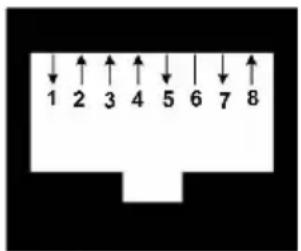
Table D.1: Modem Pinout Descriptions
| Pin Number | Description Pin Number Description | |
| 1 | Request to Send (RTS 5) | Transmit Data (TXD) |
| 2 | Data Set Ready (DSR 6) | Signal Ground (SG) |
| Pin Number | Description Pin Number Description | ||
| 3 | Data Carrier Detect (DCD) | 7 | Data Terminal Ready (DTR) |
| 4 Receive Data (RXD 8 | Clear to Send (CTS | ||
Console/Setup Pinouts
The console/setup port pinouts and descriptions are provided in the following figure and table.
Figure D.2: Console/Setup Pinouts
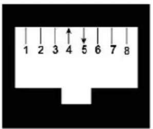
Table D.2: Console/Setup Pinout Descriptions
| Pin Number | Description Pin Number | Description | |
| 1 | No Connection | 5 | Transmit Data (TXD) |
| 2 | No Connection | 6 | Signal Ground (SG) |
| 3 | No Connection | 7 | No Connection |
| 4 | Receive Data (RXD) | 8 | No Connection |
Appendix E: UTP Cabling
This appendix discusses various aspects of connection media. The RCS system utilizes UTP cabling. The performance of an switch system depends on high quality connections. Poor quality or poorly installed or maintained cabling can diminish switch system performance.

NOTE: This appendix is for information purposes only. Please consult with your local code officials and/or cabling consultants prior to any installation.
UTP Copper Cabling
The following are basic definitions for the three types of UTP cabling that RCS supports.
- CAT 5 (4-pair) high performance cable consists of twisted pair conducto used primarily for data transmission. The twisting of the pairs gives this cable some immunity from the infiltration of unwanted interference. CA' cable is generally used for networks running at 10 or 100 Mbps.
- CAT 5E (enhanced) cable has the same characteristics as CAT 5, but manufactured to somewhat more stringent standards.
- CAT 6 cable is manufactured to tighter requirements than CAT 5E cable. CAT 6 has higher measured frequency ranges and significantly better performance requirements than CAT 5E cable at the same frequencies.
Wiring Standards
There are two supported wiring standards for 8-conductor (4-pair) RJ-45 terminated UTP cable: EIA/TIA 568A and B. These standards apply to
installations utilizing UTP cable specifications. The RCS system supports either of these wiring standards. The following table describes the standards for each pin.
Table E.1: UTP wiring standards
| Pin EIA/TIA 568A EIA/TIA 568B | |
| 1 white/green white/orange | |
| 2 green orange | |
| 3 white/orange white/green | |
| 4 blue blue | |
| 5 white/blue white/blue | |
| 6 orange | green |
| 7 white/brown | white/brown |
| 8 brown | brown |
Cabling Installation, Maintenance, and Safety Tips
The following is a list of important safety considerations that should be reviewed prior to installing or maintaining your cables:
- Keep all UTP runs to a maximum of 30 feet each.
-
Maintain the twists of the pairs all the way to the point of termination no more than one-half inch untwisted. Do not skin off more than one of the jacket while terminating.
-
If bending the cable is necessary, make it gradual with no bend sharpe a one inch radius. Allowing the cable to be sharply bent or kinked ca permanently damage the cable's interior.
- Dress the cables neatly with cable ties, using low to moderate pressure. not over tighten the ties.
- Cross-connect cables where necessary, using rated punch blocks, patch panels, and components. Do not splice or bridge the cable at any point
- Keep the UTP cable as far away as possible from potential sources of such as electrical cables, transformers, and light fixtures. Do not tie the cables to electrical conduits or lay the cables on electrical fixtures.
- Always test every installed segment with a cable tester. Toning alone is an acceptable test.
- Always install jacks so as to prevent dust and other contaminants from settling on the contacts. The contacts of the jack should face up on flush mounted plates, or left/right/down on surface mount boxes.
- Always leave extra slack on the cables, neatly coiled in the ceiling or a concealed location. Leave at least five feet at the work outlet side and feet at the patch panel side.
- Choose either 568A or 568B wiring standard before beginning. Wire all jacks and patch panels for the same wiring scheme. Do not mix 568A 568B wiring in the same installation.
- Always obey all local and national fire and building codes. Be sure to all the cables that penetrate a firewall. Use plenum-rated cable where i required.
Appendix F: Sun Advanced Key Emulation
Certain keys on a standard Type 5 (US) Sun keyboard can be emulated press sequences on the local port USB keyboard. To enable Sun Advanced Emulation mode and use these keys, press and hold
These key combinations will work with the Dell USB, USB2, and USB2+C SIPs and Avocent USB, USB2, and VMC IQ modules. With the exception
Table F.1: Sun Key Emulation
| Compose Application | 1 |
| Compose keypad | |
| Power F11 | |
| Open F7 | |
| Help Num Lock | |
| Props F3 | |
| Front F5 | |
| Stop F1 | |
| Again F2 | |
| Undo F4 | |
| Cut F10 | |
| Copy F6 | |
| Paste F8 | |
| Find F9 | |
| Mute keypad / | |
| Vol.+ keypad + | |
| Vol.- | keypad - |
| Command (left) ^2 | F12 |
| Command (left) ^2 | Win (GUI) left ^1 |
| Command (right) ^2 | Win (GUI) right ^1 |
ENDNOTES:
(1) Windows 95 104-key keyboard.
(2) The Command key is the Sun Meta (diamond) key.
Appendix G: Technical Specifications
Table G.1: RCS Technical Specifications
| 1082DS: 8 | |
| Number of ports | 2162DS: 16 |
| 4322DS: 32 | |
| Type | Dell PS/2, USB, USB2, USB2+CAC, and Serial SIPs. Avocent PS/2, PS2M, USB, Sun, USB2, VMC, and Serial modules. |
| Connectors 8-pin modular (RJ-45) | |
| Sync types Separate horizontal and vertical | |
| Input video resolution | Standard640 x 480 @ 60 Hz800 x 600 @ 75 Hz960 x 700 @ 75 Hz1024 x 768 @ 75 Hz1280 x 1024 @ 75 Hz1600 x 1200 @ 60 HzWidescreen800 x 500 @ 60 Hz1024 x 640 @ 60 Hz1280 x 800 @ 60 Hz1440 x 900 @ 60 Hz1680 x 1050 @ 60 Hz |
| Supported cabling | 4-pair UTP, 45 meters maximum length |
| Dimensions | |
| Form factor 1U or 0U rack mount | |
| Dimensions 1.72 x 17.00 x 9.20 (Height x Width x Depth) | |
| Weight (without cables) | 1082DS: 6.6 lb (3.0 kg)2162DS: 7.0 lb (3.2 kg)4322DS: 7.6 lb (3.4 kg) |
| SETUP port | |
| Number 1 | |
| Protocol RS-232 serial | |
| Connector 8-pin modular (RJ-45) | |
| Local port | |
| Number/Type 1 VGA/4 USB | |
| Network connection | |
| Number 2 | |
| Protocol 10/100/1000 Ethernet | |
| Connector 8-pin modular (RJ-45) | |
| USB device port | |
| Number 4 | |
| Protocol USB 2.0 | |
| MODEM port | |
| Number 1 | |
| Protocol RS-232 serial | |
| Connectors 8-pin modular (RJ-45) | |
| PDU port | |
| Number 2 | |
| Protocol RS-232 serial | |
| Connector 8-pin modular (RJ-45) | |
| Power specifications | |
| Connectors | 1082DS: 1 IEC C14 |
| 2162DS: 2 IEC C14 | |
| 4322DS: 2 IEC C14 | |
| Type Internal | |
| Power 18W | |
| Heat dissipation 47 BTU/hr | |
| AC input range 100 - 240 VAC | |
| AC frequency 50/60 Hz auto-sensing | |
| AC input current rating | 1.25 A |
| AC input power (maximum) | 40 W |
| Ambient atmospheric condition ratings | |
| Temperature | 32 to 122 degrees Fahrenheit (0 to 50 degrees Celsius) operating; -4 to 158 degrees Fahrenheit (-20 to 70 degrees Celsius) non-operating |
| Humidity | Operating: 20% to 80 % relative humidity (non-condensing Non-operating: 5% to 95% relative humidity, 38.7 degrees C maximum wet bulb temperature |
| Safety and EMC Standards approvals and markings | UL / cUL, CE - EU, N (Nemko), GOST, C-Tick, NOM / NYCE, MIC (KCC), SASO, TUV-GS, IRAM, FCC, ICES, VCCI, SoNCAP, SABS, Bellis, FIS/ Kvalitet, Koncar, INSM, Ukrtest, STZ, KUCASSafety certifications and EMC certifications for this product are obtained under one or more of the following designations: CMN (Certification Model Number), MPN (Manufacturer's Part Number), or Sales Level Model designation. The designation that is referenced in the EMC and/or safety reports and certificates are printed on the label applied to this product. |
Appendix H: Technical Support
Our Technical Support staff is ready to assist you with any installation or operating issues you encounter with your Dell product. If an issue should develop, follow the steps below for the fastest possible service.
To resolve an issue:
1 Check the pertinent section of this manual to see if the issue can be resolved by following the procedures outlined.
2 Check our web site at dell.com/support to search the knowledge base of the on-line service request.
3 Call the Dell Technical Support location nearest you.
- Notes, Cautions, and Warnings
- Contents
- Product Overview 1
- The Video Viewer Window 81
- LDAP Feature for the RCS 105
- Product Overview
- Features and Benefits
- Reduce Cable Bulk
- KVM Switching Capabilities
- Multiplatform Support
- True Serial Capabilities
- Local and Remote User Interfaces
- Virtual Media and Smart Card-capable Switches
- On-board Web Interface
- Access the Switch Using a Standard TCP/IP Network
- Encryption
- Video
- Flash Upgradeable
- Tier Expansion
- Avocent Management Software Plug-in
- FIPS cryptographic module
- Sample Configuration
- Safety Precautions
- General
- LAN Options
- Installation
- RCS Quick Setup
- Getting Started
- Setting up Your Network
- Keyboards
- Rack Mounting the RCS
- Rack Mounting Safety Considerations
- Installing the Dell ReadyRails™ System
- 1U Tool-less Configuration (Four-post Square Hole or Unthreaded Round Hole)
- Two-post Flush-mount Configuration
- Two-post Center-mount Configuration
- Four-post Threaded Configuration
- Installing the RCS
- 1U Rear-rack Installation
- 1U Front-rack Installation
- 0U RCS Installation
- Connecting the RCS Hardware
- Connecting a SIP
- Adding a Tiered Switch
- Cascading with Legacy Switches
- Number Description
- Adding a PEM (Optional)
- Configuring the Remote Console Switch
- Setting up the Built-in Web Server
- Connecting to the OBWI Through a Firewall
- Verifying the Connections
- Rear Panel Ethernet Connection LEDs
- Rear Panel Power Status LEDs
- Adjusting Mouse Settings on Target Devices
- Local and Remote Configuration
- Local User Interface (UI)
- Filtering
- OBWI
- Using the User Interfaces
- Launching a Session
- Scan Mode
- Click Save.
- Viewing System Information
- RCS Tools
- Rebooting the RCS
- Upgrading RCS Firmware
- Saving and Restoring RCS Configurations and RCS User Databases
- Network Settings
- DNS Settings
- NTP Settings
- SNMP Settings
- Auditing Event Settings
- Setting Event Destinations
- Ports - Configuring SIPs
- Upgrading SIPs
- Power Device Settings
- Associated Target Servers and Power Outlets
- Grouping Power Outlets
- Default Outlet Names
- Assigning an Outlet Name
- Access Control Inheritance
- Renaming of a Target Device
- Prioritized Status of Target Devices
- Local Session Page on the Local Port
- Local Port UI Settings
- Modem Settings
- Setup Settings - Port Security
- Sessions
- Configuring General Sessions
- Configuring KVM Sessions
- Configuring Local Virtual Media Sessions
- Virtual Media Options
- Local Users
- Configuring Serial Sessions
- Setting Up User Accounts
- Managing Local Accounts
- Access Levels
- Avocent Management Software Device IP Addresses
- LDAP
- Override Admin
- Active Sessions
- Closing a Session
- The Video Viewer Window
- Changing the Toolbar
- Session Time-out
- Window Size
- Adjusting the View
- Refreshing the Image
- Video Settings
- Additional Video Adjustment
- Target Video Settings
- Automatic Video Adjustment
- Video Test Pattern
- Vendor-specific Video Settings
- Color Settings
- Adjusting Color Depth
- Contrast and Brightness
- Noise Settings
- Detection Thresholds
- Mouse Settings
- Adjusting Mouse Options
- Cursor Type
- Mouse Scaling
- Mouse Alignment and Synchronization
- Virtual Media
- Requirements
- Sharing and Preemption Considerations
- Virtual Media Dialog Box
- Opening a Virtual Media Session
- Closing a Virtual Media Session
- Smart Cards
- Keyboard Pass-through
- Macros
- Saving the View
- LDAP Feature for the RCS
- The Structure of Active Directory
- Domain Controller Computers
- Object Classes
- Attributes
- Schema Extensions
- Standard Schema versus Dell Extended Schema
- Standard Installation
- Configure the Override Admin Account
- Configuring DNS Settings
- Configuring the Network Time Protocol (NTP) Settings
- Configuring the LDAP Authentication Parameters
- Enabling LDAP Authentication
- Entering Authentication Parameters - Operational Modes
- Access type
- User caching
- Entering Extension Options - Active Directory LDAP
- Entering Authentication Parameters - Standard LDAP
- Entering Authentication Parameters - Custom IP Port Assignments
- Completing LDAP Configuration
- Secondary LDAP Settings - Standard Configuration
- Setting up the RCS for performing Standard LDAP queries
- Search Configuration Settings
- Search DN
- Search password
- Search base
- UID mask
- Query Mode Selection Settings
- Basic
- User attribute
- Group attribute
- Group Configuration Parameters
- Group container
- Group container mask
- Target device mask
- Access control attribute
- Access control delimiters
- Secondary LDAP Settings - Active Directory Configuration
- LDAP SSL Certificates
- Enabling SSL on a Domain Controller
- Login Timeout
- CA Certificate Information Display
- Configuring Group Objects
- Active Directory Object Overview for Standard Schema
- Dell Extended Schema Active Directory Object Overview
- Configuring Active Directory with Dell Schema Extensions to Access Your RCS
- Extending the Active Directory Schema (Optional)
- Installing the Dell Extension to the Active Directory Users and Computers Snap-In (Optional)
- Opening the Active Directory Users and Computers Snap-In
- Adding Users and Privileges to Active Directory with Dell Schema Extensions
- Creating a SIP Object
- Creating a Privilege Object
- Using Dell Association Objects Syntax
- Creating an Association Object
- Adding Objects to an Association Object
- Console Redirection Access Security
- Using Active Directory to Log In to the RCS
- Target Device Naming Requirements for LDAP Implementation
- Frequently Asked Questions
- Troubleshoot as follows:
- Appendix A: Terminal Operations
- Console Boot Menu Options
- Console Main Menu Options
- Appendix B: Using SIPs
- ACS Console Server Port Pinouts
- Cisco Port Pinouts
- Appendix C: MIB and SNMP Traps
- Appendix D: Cable Pinouts Information
- Modem Pinouts
- Console/Setup Pinouts
- Appendix E: UTP Cabling
- UTP Copper Cabling
- Wiring Standards
- Cabling Installation, Maintenance, and Safety Tips
- Appendix F: Sun Advanced Key Emulation
- ENDNOTES:
- Appendix G: Technical Specifications
- Appendix H: Technical Support
Brand : DELL
Model : 2162DS
Category : Switch