
MXG610s - Switch DELL - Free user manual and instructions
Find the device manual for free MXG610s DELL in PDF.


| Product Type | Fibre Channel Switch Module |
| Model | Dell EMC MXG610s |
| Dimensions | 2.75 cm x 21.45 cm x 24.10 cm (1.08 in x 8.44 in x 9.49 in) |
| Weight (empty) | 1.35 kg (2.98 lb) |
| Weight (fully loaded) | 1.61 kg (3.55 lb) |
| Power Consumption (idle) | 50 W at 25°C |
| Power Consumption (max) | 60 W at 25°C |
| Power Input | 12 V from chassis, 3.3 V standby |
| Number of External Ports | 16 (8 SFP+ and 2 QSFP with 4x each) |
| Number of Internal Ports | 16 backplane FC ports |
| Port Speeds | 8, 16, 32 Gbps autonegotiating |
| Port-to-Port Latency | 900 ns including FEC at 32 Gbps |
| Processor | Freescale PowerPC T1022E dual-core at 1.2 GHz |
| Memory | 2 GB DDR3L SDRAM with ECC; 16 MB boot flash; 2 GB eUSB |
| Management Interfaces | OME-M GUI, CLI (SSH, serial), Brocade Web Tools, SNMP |
| Serial Console Port | Micro-USB on front panel; 9600 baud, 8N1 |
| LED Indicators | Module power/status (bicolor), Module identification (blue), Port status per port (bicolor) |
| Operating Temperature | -5°C to 50°C (23°F to 122°F) |
| Relative Humidity (operating) | 5% to 95% noncondensing |
| Airflow | Back-to-front exhaust; max 10 cfm |
| Cooling | Integrated system cooling via chassis fans |
| Supported Licenses | Enterprise (Extended Fabric, Fabric Vision, ISL Trunking), Dynamic POD 8-port increments |
| Safety Compliance | Class 1 laser (21 CFR, IEC 60825), UL/CSA/IEC 60950-1 |
| EMC Compliance | FCC Part 15 Class A, CE, ICES-003, CISPR 32 Class A, VCCI |
Frequently Asked Questions - MXG610s DELL
User questions about MXG610s DELL
0 question about this device. Answer the ones you know or ask your own.
Ask a new question about this device
Download the instructions for your Switch in PDF format for free! Find your manual MXG610s - DELL and take your electronic device back in hand. On this page are published all the documents necessary for the use of your device. MXG610s by DELL.
USER MANUAL MXG610s DELL
MXG610s Fibre Channel Switch Module Installation Guide
May 2021
Notes, cautions, and warnings
NOTE: A NOTE indicates important information that helps you make better use of your product.
CAUTION: A CAUTION indicates either potential damage to hardware or loss of data and tells you how to avoid the problem.
WARNING: A WARNING indicates a potential for property damage, personal injury, or death.
Contents
Chapter 1: About this guide....5
Supported hardware and software.... 5
Document conventions....6
Chapter 2: Switch module overview....8
Hardware features....8
Supported licenses....8
Module management options....9
Face-plate view....9
Passwords....9
Chapter 3: Installation preparation....11
Multiple switch module installation....11
System reliability guidelines....11
Static-sensitive devices.... 11
Electrical considerations....12
Environmental considerations....12
Unpack....12
Switch module information....12
Chapter 4: Switch module installation overview....13
MX7000 chassis preparation....13
Switch module installation....13
Switch module replacement....14
Chapter 5: Transceiver and cable installation....16
Time and items required....16
Transceiver and cable safety considerations....16
Clean the fiber optic connector 16
Optical transceivers....17
Fiber optic cables....17
Optical transceivers and cabling installation....17
Optical transceiver removal and replacement....17
Optical transceiver operation....18
Chapter 6: Switch module monitoring....19
Port-side LEDs....19
POST results....20
BOOT results....20
Diagnostic tests....20
Remove a license....21
Software upgrade or downgrade....21
Chapter 7: Initial setup and verification....22
Switch module power....22
IP addresses....22
Static IP addresses....22
Serial connection....25
Set date and time....26
Set time zone....26
Local time synchronization....27
Chassis and switch name....27
Set domain ID....27
Software licenses 28
Verify device operation....28
Configuration backup....29
Backup procedure....29
Chapter 8: Technical specifications....30
Chapter 9: Regulatory statements....36
Taiwan BSMI statement....36
Canadian requirements....36
CE statement....36
China CCC statement.... 37
China ROHS....37
Europe and Australia CISPR 32 Class A Warning....38
US only FCC warning.... 38
Germany statement....38
Republic of Korea KCC statement....38
Chapter 10: Caution and danger notices.... 39
Cautions....39
Danger notices....39
Chapter 11: Dell EMC support....41
About this guide
This guide provides site preparation recommendations, step-by-step procedures for rack mounting and desk mounting, inserting modules, and connecting to a power source.

CAUTION: To avoid electrostatic discharge (ESD) damage, wear grounding wrist straps when handling this equipment.

NOTE: Only trained and qualified personnel can install this equipment. Read this guide before you install and power up this equipment. This equipment contains two power cords. Disconnect both power cords before servicing.

NOTE: This equipment contains optical transceivers, which comply with the limits of Class 1 laser radiation.
Figure 1. Class 1 laser product tag

NOTE: When no cable is connected, visible and invisible laser radiation may be emitted from the aperture of the optical transceiver ports. Avoid exposure to laser radiation and do not stare into open apertures.
Topics:
• Supported hardware and software
•Document conventions
Supported hardware and software
This document is applicable for the following Fibre Channel (FC) switch modules:
Table 1. FC switch modules
| Blade Server FC switch module | Mini-Mezz HBAs Supported Dell EMC chassis | Eff EMC chassis | Required OS version |
| Dell EMC MXG610s FC switch | Emulex LPm31002-DEmulex LPm32002-DQLogic QME2692-DELQLogic QME2742-DEL | Dell EMC PowerEdge MX7000 | Brocade Fabric OS 8.1.0_InxBrocade Fabric OS 9.0.1a |
The following table lists the models of this switch module supported and available for use with the Dell EMC PowerEdge MX7000 chassis:
Table 2. Dell EMC PowerEdge MX7000 supported switch modules
| Model Total number of Active | FC ports | SFPs included Licenses included | |
| Enterprise 16-port model 16 Eight | 32 Gbps SFP+ | transceivers | FF + TRK + FV + EXF |
| Midlevel 16-port model 16 Four 32 | Gbps SFP+ | transceivers | FF |
| Entry-level 8-port model 8 Two 32 | Gbps SFP+ | transceivers | FF |

NOTE: The 32 Gbps small form-factor pluggable plus (SFP+) transceiver supports 32 Gbps, 16 Gbps, and 8 Gbps FC port speeds.
Document conventions
The document conventions describe text formatting conventions, command syntax conventions, and important notice formats Dell EMC technical documentation uses.
Text formatting conventions
Text formatting conventions such as boldface, italic, or Courier font may be used to highlight specific words or phrases.
| bold text | Identifies command names. |
| Identifies keywords and operands. | |
| Identifies the names of GUI elements. | |
| italic text | Identifies emphasis. |
| Identifies variables. | |
| Identifies document titles. | |
| Courier font | Identifies CLI output. |
| Identifies command syntax examples. |
Command syntax conventions
Bold and italic text identify command syntax components. Delimiters and operators define groupings of parameters and their logical relationships.
bold text Identifies command names, keywords, and command options.
italic text Identifies a variable.
value In Fibre Channel products, a fixed value provided as input to a command option prints in plain text, for example, --show WWN.
[] Syntax components displayed within square brackets are optional. Default responses to system prompts are enclosed in square brackets.
{x | y | z} A choice of required parameters is enclosed in curly brackets separated by vertical bars. You must select one of the options. In Fibre Channel products, square brackets may be used instead for this purpose.
x | y A vertical bar separates mutually exclusive elements.
<> Nonprinting characters, for example, passwords, are enclosed in angle brackets.
... Repeat the previous element, for example, member [member...].
Indicates a "soft" line break in command examples. If a backslash separates two lines of a command input, enter the entire command at the prompt without the backslash.
Switch module overview
Topics:
- Hardware features
• Supported licenses - Module management options
- Face-plate view
- Passwords
Hardware features
The MXG610s is a 32-port 32, 16, 8 Gbps FC switch module that provides the following hardware features:
- 16 internal backplane FC ports to connect with the FC controller on server blades
- The internal ports support 16-Gbps or 32-Gbps speed
- The internal ports support F_Port mode and N_Port mode for NPIV connection from the HBA
- 16 external FC ports to connect with external FC storage or an FC switch
- Eight external SFP+ ports and two QSFP ports that can operate as 4x 32 Gbps each
- All external SFP+ ports autonegotiate to 8-, 16-, or 32-Gbps speeds when you use 32-Gbps SFP+ transceivers
o All external SFP+ ports autonegotiate to 8- or 16-Gbps speeds when you use 16-Gbps SFP+ transceivers - All QSFP ports auto negotiate to 16- or 32-Gbps speeds
- The QSFP ports support breakout cables to example four uplinks
●All external ports support
oF_Port, N_Port, D_Port, and E_Port modes
-
Connecting with another FC switch module through E_Port-to-E_Port mode or through N_Port(NPIV)-to-F_Port mode
Dynamic load sharing (DLS) and dynamic path selection (DPS) using exchange-based balancing when operating as E_Ports
○ Only ISL connections are supported on the QSFP ports. Interchassis link (ICL) connections are not supported on the MXG610s QSFP ports -
A dual-core T1022E processor operating at 1.2 GHz delivers high performance, scalability, and advanced fabric vision functionality.
●Hardware-enabled input and output (I/O) latency statistics collection
●Hardware-enabled virtual machine (VM) support - Port-to-port latency is minimized to 900 nanoseconds including FEC using cut-through frame switching at 32 Gbps.
- One green and amber light-emitting diode (LED) on top of each port to indicate port status.
-
Does not support in-flight encryption or compression.
●Real-time digital thermometers for temperature monitoring
●The Enterprise license includes -
Extended Fabric: Provides greater than 10km of switched fabric connectivity at full bandwidth over long distances
Fabric Vision: Enables MAPS (Monitoring and Alerting Policy Suite), Flow Vision, IO Insight, VM Insight, and ClearLink (a.k.a. D_Port) to non-Brocade devices - ISL Trunking: Provides the ability to aggregate multiple physical links into one logical link for enhanced network performance and fault tolerance. Also enables Brocade Access Gateway ISL Trunking (N_portTrunking)
●Dynamic Ports on Demand (POD) support with increments of 8-port licenses
Supported licenses
The entry-level 8-port version of the MXG610s ship with eight active ports. You can purchase Ports on Demand (POD) licenses to activate up to an extra 24 ports with 8-port POD licenses. The switch supports dynamic POD license allocation; two port
licenses are assigned to ports 0 and 17 at the factory. The remaining licenses are assigned to active ports on a first-come, first-served basis. After the licenses are issued, you can move them from one port to another, making port licensing flexible. You can upgrade the entry-level 8-port and the midlevel 16-port modules with an Enterprise license that includes ISL trunking, Fabric Vision, and extended fabric support.
Module management options
There are several options to deploy, configure, and monitor the MXG610s as listed in the following table:
Table 3. Management options
| Management tool Reference documents | |
| OpenManage Enterprise Modular (GUI) Dell EMC OpenManage Enterprise Modular Edition User Guide | |
| Switch command line interface (CLI) | Brocade Fabric OS Administration GuideFabric OS Command Guide |
| Brocade Web tools Brocade Web Tools Administration Guide | |
| Standard SNMP applications Fabric OS MIB Reference | |
Face-plate view
Externally accessible ports and LEDs are on the face plate of the switch module. When you install the switch module in the I/O bay of the MX7000 chassis, the face plate faces out.
Access the I/O module handle at the front of the switch module face plate. To insert or remove the switch module from the chassis, press the handle's release latch.
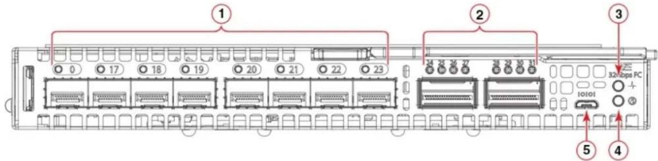
- SFP+ ports 0, 17–23—trunk group 1 2. QSFP ports 24–27 and 28–31—trunk group 2
- Module power and status LED 4. Module identification LED
- External micro-USB console port
NOTE: You can group any two to eight ports within a trunk group to form a trunk. Trunking requires an ISL trunking license.
Passwords
Chassis passwords
If a chassis-created password applies to your IOMs, the instructions included later in this Installation Guide may not function as described.
Chassis passwords follow this hierarchy:
- If you create a password, your password persists and has priority.
- A chassis-created password that is sent to the IOMs is used when:
a. You do not create your own password.
b. The chassis assigns a password that is also pushed to the switch.
- A default password is used when:
a. You do not create your own password.
b. Chassis did not assign a chassis password.
Installation preparation
Topics:
•Multiple switch module installation
• System reliability guidelines
•Static-sensitive devices
•Electrical considerations
•Environmental considerations
- Unpack
- Switch module information
Multiple switch module installation
The Dell EMC PowerEdge MX7000 chassis supports up to two MXG610s switch modules in fabric C slot locations—C1 and C2. During configuration, you must assign the first switch module that you install a unique Ethernet IP address. By default, the switch modules use dynamic host configuration protocol (DHCP) for IP address assignment.
If you do not have a DHCP server, install and configure one switch module at a time to ensure that IP address conflicts do not occur.
System reliability guidelines
To ensure proper cooling, performance, and system reliability, meet the following requirements:
● Each of the Fabric C switch module bays at the back of the MX7000 chassis contains either a switch or a filler blade.
- Replace a removed hot-swappable switch module with an identical switch module or filler blade within 60 seconds of removal.
- Do not block the ventilation areas on the front and back of the MX7000 chassis, power modules, and fans.
- Follow the reliability guidelines detailed in the PowerEdge MX7000 documentation.
Static-sensitive devices

CAUTION: Static electricity can damage the chassis and other electronic devices. To avoid damage, keep static-sensitive devices in their static-protective packages until you are ready to install them.
To reduce the possibility of electrostatic discharge, follow these precautions:
- Limit your movement. Movement can cause static electricity to build up around you.
- Handle the module carefully, hold it by its edges or frame.
- Do not touch solder joints, pins, or exposed printed circuitry.
-
Do not leave the modules where others can handle and damage it.
-
While the module is still in its static-protective package, touch it to an unpainted metal surface on the chassis or any grounded rack component for at least two seconds. This action drains static electricity from the package and from your body.
- Remove the module from its package. Install it directly into the chassis without setting the module down. If you must set down the module, put it back into its static-protective package. Do not place the module on the chassis or on a metal surface.
● Take care when you handle modules during cold weather. Heating reduces indoor humidity and increases static electricity.
- The chassis comes with an electrostatic discharge (ESD) connector. To use the ESD connector, see the documentation included with the chassis.
Electrical considerations
The MXG610s requires a maximum of 140 watts; the MX7000 chassis supplies 12 V power. Out of this 12 V power input, the standby power supply supplies 3.3 V. No other power requirement or provision exists.

CAUTION: Do not attempt to replace the real-time clock (RTC) battery. There is danger of explosion if the battery is incorrectly replaced or disposed off. If the real-time clock begins to lose time, contact your switch module supplier.
Environmental considerations
Ensure proper cooling and ventilation. Verify the following:
●Air vents on the MX7000 are not blocked or restricted.
- Ambient air temperature at the front of the MX7000 does not exceed 40^ (104°F) while the switch module is operating.
Unpack
If you purchased the switch separately from the MX7000 chassis, the shipping carton includes one switch module with two, four, or eight SWL 32-Gbps SFP+ transceivers pre-installed.
- Open the shipping box and inspect the contents for damage.

NOTE: Do not insert a damaged switch module in the blade server chassis. If the switch module is damaged, contact your sales representative before proceeding.
- Remove the foam layer that sits on top of the switch module.
- Remove the switch module from the protective foam surround.
- Remove the foam ends from the switch module.
- Remove the orange protective cover from the internal connectors.
- Slide the switch module out of the antistatic sleeve.

NOTE: Always follow standard ESD precautions.
Switch module information
Before installing the switch module, obtain the switch module serial number. To locate the serial number:
- Locate the serial number on the label attached to the top of the switch module. This label is not visible when you install the switch module in the chassis.
- If you have installed the switch module, enter the chassisShow command. The switch module serial number displays along with other data.
Switch module installation overview
Topics:
•MX7000 chassis preparation
- Switch module installation
- Switch module replacement
MX7000 chassis preparation
Before you insert the switch module in the MX7000 chassis, meet the following conditions:
●The chassis is powered up and meets all its specific power requirements.
●The I/O module bay C1 or C2 is empty and ready to receive the switch module.
- If you are replacing an existing switch module, to maintain the proper cooling level in the chassis, insert the replacement switch module within one minute.
Switch module installation
Insert the switch modules in the MX7000 chassis slots and check that the modules are functioning properly.

NOTE: The switch module works in slots C1 and C2. Do not insert the switch module in any other slot because this action may damage the chassis or switch module connector pins.
- Remove the orange plastic protective cover for the backplane connector.
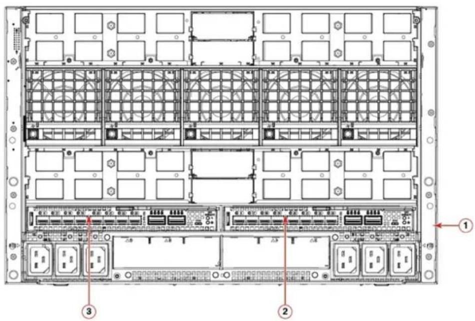
- PowerEdge MX7000 chassis back view.
- Switch module slot C2
-
Switch module slot C1
-
Orient the switch module port side facing you.
The module latch is on the right side.
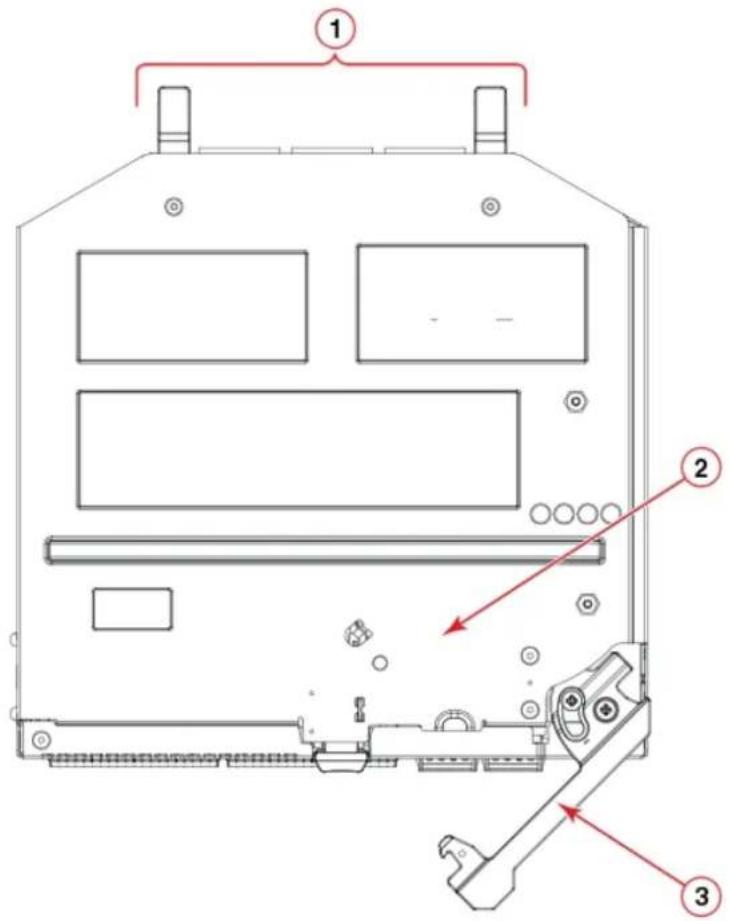
- Backplane connectors
- Switch module top view.
-
Switch module latch in the open position.
-
Open the release lever, and slide the switch module into the slot completely.
You hear a click when the switch module is locked into the I/O module bay. If power is applied to the MX7000, locking the switch module in the module bay powers on the switch.
When you apply power, the switch module runs POSTs which may take up to two minutes to complete. After the power/status LED light is steady green for at least two minutes, the module is ready to use.
- Start from port 0, then port 17, and then the rest of the ports when cabling the SFP+ ports.
You are now ready to insert more SFP+/QSFP optical transceivers, if needed. Be sure to use only Brocade-branded SFP+/QSFP optical transceivers. The MXG610s does not recognize non-Broadcom products.
Switch module replacement
If there is a switch module failure, you must remove and replace the switch module.

NOTE: Before beginning this procedure, you must have a replacement switch module or filler blade available. Never leave the slot on the blade server chassis open for an extended time period. To maintain proper airflow, fill the slot with either a replacement switch module or filler blank.
For more information about removing and replacing the switch module, see the PowerEdge MX7000 Users Guide.
- Back up the switch module configuration to an FTP server using the configUpload command.
The configUpload command uploads the switch module configuration to the server and makes it available for downloading to the replacement switch module if necessary. To ensure that a complete configuration is available for downloading to a replacement switch module, back up the configuration regularly.
- Stop all activity requiring the ports the switch module uses.
To verify that there is no activity, view the switch module LEDs.
- Disconnect all cables from the SFP+/QSFP optical transceivers.
- Remove the SFP+ or QSFP optical transceivers from the switch module external ports.
- Press the release latch, and gently pull the release lever out from the switch module.
You can feel the switch module unseat and move out of the I/O module bay approximately 0.6 cm (0.25 in).
The following shows the open and unlocked view of the release lever and release latch:
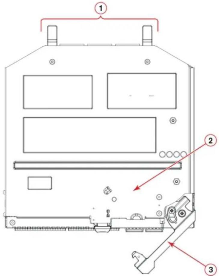
a. Backplane connectors
b. Switch module top view
c. Switch module release lever and latch
- Slide the switch module out of the I/O module bay and set it aside.

NOTE: If you do not insert a replacement switch module, to maintain proper airflow and cooling, use a filler blank to fill the empty slot. Do not leave the slot empty.
- Insert the replacement switch module in the I/O module bay of the blade server chassis.
Complete this step within 60 seconds. - Insert the SFP+ or QSFP optical transceivers.
- Reconnect the cables.
For more information, see the SFP+ or QSFP optical transceivers documentation.
Transceiver and cable installation
Topics:
• Time and items required
• Transceiver and cable safety considerations
- Clean the fiber optic connector
•Optical transceivers
•Fiber optic cables
• Optical transceivers and cabling installation
• Optical transceiver removal and replacement
•Optical transceiver operation
Time and items required
The installation or replacement procedure for one transceiver takes less than five minutes. Ensure that the following items are available:
● Supported Brocade-branded transceivers
- Compatible fiber-optic cables
For current information about supported transceivers, see the Brocade Fibre Channel Transceiver Platform Support Matrix and Brocade Transceiver Module Resources on www.brocade.com.

WARNING: Use only optical transceivers that are qualified by Brocade Communications Systems, Inc. and comply with the FDA Class 1 radiation performance requirements defined in 21 CFR Subchapter I, and with IEC 60825 and EN60825. Optical products that do not comply with these standards might emit light that is hazardous to the eyes.
Transceiver and cable safety considerations
To avoid power leakage and equipment safety, install the transceivers and cables with care.

WARNING: Use only optical transceivers that are Brocade Communications Systems, Inc., qualified and comply with the FDA Class 1 radiation performance requirements defined in 21 CFR Subchapter I, and with IEC 825-2. Optical products that do not comply with these standards might emit light that is hazardous to the eyes.
Clean the fiber optic connector
To ensure the connectors function properly, clean and protect them from dust.
To avoid problems with the connection between the SFP+ or QSFP optical transceivers and the fiber cable connectors, Dell EMC strongly recommends cleaning both connectors each time you disconnect and reconnect them. In particular, dust can accumulate in the connectors and cause problems such as reducing the optic launch power.
To clean the fiber optic cable connectors, Dell EMC recommends using a fiber optic reel-type cleaner.
Optical transceivers
To avoid damage to the optical transceivers, handle them carefully.
Before installing an optical transceiver:
- The housing on the optical transceiver includes an integral guide key that prevents you from inserting the transceiver incorrectly.
- Use minimal pressure when you insert an optical transceiver in the port. Forcing the transceiver into the port can damage the transceiver or the switch module port.
- You can insert or remove an optical transceiver while the blade server chassis is powered on.
- First insert the optical transceiver in the port before connecting the cables.
- Remove the cable from the optical transceiver before you remove the optical transceiver from the switch module.
To order Brocade-branded optical transceivers and cables, contact your sales representative.
For a complete list of optical transceivers and other interoperable hardware, see the Brocade website.
Fiber optic cables
After modifying the switch module IP address and domain name, cable all the external ports to the fabric connections before bringing the switch module online.
To avoid damage to the fiber-optic cables:
- Do not route the cable along a folding cable-management arm.
- When you attach the cable to a device on the slide rails, leave enough slack in the cable. The cable cannot bend to a radius of less than 5.08 cm (2 in.) when the device is extended or becomes pinched when the device retracts.
- Route the cable away from places where it may get snagged by other devices in the rack.
- Do not overtighten the cable straps, or bend the cables to a radius of less than 5.08 cm (2 in.).
- Dell EMC does not recommend tie wraps (also known as zip ties) for optical cables because you can easily overtighten them.
- Do not put excess weight on the cable at the connection point. Ensure that the cable is well supported.
NOTE: Do not bend a cable to a radius of less than 5.08 cm (2 inches) under full tensile load and 3.048 cm (1.2 inches) with no tensile load.
Optical transceivers and cabling installation
NOTE: When cabling SFP+ optical transceivers, start with port 0, then port 17, and then the other ports.
To insert the optical transceivers and the cable connections:
- Insert the optical transceiver in an external port on the switch module until it is firmly seated and the latching mechanism clicks.
Transceivers are keyed to ensure correct orientation. If a transceiver does not install easily, ensure that it is correctly oriented. - Insert the fiber optic cable in the SFP+ or QSFP optical transceiver until the latching mechanism clicks.
Cable connectors are keyed to ensure correct orientation. If a cable connector does not install easily, ensure that it is correctly oriented.
For instructions specific to a cable type, see the cable manufacturer's documentation.
Optical transceiver removal and replacement
- Disconnect the cable from the SFP+/QSFP optical transceiver.

NOTE: Your SFP+/QSFP optical transceivers may differ slightly from the optical transceiver shown in the following illustration, but the steps for removal are the same:
- Remove the SFP+/QSFP optical transceiver according to the manufacturer's instructions.
- Insert the replacement SFP+/QSFP optical transceiver in the appropriate external port of the switch module.
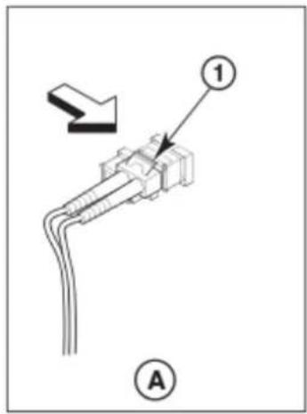
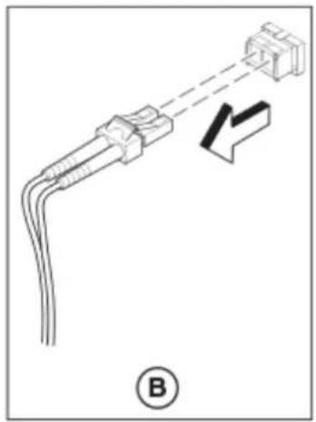
natural_image
Diagram of a connector with wires and a terminal block, no text or symbols present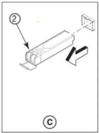
Optical transceiver operation
To verify the transceivers are working correctly, use the following commands:
• sfpShow
- switchShow
- errDump
- fabricShow
For a list of output examples and descriptions, see Brocade Fabric OS Command Reference.
Switch module monitoring
Topics:
- Port-side LEDs
POST results - BOOT results
•Diagnostic tests - Remove a license
- Software upgrade or downgrade
Port-side LEDs
Each switch module uses bicolored external LEDs to indicate operation status.
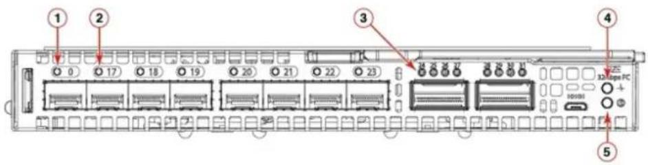
- FC port 0 status LED 2. FC port 17 status LED
- FC port 24 status LED 4. Module power status LED
- Module identification LED
Table 4. Port-side LEDs
| LED Description | |
| Module power and status LED | ●Solid green—The switch is working correctly.●Blinking amber—The switch is working incorrectly. The temperature may be too high, a software error has occurred, or another error is discovered.●Off—There is no power supplied to the FC switch module. Reseat the module and ensure that the chassis power is on and it has adequate power for the I/O module. |
| Module identification LED | ●Off—Module is not identified.●Blinking blue—Module is being identified. |
| FC port status LED | ●Both off—No light or signal carrier—no module, no cable —for the media interface●Solid amber—Receiving light or signal carrier, but not yet online●Slow flashing amber, 2-second intervals—Disabled; results of diagnostics or the portdisable command.●Fast flashing amber, 1/2-second intervals—Error occurred, fault with port.●Solid green—Online; connected with external device over cable●Slow flashing green, 2-second intervals—Online but segmented; Loopback cable or incompatible switch.●Fast flashing green, 1/2-second intervals—Internal loopback, diagnostic.●Flickering green—Online and frames flowing through the port. |
POST results
The power-on self-test (POST) system check performs each time you start up, reboot, or reset the switch module. During the POST, the LEDs activate in various indicator patterns.

NOTE: The default POST diagnostic level is 0; therefore, no POST runs by default. To run the POST, set the POST diagnostic level to a nonzero value before powering on the switch module.
To determine whether POST completed successfully or whether any errors were detected:
- Verify that the LEDs on the switch module indicate a healthy switch.
If one or more LEDs do not display a healthy state, verify that the LEDs are not set to beacon. To verify the LED state, use the switchShow command or web Tools.
- To verify that the switch module is working correctly, use the blade server management application.
- Review the system log for errors.
Any errors detected during POST are written to the system log. This log is accessible through the errShow command.
BOOT results
BOOT includes the following tasks after POST completes:
●Performs universal port configuration
- Initializes links
- Analyzes the fabric. If any ports are connected to other switches, the switch participates in a fabric configuration.
- Obtains a domain ID and assigns port addresses.
- Constructs unicast routing tables.
- Enables normal port operation.
Diagnostic tests
In addition to the POST, the fabric OS includes diagnostic tests to help troubleshoot the hardware and firmware. These tests include internal connections and circuitry, fixed media, and the transceivers and cables in use.
Initiate diagnostic tests with the command line using a secure shell (SSH) session or a terminal set up with a serial connection to the switch. Some tests require the ports to connect by external cables to allow diagnostics to verify the serializer/deserializer interface, transceivers, and cables. For information about the available diagnostic tests, use the diagHelp command.
All diagnostic tests are run at 32 Gbps link speeds.

NOTE: Diagnostic tests can temporarily lock the transmit and receive link speed.
- Off—No light or signal carrier; no module or cable for the media interface.
●Solid amber—Receiving light or signal carrier, but not yet online, - Slow flashing amber, 2-second intervals—Disabled; the result of diagnostics or the portDisable command.
- Fast flashing amber, 1/2-second intervals—Error; a fault with a port.
Remove a license
When you remove licenses, some features require that you reboot the switch. Some features require you to disable and reenable selected ports or the entire switch. For example, Dynamic POD license requires you to disable and reenable the chassis or the appropriate ports.
- Enter the license --show command to display the active licenses.
- Issue the license --remove -key
The license key is case-sensitive, and you must enter it exactly as shown. If the license key includes spaces, enclose the entire string in double quotation marks.
- Take the appropriate action that the command output indicates.
Depending on the license type, you may be prompted to reboot the switch or to enable the ports.
- Enter the license --show command to verify that the license is removed.
If there are no license keys, the command output displays No licenses.
Software upgrade or downgrade
To upgrade the firmware, perform the following steps:
- Enter the version command to verify the current firmware version.
- Back up your switch configuration before the firmware download.
- (Optional) For extra support, connect the switch to a computer with a serial console cable.
Log and include all serial consoles and any open network connection sessions, such as SSH, with any troubleshoot reports.
- Enter the supportSave command to collect all current core files before the firmware download.
This information helps to troubleshoot the firmware download process if there is a problem.
- Enter the version command to determine the fabric OS version and other build information.
Firmware upgrades are available for customers with support service contracts and for partners on the Dell EMC website at www.dell.com/support.
- Decompress the firmware package.
Use the UNIX tar command for .tar files, the gunzip command for all .gz files, or a Windows unzip program for all .zip files.
When you unpack the downloaded firmware, it expands into a directory that is named according to the firmware version.
The firmwareDownload command, when issued with the path to the directory where the firmware is stored, performs an automatic search for the correct package file type associated with the switch.
- Enter the firmwareDownload command.
NOTE: When upgrading multiple switch modules, complete the following steps on each switch module before you upgrade the next one.
NOTE: Do not interrupt the firmware download process. If you encounter a problem, wait for the 30 minutes time-out before issuing the firmware download command again. Disrupting the process; for example, by disconnecting the switch from the power source, can render the switch inoperable and may require you to seek help from your switch service provider.
- Start a separate CLI session on the switch module while the upgrade is proceeding.
To monitor the upgrade progress, use the firmwareDownloadStatus command.
- Enter the version command after the switch module reboots to verify the firmware upgrade.
Initial setup and verification
Before you begin the switch module configuration, ensure that you configure the MX7000 chassis correctly. For more information, see the OpenManage Enterprise Module Edition User Guide.
To configure and connect to the switch module, you need the following:
●MXG610s switch module installed in a MX7000
●A workstation with access to the OME-M GUI
●A serial cable to connect to the switch module serial console port, if required
NOTE: You can change the switch module IP address only through the OME-M GUI.
- An unused IP address and a corresponding subnet mask and gateway address if you did not use DHCP to set the DHCP address
- Access to an FTP server to back up the switch module configuration
Topics:
- Switch module power
- IP addresses
•Static IP addresses - Serial connection
- Set date and time
- Chassis and switch name
- Set domain ID
- Software licenses
- Verify device operation
- Configuration backup
Switch module power
The MX7000 chassis power supply provides power to the switch module. There is no separate power supply required.
IP addresses
DHCP
DHCP is the default IP address mode. When using DHCP, the switch obtains its IP address, subnet mask, and default gateway address from the DHCP server. The DHCP client can only connect to a DHCP server that is on the same subnet as the switch. If your DHCP server is not on the same subnet as the switch, use a static IP address.
Static IP addresses
Dell EMC recommends configuring the switch module through the Dell EMC OpenManage Enterprise — Modular (OME-M) graphical user interface (GUI). Use this management GUI to configure the switch IP address, host name, and password. By default, the IP address mode is set to DHCP. Use the GUI to assign a static IP address. To configure the FC switch module, follow these steps:
- Log in to the OME-M GUI.

OpenManage Enterprise Modular

Home

Devices

Configuration

Alerts

Monitor

Application Settings
2. Select Devices > I/O modules.
The I/O modules display.

NOTE: You may also access the WebTools configuration UI to manage the switch module by typing the switch module IP address into any supported web browser.
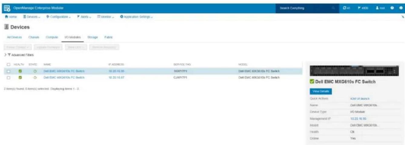
- Select the I/O module name, IP address, or View Details on the right side of the display.
The Overview tab is displayed. Select the Settings tab.

OpenManage Enterprise Modular

Home

Devices

Configuration

Alerts

Monitor √

Application Settings
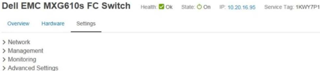
- Click and expand the Network option. Select the required check boxes, and complete the IPv4 or IPv6 settings, DNS server settings, and optionally the management VLAN ID. Click Apply.
√ Network
IPv4 Settings
| Enable IPv4 | ☑ |
| Enable DHCP | ☑ |
| IP Address | 10.20.16.143 |
| Subnet Mask | 255.255.240.0 |
| Gateway | 10.20.16.1 |
IPv6 Settings
| Enable IPv6 | ☑ |
| Enable Autoconfiguration | ☑ |
| IPv6 Address | 2620:100:0:fa05::f87a |
| Prefix Length | 64 |
| Gateway | fe80::21b:edff:fe0b:2400 |
DNS Server Settings
| Preferred DNS Server | 10.31.2.10 | |
| Alternate DNS Server 1 | 10.31.2.1 | × |
| Alternate DNS Server 2 |
Management VLAN
| Enable VLAN | □ |
| VLAN ID |
Apply
Discard
- Click and expand the Management option. Specify a hostname and root password. Click Apply.
▼ Management
Host Name
Root Password
MXG610s
■■■■
Apply
Discard
- Click and expand the Monitoring option. Select the Enable SNMP check box, the SNMP version, and enter a read community string. Click Apply.
√ Monitoring
Enable SNMP
SNMP Version
Read Community String

○ SNMP v1
SNMP v2
public|common|FibreChannel
Apply
Discard
- Click and expand the Advanced Settings option. Select the needed check boxes.
√ Advanced Settings
Replicate Time Configuration from Chassis

Replicate Alert Destination Configuration from Chassis

Apply
Discard
- Click Apply.
You have configured the IP address and other settings for the switch module.
Serial connection
To log in to the switch module through the serial connection on the front panel, perform the following steps:
- Connect the console cable with the micro-USB connector to the console port on the switch module and to a USB port on the workstation.
- Disable any serial communication programs running on the workstation such as synchronization programs.
- Open a terminal emulator application such as PuTTY, XShell, or SecureCRT on a Windows PC, or TERM, TIP, or C-Kermit in a LINUX environment. Configure the application as follows:
- In a Windows environment, use the following values:
- Bits per second—9600
○Databits—8
oParity—None
○Stop bits—1
○Flow control—None; must be disabled on the host side

NOTE: Flow control is not supported on the serial connection when attached to a remote terminal. You must disable flow control on the customer-side remote terminal server in addition to the host-side clients.
- In a UNIX environment using TIP, enter tip /dev/ttyb -9600. at the prompt.
-
If you are already using ttyb, use ttya instead and enter tip /dev/ttya -9600 at the prompt.
-
Press enter when the terminal emulator application stops reporting information to display the login prompt.
Switch Console Login:
- Log in to the switch module as admin, using the default password: password.
You are prompted to change the default admin and user passwords at initial login. Write down the new passwords, and keep this information in a secure location.
Fabric OS (swDir)
swDir login: admin
Password:
Please change your passwords now.
Use Control-C to exit or press 'Enter' key to proceed.
swDir:admin>
- (Optional) Modify passwords.
To skip modifying the password, press Ctrl+C.

NOTE: Passwords are 8 to 40 characters long. They must begin with an alphabetic character. They can include numeric characters, the period (.), and the underscore (_) only. Passwords are case-sensitive, and do display when you enter them on the command line.
Set date and time
Use date and time settings for logging events, error detection, and troubleshooting. However, device operation does not depend on the date and time; a device with incorrect date or time values still functions properly.
You can synchronize the local time of the principal or primary fabric configuration server (FCS) device to that of an external Network Time Protocol (NTP) server.
- Log in to the device as admin.
- Enter the date ["newdate"] command at the command line.
The "newdate" variable specifies the new date and time enclosed in double quotation marks. The operand is optional; if omitted, the current date and time displays. Date and time are specified as a string in the mddhhmmyy format:
- mm: Specifies the month. Valid values are 01–12.
- dd: Specifies the date. Valid values are 01–31.
- hh: Specifies the hour. Valid values are 00–23.
- mm: Specifies the minutes. Valid values are 00–59.
- yy: Specifies the year. Valid values are 00–37 and 70–99. Year values from 70 to 99 are interpreted as 1970-1999; year values from 00 to 37 are interpreted as 2000-2037.
device:admin> date
Thu Dec 22 14:05:10 UTC 2016
device:admin> date "1222140616"
Thu Dec 22 14:06:00 UTC 2016
Set time zone
The default time zone is Coordinated Universal Time (UTC). You can only set the time zone once because the value is stored in nonvolatile memory.
- Log in as admin.
-
Enter the tsTimeZone --interactive command and follow the prompts, or enter the tsTimeZone - {houroffset, minuteoffset} command as follows:
-
For Pacific Standard Time, enter tsTimeZone -8,0.
- For Central Standard Time, enter tsTimeZone -6,0.
- For Eastern Standard Time, enter tsTimeZone -5,0.
Table 5. tsTimeZone command parameters
| Local time tsTimeZone command parameter—difference from UTC | |
| Atlantic standard -4,0 | |
| Atlantic daylight -3,0 | |
| Eastern standard -5,0 | |
| Eastern daylight -4,0 | |
| Central standard -6,0 | |
| Central daylight -5,0 | |
| Mountain standard -7,0 | |
| Mountain daylight -6,0 | |
| Pacific standard -8,0 | |
| Pacific daylight -7,0 | |
| Alaskan standard -9,0 | |
| Alaskan daylight -8,0 | |
| Hawaiian standard -10,0 | |
Local time synchronization
To synchronize the local time of the principal or primary FCS device with an external NTP server:
- Log in as admin.
- Enter the tsClockServer [ipaddr] command.
The [ipaddr] variable represents the IP address of the NTP server that the device accesses. This argument is optional; by default, the value is LOCL.
switch:admin> tsclockserver xxx.xxx.xxx.xx
Updating Clock Server configuration...done.
Updated with the NTP servers
Chassis and switch name
To identify the device uniquely, it is important to change the chassis and switch names. This name change also helps identify the device for accurate log and error tracking. Specify an easily understandable and meaningful name for the chassis and switch names.
- Log in to the device through SSH using the admin account.
- Change the chassis name using the chassisName command. device:admin> chassisname Chassis_001
- Change the switch name using the switchName command.
device:admin> switchname Switch_001
Committing configuration...
Done
Switch name has been changed. Please re-login to the switch for the change to applied
Set domain ID
To set the switch domain ID:
- Log in to the switch through SSH using the admin account.
- Modify the domain ID if required.
The default domain ID is 1. If the switch is not powered on until after it is connected to the fabric and the default domain ID is already in use, the domain ID for the new switch automatically resets to a unique value. If the switch is connected to the fabric after it is powered on and the default domain ID is already in use, the fabric segments. To find the domain IDs that are currently in use, enter the fabricShow command on another switch in the fabric.
a. Disable the switch by entering the switchDisable command.
b. Enter the configure command.
The command prompts display sequentially; enter a new value or press enter to accept each default value.
c. Enter y after the Fabric param prompt.
Fabric param (yes, y, no, n): [no] y
d. Enter a unique domain ID, such as the domain ID the previous switch used, if available.
Domain: (1..239) [1] 3
e. Complete the remaining prompts or press Ctrl+D to accept the remaining settings without completing all the prompts.
f. Re-enable the switch by entering the switchEnable command.
Software licenses
Enter the license --show command to determine licensing information.
Verify device operation
To verify correct device operation:
-
Check the LEDs to verify that all components are functional.
-
Verify the correct device operation by entering the following commands from the workstation:
- switchShow—displays switch status and information.
- tempShow—displays temperature status and information.
●historyShow—displays device history.
- errDump—displays any errors.
The switchShow command provides the following information:
switch1:admin> switchshow
switchName: switch1
switchType: 175.0
switchState: Online
switchMode: Native
switchRole: Subordinate
switchDomain: 70
switchId: fffc46
switchWwn: 10:00:00:05:1e:65:79:04
zoning: ON (PERF_CFG)
switchBeacon: OFF
FC Router: OFF
Fabric Name: abcfabric
Allow XISL Use: OFF
LS Attributes: [FID: 128, Base Switch: No, Default Switch: Yes, Address Mode 0]
Index Port Address Media Speed State Proto

0 0 460000 id N32 Online FC F-Port 20:05:00:11:0d:a8:01:00
1 1 460100 id N32 Online FC F-Port 20:01:00:11:0d:bb:01:00
2 2 460200 id N32 Online FC F-Port 20:03:00:11:0d:84:01:00
3 3 460300 id N32 Online FC F-Port 20:07:00:11:0d:26:01:00
4 4 460400 id N32 Online FC F-Port 10:00:8c:7c:ff:5c:c5:01
5 5 460500 id N32 Online FC F-Port 10:00:8c:7c:ff:58:4c:00
6 6 460600 id N32 Online FC F-Port 10:00:8c:7c:ff:5c:c9:01
7 7 460700 id N32 Online FC F-Port 10:00:8c:7c:ff:5c:bd:00
8 8 460800 -- N32 No_Module FC
9 9 460900 -- N32 No_Module FC
10 10 460a00 -- N32 No_Module FC
11 11 460b00 -- N32 No_Module FC
12 12 460c00 -- N32 No_Module FC
13 13 460d00 -- N32 No_Module FC
14 14 460e00 -- N32 No_Module FC
15 15 460f00 -- N32 No_Module FC
16 16 461000 -- N32 No_Module FC
17 17 461100 -- N32 No_Module FC
18 18 461200 -- N32 No_Module FC
19 19 461300 -- N32 No_Module FC
20 20 461400 -- N32 No_Module FC
21 21 461500 -- N32 No_Module FC
22 22 461600 -- N32 No_Module FC
23 23 461700 -- N32 No_Module FC
<Output truncated>
Configuration backup
Always keep a backup copy of your configuration files. You can use these backup files to restore your configuration when needed. Dell EMC recommends backing up the configuration regularly to ensure that a complete configuration is available for downloading.
The following recommendations apply:
- Keep backup copies of the startup configuration for all switches in the fabric.
- Upload the configuration backup copies to an external host or an attached USB device.
- Avoid copying configuration files from one switch to another. Instead, restore the switch configuration files from the backup copy.
Backup procedure
To back up the switch module configuration to an FTP server:
- Open an SSH session to the serial console.
- Enter the configUpload command.
You are presented with a series of prompts.
- Follow the prompts to upload the configuration.
The configUpload command uploads the switch configuration to the server, making it available for downloading to a replacement switch module, if required.
Technical specifications
This section highlights the features and specifications for the Dell EMC MXG610s 32 Gbps FC switch module.
System specifications
Table 6. System specifications
| System components Description | |
| Enclosure Less than 1U module—2.75 cm / 1.08 inches | |
| Power inlet Internal to the chassis | |
| Power supplies | 12 V power supply from the Dell EMC PowerEdge MX7000 chassis3.3 V standby power supply derived from 12 V source on the switch moduleMaximum power—150 Watts |
| Fans Internal to the chassis | |
| Cooling Integrated system cooling; back-to-front port-side exhaust | |
| System architecture Nonblocking shared memory switch | |
| System processors Freescale PowerPC T1022E with two cores at 1.2 GHz | |
Table 7. Fibre Channel specifications
| System components Description | |
| Fibre Channel ports Default switch mode | ●16 external ports supporting 8 Gbps, 16 Gbps, and 32 Gbps speeds using eight SFPs and two QSFPs●16 internal ports supporting 16 Gbps and 32 Gbps speeds |
| ANSI Fibre Channel protocol Fibre Channel Physical and Signaling Interface standard—FC-PH | |
| Modes of operation Fibre Channel Class 2, Class 3, and Class F | |
| Fabric initialization Complies with FC-SW-5 | |
| FCIP—IP over Fibre Channel Complies with FC-IP 2.3 of FCA profile | |
| Port status Bicolor LED—amber/green |
Table 8. Default switch module settings
| Setting | Description |
| Switch name | Dell EMC MXG610s |
| Default switch mode | Access Gateway mode |
| IP address | Before factory restore defaults: 10.77.77.77After factory restore defaults: 192.168.0.200+(SlotID[1~2]) |
| Setting Description | |
| Subnet mask After factory restore defaults: 255.255.255.0 | |
| Gateway IP address After factory restore defaults: 192.168.0.1 | |
| Username admin | |
| Password admin |
Table 9. Default access gateway mode settings
| Setting Description | |
| N-ports: automatic failover Enabled on all ports | |
| N-ports: automatic failback Enabled on all ports | |
| APC policy default Disabled | |
| Group policy default Enabled | |
| ADS policy default Disabled | |
| Preferred secondary failover None specified |
Table 10. Default access gateway mode port mapping
| Internal port: F_port / Server port External port: N_port / Fabric port HBA Mezzanine Port | ||
| 10 Lane 0 of Server Sled 1 | ||
| 2 | 17 | Lane 0 of Server Sled 2 |
| 3 | 18 | Lane 0 of Server Sled 3 |
| 4 | 19 | Lane 0 of Server Sled 4 |
| 5 20 | Lane 0 of Server Sled 5 | |
| 6 21 | Lane 0 of Server Sled 6 | |
| 7 | 22 | Lane 0 of Server Sled 7 |
| 8 23 | Lane 0 of Server Sled 8 | |
| 9 24 | Lane 1 of Server Sled 1 | |
| 10 | 25 | Lane 1 of Server Sled 2 |
| 11 | 26 | Lane 1 of Server Sled 3 |
| 12 | 27 | Lane 1 of Server Sled 4 |
| 13 | 28 | Lane 1 of Server Sled 5 |
| 14 | 29 | Lane 1 of Server Sled 6 |
| 15 | 30 | Lane 1 of Server Sled 7 |
| 16 | 31 | Lane 1 of Server Sled 8 |
Table 11. Management port
| System components | Description |
| Console port | Micro-USB; external front panel |
| Ethernet port | nternal backplane |
Table 12. LEDs
| System components Description | |
| Module power and status LED One bicolor I/O module power and status LED at the right; upper side. | |
| Module identification LED One blue I/O module identification LED at the right; lower side. | |
| FC port status and fault LEDs | One bicolor port status; green/amber, LED above each SFP+ FC port.Four bicolor port status; green/amber, LED above each QSFP port. |
Table 13. Weight and physical dimension
| Height Width Depth Weight—empty Weight—fully loaded | ||||
| .75 cm | 21.45 cm | 24.10 cm | 1.35 kg | 1.61 kg |
| 1.08 in | 8.44 in | 9.49 in | 2.98 lb | 3.55 lb |
Table 14. Environmental requirements
| Condition Operational Storage | ||
| Ambient temperature -5°C to 50°C (23°F to 122°F) | -40°C to 70°C (-40°F to 158°F) | |
| Relative humidity, noncondensing 5% to 95% | 5% to 95% (Non-condensing) | |
| Altitude, above sea level Up to 3200 m (10,000 feet) | 0 to 12192 m (40,000 feet) | |
| Shock 10.0 G for 11 ms, half-sine wave | Half Sine Shock: 105 G for 2msSquare Wave Shock: 32 G with velocity change of 270 in/sec squaredTrapezoidal wave shock: 70 G for 12ms | |
| Vibration | Random Vibration: 0.4 Grms at 5-500 Hz for 60 minutes/axisSine Vibration: 1G at 5-500-5 Hz for 15 minutes/axis | Random Vibration:1.88 Grms at 10-500 Hz for 15 minutes/axisSine Vibration:2.4 Grms at 5.9-500 Hz for 15 minutes/axis |
| Airflow | Maximum: 10.0 cfm | N/A |
| Heat dissipation | Refer to the Power consumption sections. | N/A |
| Operating noise | N/A N/A |
Table 15. Power consumption per module
| Module name | Power consumption |
| MXG610s FC switch module | 12 V power supply from the Dell EMC PowerEdge MX7000 chassisIdle: 50 Watts @ 25°CMini-Cycle: 57 Watts @ 25°CMaximum: 60 Watts @ 25°C |
Table 16. Fibre Channel data port specifications
| Port numbers Media type Description | ||
| 0, and 17 through 23 8-, 16- or 32-Gbps SFP- | ports Compatible with SWL and LWL | transceivers. Can be F_Port, N_Port, or E_Port |
| 24 through 31 4x16- or 4x32-Gbps QSFP ports | Compatible with SWL and LWL | transceivers. Can be F_Port, N_Port, or E_Port |
Table 17. Fibre Channel data transmission ranges
| Port speed (Gbps) Cable | size (microns) Short wa | velength(SWL) | Long wavelength(LWL) | Extended longwavelength (ELWL) |
| 8 | 50 | 50 m (164 ft) (OM2)150 m (492 ft) (OM3)190 m (623 ft) (OM4) | N/A N/A | |
| 62.5 21 m (69 ft) N/A N/A | ||||
| 9 N/A 10 km (6.2 miles) 25 | km (15.5 miles) | |||
| 16 50 | 35 m (115 ft) (OM2)100 m (328 ft) (OM3)125 m (410 ft) (OM4) | N/A N/A | ||
| 62.5 15 m (49 ft) N/A N/A | ||||
| 9 N/A 10 km (6.2 miles) 25 | km (15.5 miles) | |||
| 32 50 | 70 m (230 ft) (OM3)100 m (328 ft) (OM4) | N/A N/A | ||
| 62.5 N/A N/A N/A | ||||
| 9 N/A 10 km (6.2 miles) 25 | km (15.5 miles) |
Table 18. Serial port, Micro-USB specifications
| Pin | Signal | Description |
| 1 | VCC | +5 VDC |
| 2 | D- | Data - |
| 3 | D+ | Data + |
| 4 | ID | USB OTG ID |
| 5 | GND | Ground |
Table 19. Serial port, protocol specifications
| Parameter | Value |
| Baud | 9600 |
| Data bits | 8 |
| Parity | None |
| Stop bits | 1 |
| Flow control | None |
Table 20. Memory specifications
| Memory Type Size | ||
| Main memory | DDR3L SDRAM with 8-bit ECC,SORDIMM package, operating at 1200 MT/s | 2 GB, 64-bit |
| Boot flash Parallel NOR flash embedded memory 16 MB | ||
| eUSB module 2 GB | ||
Table 21. Support for extended fabrics distances
| SFP and QSFP Minimum distance Maximum distance | ||
| ELWL 10 km; 6.21 miles 3000 km; 1864.11 miles |
EMC regulatory Compliance
•2014/30/EU
●AS/NZS CISPR32 (Australia)(Class A)
CISPR 32
•CNS 13438
●EM 55032 (CE Mark)(Class A)
•EN 300 386
•EN 55024
- EN 61000-3-2
•EN 61000-3-3
●FCC Part 15, Subpart B
- GB 9254
- ICES-003
•KN 32
•KN 35
•TCVN 7189
•VCCI
Safety regulatory compliance
•2014/35/EU
•CNS 14336-1
•EN/UL 60825
●EN/UL/CSA/IEC 60950-1
- GB 49431
Environmental regulatory compliance
- 1907/2006 of the European Parliament and of the Council of 18 December 2006 concerning the Registration, Evaluation, Authorisation and Restriction of Chemicals (EU REACH).
• 2006/66/EC - batteries and accumulators and waste batteries and accumulators (EU battery directive). - 2011/65/EU - Restriction of the use of certain hazardous substance in electrical and electronic equipment (EU RoHS).
●2012/19/EU - Waste electrical and electronic equipment (EU WEEE).
●30/2011/TT-BCT - Vietnam circular.
●94/62/EC - packaging and packaging waste (EU).
• Section 1502 of the Dodd-Frank Wall Street Reform and Consumer Protection Act of 2010 - U.S. Conflict Minerals. - SJ/T 11363-2006 Requirements for Concentration Limits for Certain Hazardous Substances in EIPs (China).
- SJ/T 11364-2006 Marking for the Control of Pollution Caused by EIPs (China).
Regulatory statements
Topics:
•Taiwan BSMI statement
• Canadian requirements
- CE statement
•China CCC statement
•China ROHS
•Europe and Australia CISPR 32 Class A Warning
•US only FCC warning
•Germany statement
•Republic of Korea KCC statement
Taiwan BSMI statement
警告使用者:
WARNING: This product is Class A. In a domestic environment, this product may cause radio interference. You may be required to take adequate measures.
Canadian requirements
This Class A digital apparatus meets all requirements of the Canadian Interference-Causing Equipment Regulations, ICES-003 Class A.
NOTE: This product is a Class A. In a domestic environment, this product might cause radio interference. You might be required to take corrective measures.
The standards compliance label on this device contains the CE mark that indicates this system conforms to the provisions of the following European Council directives, laws, and standards:
●Electromagnetic Compatibility (EMC) Directive 2014/30/EU
●Low Voltage Directive (LVD) 2014/35/EU
- EN 55032/EN 55024 (European Immunity Requirements)
- EN61000-3-2/JEIDA (European and Japanese Harmonics Spec)
- EN61000-3-3
China CCC statement

China-CCC Warning statements
在维修的时候一定要断开所有电源 (English translation"disconnect all power sources before service")

For non tropical use:
Warning for Class A:
声明
English translation of above statement
This is a Class A product. In a domestic environment this product may cause radio interference, in which case the user may be required to take adequate measures.
China ROHS
Refer to the latest revision of the China ROHS document, P/N 53-1000428-xx, that ships with the product.
Europe and Australia CISPR 32 Class A Warning
This product is a Class A. In a domestic environment this product may cause radio interference. You may be required to take adequate measures.
US only FCC warning
This equipment has been tested and complies with the limits for a Class A computing device pursuant to Part 15 of the FCC Rules. These limits provide reasonable protection against harmful interference when the equipment is operated in a commercial environment.
This equipment generates, uses, and can radiate radio frequency energy, and if not installed and used in accordance with the instruction manual, might cause harmful interference to radio communications. Operation of this equipment in a residential area is likely to cause harmful interference, in which case you are required to correct the interference at the user's own expense.
Germany statement
Machine noise information regulation—3. GPSGV, the highest sound pressure level value is 48.5 dB(A) in accordance with EN ISO 7779.
Republic of Korea KCC statement
Class A device, Broadcasting Communication Device for Office Use: This device obtained EMC registration for office use, Class A, and may be used in places other than home. Sellers and/or users need to take note of this.
Caution and danger notices
Topics:
• Cautions
- Danger notices
Cautions
A Caution statement alerts you to situations that can be potentially hazardous to you or cause damage to hardware, firmware, software, or data.
NOTE: Static electricity can damage the chassis and other electronic devices. To avoid damage, keep static-sensitive devices in their static-protective packages until you are ready to install them.
A Danger statement indicates conditions or situations that can be potentially lethal or extremely hazardous to you. Safety labels are also attached directly to products to warn of these conditions or situations.
NOTE: Use only optical transceivers that are qualified by Brocade Communications Systems, Inc. and comply with the FDA Class1 radiation performance requirements defined in 21 CFR Subchapter I, and with IEC 60825 and EN60825. Opticalproducts that do not comply with these standards might emit light that is hazardous to the eyes.
The Dell EMC support site provides documents and tools to help you use Dell EMC equipment and mitigate network outages. Through the support site you can obtain technical information, access software upgrades and patches, download available management software, and manage your open cases. The Dell EMC support site provides integrated, secure access to these services.
To access the Dell EMC support site, go to www.dell.com/support/. To display information in your language, scroll down to the bottom of the web page and select your country from the drop-down menu.
- To obtain product-specific information, enter the 7-character Service Tag or 11-digit express service code of your switch, which is found on the pull-out tag, also known as a luggage tag, and click Submit.
- To receive more technical support, click Contact Us. On the Contact Information web page, click Technical Support.
To access switch documentation, go to www.dell.com/manuals/ and enter your switch type.
To search for drivers and downloads, go to the Drivers & Downloads tab for your switch.
To participate in Dell EMC community blogs and forums, go to www.dell.com/community.
- MXG610s Fibre Channel Switch Module Installation Guide
- Contents
- Chapter 1: About this guide....5
- Chapter 2: Switch module overview....8
- Chapter 3: Installation preparation....11
- Chapter 4: Switch module installation overview....13
- Chapter 5: Transceiver and cable installation....16
- Chapter 6: Switch module monitoring....19
- Chapter 7: Initial setup and verification....22
- Chapter 8: Technical specifications....30
- Chapter 9: Regulatory statements....36
- Chapter 10: Caution and danger notices.... 39
- Chapter 11: Dell EMC support....41
- About this guide
- Topics:
- Supported hardware and software
- Document conventions
- Text formatting conventions
- Command syntax conventions
- Switch module overview
- Hardware features
- Supported licenses
- Module management options
- Face-plate view
- Passwords
- Chassis passwords
- Installation preparation
- Multiple switch module installation
- System reliability guidelines
- Static-sensitive devices
- Electrical considerations
- Environmental considerations
- Unpack
- Switch module information
- Switch module installation overview
- MX7000 chassis preparation
- Switch module installation
- Switch module replacement
- Transceiver and cable installation
- Time and items required
- Transceiver and cable safety considerations
- Clean the fiber optic connector
- Optical transceivers
- Fiber optic cables
- Optical transceivers and cabling installation
- Optical transceiver removal and replacement
- Optical transceiver operation
- Switch module monitoring
- Port-side LEDs
- POST results
- BOOT results
- Diagnostic tests
- Remove a license
- Software upgrade or downgrade
- Initial setup and verification
- Switch module power
- IP addresses
- DHCP
- Static IP addresses
- OpenManage Enterprise Modular
- Select Devices > I/O modules.
- Serial connection
- Set date and time
- Set time zone
- Local time synchronization
- Chassis and switch name
- Set domain ID
- Software licenses
- Verify device operation
- Configuration backup
- Backup procedure
- Technical specifications
- System specifications
- EMC regulatory Compliance
- Safety regulatory compliance
- Environmental regulatory compliance
- Regulatory statements
- Taiwan BSMI statement
- Canadian requirements
- China CCC statement
- 声明
- China ROHS
- Europe and Australia CISPR 32 Class A Warning
- US only FCC warning
- Germany statement
- Republic of Korea KCC statement
- Caution and danger notices
- Cautions
Brand : DELL
Model : MXG610s
Category : Switch