BT 2010 - Battery charger GYS - Free user manual and instructions
Find the device manual for free BT 2010 GYS in PDF.
User questions about BT 2010 GYS
0 question about this device. Answer the ones you know or ask your own.
Ask a new question about this device
Download the instructions for your Battery charger in PDF format for free! Find your manual BT 2010 - GYS and take your electronic device back in hand. On this page are published all the documents necessary for the use of your device. BT 2010 by GYS.
USER MANUAL BT 2010 GYS
text_image
DHC 100% 100% 100% 100% 100% 100% 100% 100% 100% 100% 100% 100% 100% 100% 100% 100% 100% 100% 100% 100% 100% 100% 100% 100% 85% 85% 85% 85% 85% 85% 85% 85% 85% 85% 85% 85% 85% 85% 85% 85% 85% 85% 85% 85% 85% 85% 85% 85% 85% 85% 85% 85% 85% 85% 75% 75% 75% 75% 75% 75% 75% 75% 75% 75% 75% 75% 75% 75% 75% 75% 75% 75% 75% 75% 75% 75% 75% 75% 75% 75% 75% 75% 75% 75 75% 75 75% 75 75% 75 75% 75 75% 75 75% 75 75% 75 75% 75 75% 75 75% 75 75% 75 75% 75 75% 75 75% 75 70% 70% 70% 70% 70% 70% 70% 70% 70% 70% 70% 70% 70% 70% 70% 70% 70% 70% 70% 70% 65% 65% 65% 65% 65% 65% 65% 65% 65% 65% 65% 65% 65% 65% 65% 65% 60% 60% 60% 60% 60% 60% 60% 60% 60% 60% 60% 60% 60% 60% 60% 60% 60% 60% 60% 60% 60% 60% 60% 60% 60% 60% 60% 60% 60% 60% 45% 45% 45% 45% 45% 45% 45% 45% 45% 45% 45% 45% 45% 45% 45% 45% 45% 45% 45% 45% 45% 45% 40% 40% 40% 40% 40% 40% 40% 40% 40% 40% 40% 40% 40% 40% 40% 40% 40% 40% 40% 40% 40% 40% 40% 40% 40% 40% 40% 40% 40% 40% 35% 35% 35% 35% 35% 35% 35% 35% 35% 35% 35% 35% 35% 35% 35% 35% 35% 35% 35% 35% 35% 35% 30% 30% 30% 30% 30% 30% 30% 30% 30% 30% 30% 30% 30% 30% 30% 30% 30% 30% 30% 30% 30% 30% 30% 30 2.9999999999999999999999999999999999999999999999999999999999999999999999999999999999999999999999999999 8.222222222222222222222222222222222222222222222222222222222222222222222222222222222222222222222222FR 2-6
EN 7-11
DE 12-16
ES 17-21
RU 22-26
NL 27-31
IT 32-36
BT 2010
Testeur de batterie
Battery tester
Batterietester
Probador de batería
Тестер батарей
Batterijtester
Tester di batteria
INSTRUCTIONS DE SÉCURITÉ

text_image
Collection of logos and symbols including CE, ERC, UK, CA, and a crossed-out symbolnatural_image
Close-up of a green plastic clip being inserted into a black electronic device (no visible text or symbols)natural_image
Close-up of a black electronic device with a green circuit board and a white cylindrical component (no visible text or symbols)natural_image
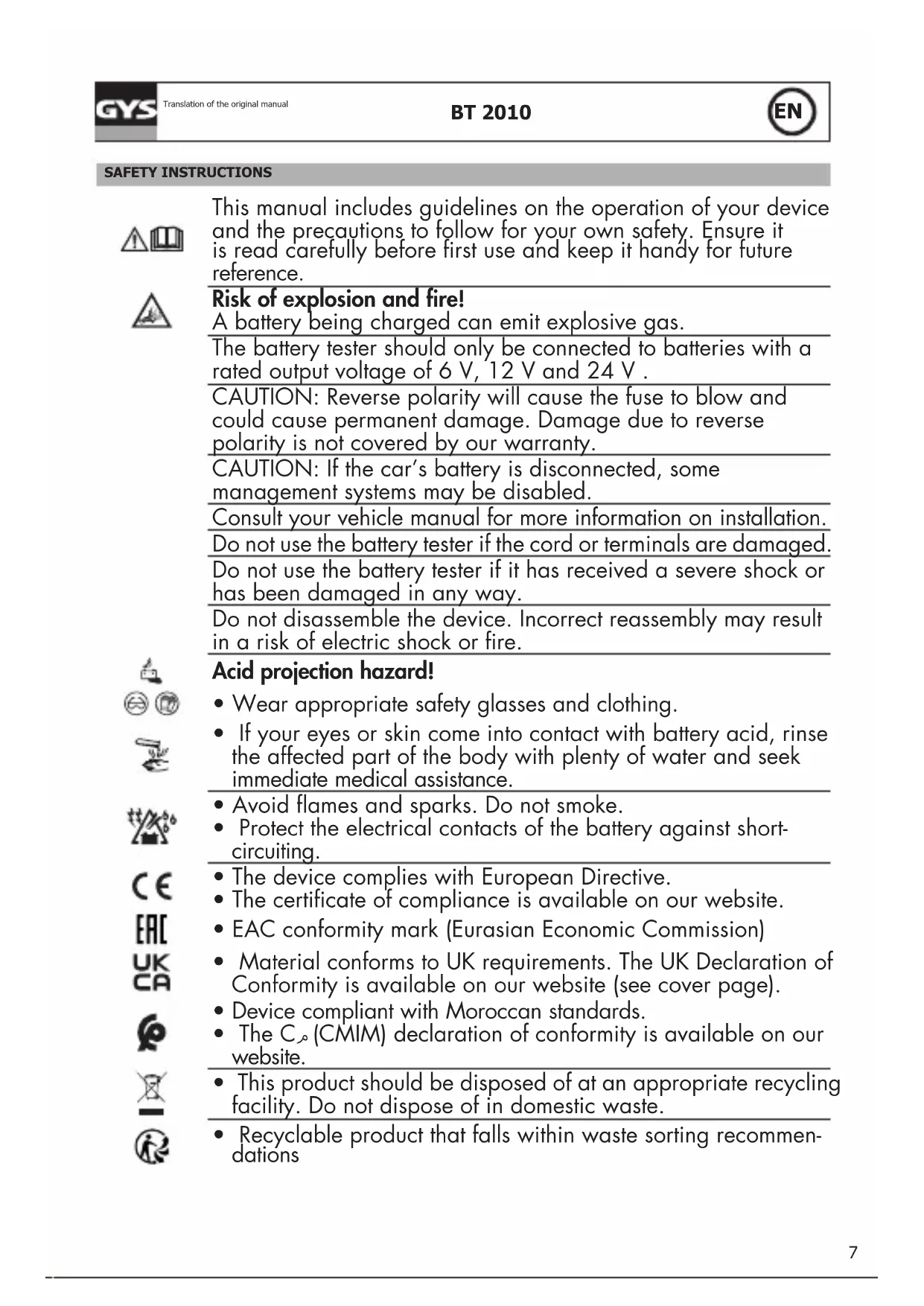
Close-up of a black electronic device with green screen and white label (no readable text or symbols)This manual includes guidelines on the operation of your device and the precautions to follow for your own safety. Ensure it is read carefully before first use and keep it handy for future reference.
Risk of explosion and fire!
A battery being charged can emit explosive gas.
The battery tester should only be connected to batteries with a rated output voltage of 6 V, 12 V and 24 V.
CAUTION: Reverse polarity will cause the fuse to blow and could cause permanent damage. Damage due to reverse polarity is not covered by our warranty.
CAUTION: If the car's battery is disconnected, some management systems may be disabled.
Consult your vehicle manual for more information on installation.
Do not use the battery tester if the cord or terminals are damaged. Do not use the battery tester if it has received a severe shock or has been damaged in any way.
Do not disassemble the device. Incorrect reassembly may result in a risk of electric shock or fire.


Acid projection hazard!
- Wear appropriate safety glasses and clothing.
- If your eyes or skin come into contact with battery acid, rinse the affected part of the body with plenty of water and seek immediate medical assistance.
- Avoid flames and sparks. Do not smoke.
- Protect the electrical contacts of the battery against short-circuiting.
• The device complies with European Directive. - The certificate of compliance is available on our website.
• EAC conformity mark (Eurasian Economic Commission) - Material conforms to UK requirements. The UK Declaration of Conformity is available on our website (see cover page).
• Device compliant with Moroccan standards. - The C_ (CMIM) declaration of conformity is available on our website.
- This product should be disposed of at an appropriate recycling facility. Do not dispose of in domestic waste.
• Recyclable product that falls within waste sorting recommendations
OPERATION AND USE
1- Make sure that the area is well ventilated before performing a test.
2- Tester for 12 V batteries and 12 & 24 V charging systems (Only 12 volt for START & STOP batteries)
3- Before testing the battery, make sure that the ignition is switched off and that the accessories are not working. Close all doors and the boot.
4- Recommended operating temperature: From 0°C (32°F) to 50°C (122°F)
5- Make sure the battery terminals are clean. If necessary, clean them with a wire brush. The presence of oxidation between the tester terminals and the battery connectors or between the connectors of the battery and its terminals reduces the efficiency of the tester.
6- Ensure that 6 x 1.5V batteries are fitted in the battery compartment. If the batteries are low, the display shows «LOW ENERGY». Replace the batteries before starting the test.
7- Connect the negative (black) terminal to the negative terminal of the battery. Connect the positive terminal (red) to the positive terminal of the battery.

To test a 24V system, test one battery at a time. The test procedure is identical to that of a 12V battery.
SETTING THE DEVICE
1. Language setting
- Press the arrows ◀ and select «Language Choice» by pressing «ENTER».
- Use the directional arrows to scroll through the languages. Confirm by pressing «ENTER»
2. Setting the date and time
- Press the arrows ◆ and select the «date» setting. Press «ENTER» to change the date.
- The unit displays «ADJUST: YEAR» at the bottom of the screen.
- Use the directional arrows to scroll through the years. Confirm the year by pressing «ENTER».
- The unit displays «ADJUST: MONTH» at the bottom of the screen. Use the arrows to change the setting.
- Repeat the same procedure for the day and time.
3. Adjusting the screen brightness
- Press the arrows ◀ and select the «Brightness» setting by pressing the «ENTER» button.
-
Adjust the brightness of the screen using the arrows ↩. Confirm with "ENTER".
-
Test counter : it displays the number of tests performed (start and stop test, battery test and system test)
-
Information : allows you to make notes. Use the directional arrows ♦ to scroll through the alphabet, symbols and numbers.
BATTERY TEST
- Press the directional arrows to scroll through the menu. Select «BATTERY TEST» to start the test or «START STOP» if it is a start and stop battery. Press «ENTER» to confirm the choice.
- Press the button ◀ to select the battery type. Press «ENTER» to confirm.
- Press the button ◆ to select the standard (EN, CCA, BCI, CA, MCA, JIS, DIN, CEI, SAE, GB) and confirm.
- Press the button to enter the battery start current (in Amperes) and confirm.
- Confirm the ambient temperature above 0° (32°F) by pressing «ENTER».
-
The result is displayed. Use the directional arrows to scroll through the results (SOC = charge status - and SOH = health status : battery status for starting)
-
Battery test result
| Cas Résultats trouvés Analyse | ||
| Battery in good condition | BATTERY OKxx.xxx V xxxx SAE | The battery is operational. |
| Good condition, to be recharged | OK TO RECHARGExx.xxx V xxxx SAE | Battery in good condition but low state of charge. |
| Recharge and test again | CHARGE & TESTxx.xx V xxxx SAE | Recharge the battery and perform the test again. |
| Replace | TO BE REPLACEDxx.xx V xxxx SAE | The battery is nearing the end of its life. Replacement required. |
| Battery damaged, replace | CEL FAULT TO REPLACExx.xx V xxxx SAE | A problem at the cell level is observed (short circuit.....). Replace the battery. |
| Code | CODExxxxxxxxx | To obtain the test code. |
-
The test provides a printout. Press «ENTER» to confirm the printing.
-
Error display
| Result Screen display Analysis | ||
| ERROR CHARGE ERROR CHARGE | The battery exceeds 3000 CCA or the clamps are not connected correctly. Charge the battery and re-test. | |
SYSTEM TESTING
- Return to the main menu and select «SYSTEM TEST». The following screen appears:
| SYSTEM TEST |
| x.xx V |
-
Make sure all vehicle consumers are switched off (lights, air conditioning, radio etc.).
-
Start the engine. One of these three results appears:
| Examples Screen display Analysis | ||
| Voltage below 9.6 V | START VOLTSx.xxx V LOW | The starting voltage is not correct. The battery must be replaced. |
| Voltage above 9.6 V | START VOLTSx.xxx V NORMAL | The starting voltage is normal |
| No undulation | START VOLTSNO UNDULATION | The starting voltage is not detected. Repeat the test. |
CHARGING CIRCUIT TEST
| Examples Results displayed Analysis | ||
| High starting voltage when the test is performed with the engine at idle | ALT. VOLTS REDRES xx.xx V UP | Check that the connections are good. If everything is properly connected, replace the alternator |
| Normal starting voltage when the test is performed with the engine at idle | ALT. VOLTS REDRES xx.xx V NORMAL | No problem detected. Normal operation of the alternator. |
| Low starting voltage when the test is performed with the engine at idle | ALT. VOLTS REDRES xx.xx V LOW | The alternator does not provide enough power to the battery. Check the alternator belts, and make sure the alternator is running when the engine is running. If the belts slip or are broken, replace them and re-test. Check the connection between the alternator and the battery. If the connection is bad, clean or replace the cable and re-test. If the alternator belts and connection are in good condition, replace the alternator. |
- Press «ENTER» to continue the test.
LOAD CIRCUIT TEST WITH CONSUMERS
- The tester asks «SWITCH CONSUMERS ON AND PRESS ENTER». Turn on the heater to maximum (heat), high and rear headlights. Do not switch on cyclic loads such as air conditioning or windshield wipers.
- Run the engine at 2500 rpm for 15 seconds.
- Press «ENTER», the undulation of the charging system appears. One of the two results is displayed :
| Results found Screen display | Analysis | |
| Normal undulation intensity | VOLTAGE REDR OKxx.xx V NORMALORVOLTAGE REDR DEF | The diodes are working in the alternator/starter |
| High undulation intensity | TENSION REDR OKxx.xx V HIGH | One or more diodes are not working or are damaged. Make sure that the alternator support is properly positioned and that the timing belts are working properly. If so, replace the alternator. |
- Continue the test by pressing «ENTER». The tester now analyses the charging circuit with the consumers of the running vehicle.
• Result of the load system test with consumables running
| Examples Results displayed Analysis | ||
| High starting voltage when the test is performed with the consumers running | VOLTAGE ALTERNA xx.xx V HIGH | The alternator output voltage is abnormally high. Check that there are no connection problems. If not, replace the alternator. |
| Normal starting voltage when the test is performed with the consumers running | VOLTAGE ALTERNA xx.xx V NORMAL | The alternator output voltage is normal. No problem detected. |
| Low starting voltage when the test is performed with the consumers running | VOLTAGE ALTERNA xx.xx V LOW | The alternator does not provide enough current for charging the electrical system and the battery. Check the alternator belts, and make sure the alternator is running when the engine is running. If the timing belts slip or are broken, replace the timing belts and re-test. Check the connection between the alternator and the battery. If the connection is bad, clean or replace the cable and re-test. If the belts and connection are in good condition, replace the alternator. |
- The test provides a printout of the test results of the alternator charging system. Press «ENTER» to start printing.
- Printing a system test of a 24 V battery
| 24 V PRINTING ( to be tested with VF) | PRINT 24 V TEST SYST TEST? YES | The printout does not work for the 24 V battery system tests. Follow the steps below to print the results:1. Perform the system test on a 24 V battqery.2. When the test is complete, connect the tester to a single 12 V battery (the 24 V system test results remain stored in the unit).3. The unit displays «PRINT 24 V SYSTEM TEST?»4. Select «YES» to start printing or «NO» to return to the main menu. |
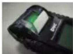
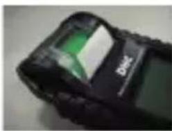
REPLACING PAPER

natural_image
Close-up of a black electronic device with a green plastic clip inserted, no visible text or symbolsA. Open the transparent cover.

natural_image
Close-up of a black electronic device with a green circuit board and a white cylindrical component (no visible text or symbols)B. Place a new roll of paper in the compartment. Reference paper : 056237 or 056633
natural_image
Close-up of a black electronic device with green and white modules (no visible text or symbols)C. Place a small length of paper from the compartment and press the transparent cover to close.
DATA RECORDING ON PC
- Insert the CD into the drive.
- Follow the installation instructions and install the «Decode_BT2010WWWVxx» icon. The table below is displayed.
- Enter the test code into the table manually or by a scanned bar code.
- The test result appears in a table.
- The data can be recorded on PC.
MAINTENANCE
| Examples Solutions | |
| Display switched off | Check that the device is connected to the battery. The battery voltage is not high enough to perform the test (<1.0 V). Fully charge the battery and try again. |
| Printing fault Paper jam: the paper is not inserted correctly. Out of print paper: Insert paper. | |
| Insufficient internal battery Replace the batteries in the tester. | |
WARRANTY
The warranty covers faulty workmanship for 2 years from the date of purchase (parts and labour).
The warranty does not cover:
- Transit damage.
- Normal wear of parts (eg. : cables, clamps, etc..).
- Damages due to misuse (power supply error, dropping of equipment, disassembling).
- Environment related failures (pollution, rust, dust).
In case of failure, return the unit to your distributor together with:
- The proof of purchase (receipt etc ...)
- A description of the fault reported
natural_image
Close-up of a black electronic device with a green plastic clip inserted, showing no visible text or symbols.natural_image
Close-up of a black electronic device with a green component and a white cylindrical body (no visible text or symbols)natural_image
Close-up of a black electronic device with green and white visible components (no readable text or symbols)natural_image
Close-up of a handheld device with a green and white component being inserted (no visible text or symbols)natural_image
Close-up of a black electronic device with a green component and a white body (no visible text or symbols)