
Stella 3201 - Barbecue BARBECOOK - Free user manual and instructions
Find the device manual for free Stella 3201 BARBECOOK in PDF.
| Product Type | Gas Barbecue |
| Brand | Barbecook |
| Model | Stella 3201 |
| Fuel | Butane or propane gas (4.5 to 15 kg bottle) |
| Gas pressure (depending on country) | 28-30 mbar (butane) or 37 mbar (propane) |
| Main burners | Yes |
| Side burner | Yes (max 9 kg, max Ø 220 mm) |
| Ignition | Electric (AA battery not included) or by match |
| Grill material | Enamelled cast iron |
| Material of the tank and lid | Enamelled steel |
| Thermometer | Yes, on the lid |
| Heat zones | Yes (front, middle, back) |
| Cooking methods | Direct and indirect |
| Maintenance | Regular cleaning of the grill, tank, burners and Venturi tubes |
| Safety | Gas leak detection, outdoor use only, never leave unattended |
| Warranty | 5 years on tank, lid, burners and enamelled cast iron grills; 2 years on other parts |
| Spare parts | Available through dealer (serial number required) |
| Storage | Dry place, disconnect the gas bottle, cover recommended |
| Gas bottle | Propane or butane, max height 70 cm |
| Gas hose | Max 1.5 m, approved according to country |
| Igniter battery | AA (not included) |
| Use | Outdoor only, flat and stable surface |
| Standards | Regulator complies with EN 16129 |
Frequently Asked Questions - Stella 3201 BARBECOOK
User questions about Stella 3201 BARBECOOK
0 question about this device. Answer the ones you know or ask your own.
Ask a new question about this device
Download the instructions for your Barbecue in PDF format for free! Find your manual Stella 3201 - BARBECOOK and take your electronic device back in hand. On this page are published all the documents necessary for the use of your device. Stella 3201 by BARBECOOK.
USER MANUAL Stella 3201 BARBECOOK
Register your Barbecook® on www.barbecook.com and enjoy the full Barbecook® experience!

THIS IS YOUR UNIQUE SERIAL N°
NL - GEBRUIKSAANWIJZING 4
FR - GUIDE D'UTILISATION 14
EN - USER GUIDE 25
DE – BENUTZERHANDBUCH 35
ES - MANUAL DE USUARIO 46
IT - GUIDA PER L'UTENTE 57
PT - GUIA DO UTILIZADOR 68
SV - BRUKSANVISNING 78
natural_image
Technical line drawing of a mechanical device with two views: top shows a cylindrical component being inserted, bottom shows a circular component with a handle (no text or symbols)natural_image
Technical line drawing of a mechanical component with three top views and a downward arrow indicating process (no text or symbols)4.3. Email
natural_image
Technical line drawing of a portable grill with handle and control panel (no text or symbols)6.3.1. Koppeling A
natural_image
Technical diagram of a mechanical assembly with threaded components and an upward arrow indicator (no text or labels)
natural_image
Mechanical diagram showing a screw being inserted into a housing with an arrow indicating rotation (no text or symbols present)natural_image
Technical diagram of a mechanical assembly with a threaded component and an upward arrow indicator (no text or symbols present)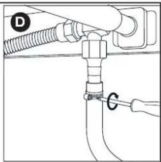
text_image
D G6.3.2 Koppeling B
natural_image
Mechanical diagram showing a lever mechanism with a curved arrow indicating rotational motion (no text or symbols present)natural_image
Mechanical assembly diagram showing a valve with threaded port and connector (no text or symbols)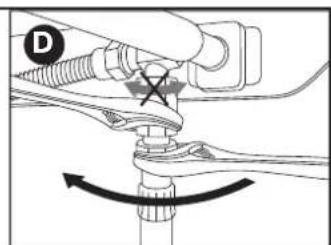
natural_image
Mechanical diagram showing a valve assembly with a cross mark and curved arrow indicating rotation (no text or symbols)natural_image
Technical line drawing of a mechanical assembly with no visible text or symbols
natural_image
Line drawing of a mechanical device with no visible text or symbolsnatural_image
Line drawing of a toothbrush with 'barbecook' branding on the lid (no additional text or symbols)natural_image
Pure technical diagram of a pipe joint with a circular valve, no text or symbols present
natural_image
Simple line drawing of a hand holding a tool with a cross mark and droplet shape (no text or symbols)natural_image
Line drawing of a gas cylinder with two arrows indicating direction (no text or symbols)
text_image
barbecook B
text_image
barbe C
text_image
D ! barbecook
natural_image
Diagram of a mechanical component with a shaft and housing, showing a directional arrow (no text or symbols)
natural_image
Simple line drawing of a string with two circular ends and a dot at the end (no text or symbols)natural_image
Line drawing of a vehicle interior showing a fire extinguisher and its internal compartments (no text or symbols)natural_image
Line drawing of a portable stove interior with a fire extinguisher being inserted (no text or symbols)natural_image
Diagram of a bottle with internal spiderweb structure and two butterflies (no text or labels)
natural_image
Technical line drawing of a mechanical assembly with three curved components and rotational arrows indicating motion (no text or symbols)natural_image
Technical line drawing of a mechanical device with two views: top shows a cylindrical component being inserted, bottom shows a flanged component with a handle (no text or symbols)natural_image
Technical line drawing of a mechanical component with three top views and a downward arrow indicating process (no text or symbols)4.3. Émail
natural_image
Technical line drawing of a portable grill with handlebars and control panel (no text or symbols)6.3.1. Raccord A
natural_image
Mechanical diagram showing a threaded fastener inserted into a pipe, with an upward arrow indicating force direction (no text or symbols present)
natural_image
Mechanical diagram showing a screw being inserted into a housing with an arrow indicating rotation (no text or symbols present)natural_image
Technical diagram of a mechanical assembly with a threaded component and an upward arrow indicator (no text or symbols present)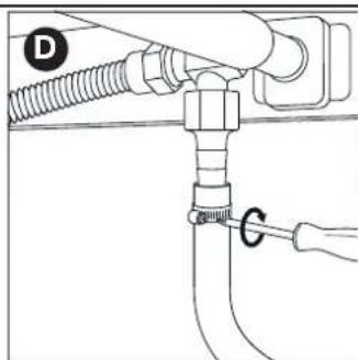
text_image
D G6.3.2 Raccord B
natural_image
Diagram of a mechanical assembly with threaded pipe and valve, showing upward force indicator (no text or symbols)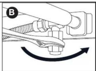
natural_image
Mechanical diagram showing a lever mechanism with a curved arrow indicating rotational motion (no text or symbols present)text_image
Technical diagram showing two mechanical assembly states labeled C and D, with arrows indicating movement or force direction.natural_image
Technical line drawing of a mechanical assembly with no visible text or symbols
natural_image
Line drawing of a medical device with a cap and tubing (no text or symbols)natural_image
Line drawing of a toothbrush with 'barbecook' branding on the lid (no additional text or symbols)natural_image
Line drawing of a mechanical component with a circular checkmark indicating a detail (no text or symbols present)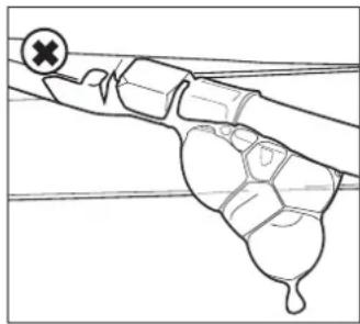
natural_image
Diagram of a mechanical or biological structure with a cross mark and a droplet, no text or symbols presentnatural_image
Line drawing of a gas cylinder with a car on top, showing internal structure and two arrows pointing to the side (no text or symbols)
text_image
barbecook B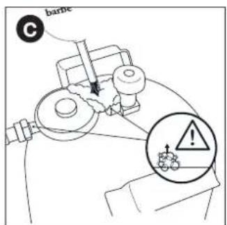
text_image
C barbe
text_image
D ! barbecooknatural_image
Diagram of a mechanical component with a shaft and pin, showing a directional arrow (no text or symbols)natural_image
Simple line drawing of a mechanical lever or rod with two circular ends and a central dot (no text or symbols)natural_image
Line drawing of a vehicle interior with a black arrow indicating a component or motion direction (no text or symbols present)natural_image
Line drawing of a portable stove interior with a fire extinguisher being inserted (no text or symbols)natural_image
Diagram of a bottle with internal geometric patterns and two spider-like shapes inside (no text or symbols)natural_image
Technical line drawing of a mechanical assembly with three curved components and directional arrows indicating motion (no text or symbols)Thank you for purchasing a Barbecook barbecue. We hope you enjoy using it and have many happy times with it! You can optimize your experience by registering your barbecue online to take advantage of the many benefits.
- You gain access to the full online user guide, so you can learn the ins and outs of your appliance.
- We provide you with personalized after-sales service, which means you can quickly and easily find and order spare parts. This enables you to get the most out of the warranty service.
- You are kept informed of product updates.
- You learn many new tips and tricks.

For more information about registering your appliance, visit www.barbecook.com.

Barbecook respects your privacy. Your data will never be sold, distributed, or shared with third parties.
2. ABOUT THIS GUIDE
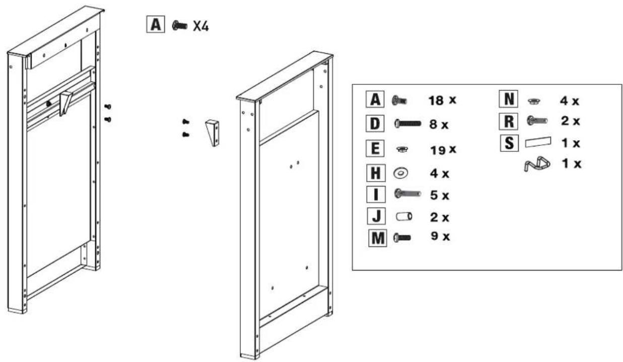
This guide consists of 2 parts. Part 1 contains general instructions on assembly, use, maintenance, and warranty. Part 2 (beginning on page 88) contains illustrations, lists of parts, and assembly drawings.

If there is an illustration that corresponds to a specific instruction in the guide, you will be referred to it with this pictogram of a pencil.
3. IMPORTANT SAFETY INSTRUCTIONS
3.1. Read and follow these instructions
Read the instructions before using the appliance Always follow the instructions carefully. Assembling or using the appliance in a way that deviates from the instructions may result in fire and material damage.

Damage caused as a result of a failure to follow the instructions
(improper assembly, misuse, improper maintenance, etc.) is not covered by the warranty.
3.2. Exercise caution when handling gas
Working with gas is safe provided that you take some precautions:
- Always store gas bottles outside of the home in a well-ventilated space. Ensure that the bottles are not exposed to high temperatures or to direct sunlight.
- Never store your gas bottle or spare gas bottle in the cabinet of your appliance.
- Never store your spare gas bottle in the vicinity of a gas appliance that is in use.
• After use, always close the gas supply at the gas bottle. - Never smoke in the vicinity of a gas-operated appliance that is in use, nor in the vicinity of a gas bottle, empty or full.

If you smell gas, close the gas supply immediately, extinguish all flames, and open the lid on the appliance. If the smell persists, call your gas supplier or the fire service.
3.3. Choosing a suitable location
Only use the appliance outside. If you use the appliance inside, even in a garage or shed, you risk carbon monoxide poisoning. Take into account the following when choosing a location: Place the appliance at least three meters from a building in an open, well-ventilated location.
- Ensure that there is always plenty of unobstructed air to the
burners and to the ventilation openings in the cabinet.
- Do not place the barbecue below an overhanging structure (veranda, shelter, etc.) or under foliage.
- Place the appliance on a sturdy and stable surface. Do not place the appliance on a moving vehicle (boat, trailer, etc.).
3.4. Safety instructions
- Only use outside.
- Read the instructions before use.
- Do not move the appliance during use.
- Never leave the appliance unsupervised during use, and particularly if there are children or animals around.
- WARNING: Touchable parts can become very hot. Keep young children away.
- Use appropriate protection when you need to touch hot parts (lid, grill, etc.).
- Keep the appliance away from flammable materials when in use.
- Keep flammable materials, flammable liquids and, soluble objects a safe distance from the appliance when in use.
- Do not use wood, charcoal, lava stone, or ceramic briquettes in a gas appliance.
- Do not use the appliance when under the influence of alcohol or drugs.
- Close the gas supply on the gas bottle after use.
- Do not modify the appliance.
4. RECURRENT CONCEPTS
This part of the guide lists the definitions of some less familiar concepts. These concepts are used when discussing various topics throughout the guide.
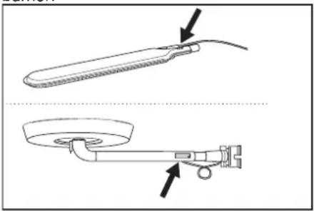
4.1. Venturi tubes
The venturi tubes are the small tubes attached at the inlet to the burners. There is an opening on the side of the venturi tubes. This is visible on the main burners and on the side burner:
natural_image
Technical line drawing of a mechanical device with two views: top shows a tool handle, bottom shows a base with a knob and lever (no text or symbols)The gas passes through the venturi tubes on its way to the burners. The gas is mixed with air (and, therefore, oxygen) through the openings in the sides. This is essential for proper combustion in the burners: proper combustion requires the correct gas/oxygen mix to deliver nice flames.
4.2. Burner covers
The burner covers are covers fitted on top of the burners on the barbecue. They protect the burners from dripping fat and play a crucial role in use of the barbecue. The covered openings on the sides of the covers distribute the heat over the grill so that it heats up more quickly and more evenly.

Pay particular attention to the burner covers when assembling the barbecue. Heat distribution is optimal when each cover is fitted over the correct burner.

natural_image
Technical line drawing of a mechanical component with three top views and a downward arrow indicating assembly or disassembly (no text or symbols present)4.3. Enamel
Some parts of the appliance are covered in a layer of melted glass, also known as enamel. This enamel protects the underlying metal from corrosion. Enamel is a high-quality material: it is corrosion-resistant, it does not degrade under the influence of high temperatures, and it is very easy to maintain.

Since the enamel is less flexible than the metal to which it is applied, pieces of enamel may break off when the appliance is used incorrectly. To avoid this problem, you must be careful when assembling enameled parts and you must always maintain the enamel according to the instructions in this guide.
4.4. Flare-ups
Flare-ups are sudden flames that spark from the bowl when you are grilling. They are usually caused by dripping fat or marinade.
5. ASSEMBLING THE APPLIANCE
5.1. Safety instructions
- Do not make modifications to the appliance when assembling. Parts pre-fitted and/or sealed by the manufacturer must not be modified as doing so presents a hazard.
• Always follow the assembly instructions carefully. - The user is responsible for the correct assembly of the appliance. Damage caused by incorrect assembly is not covered by the warranty.
5.2. To assemble the appliance
You require a Phillips screwdriver, a flat-head screwdriver, and an AA battery (for the electrical igniter). The appliance is not
supplied with batteries.
- Place the appliance on a flat and stable surface.
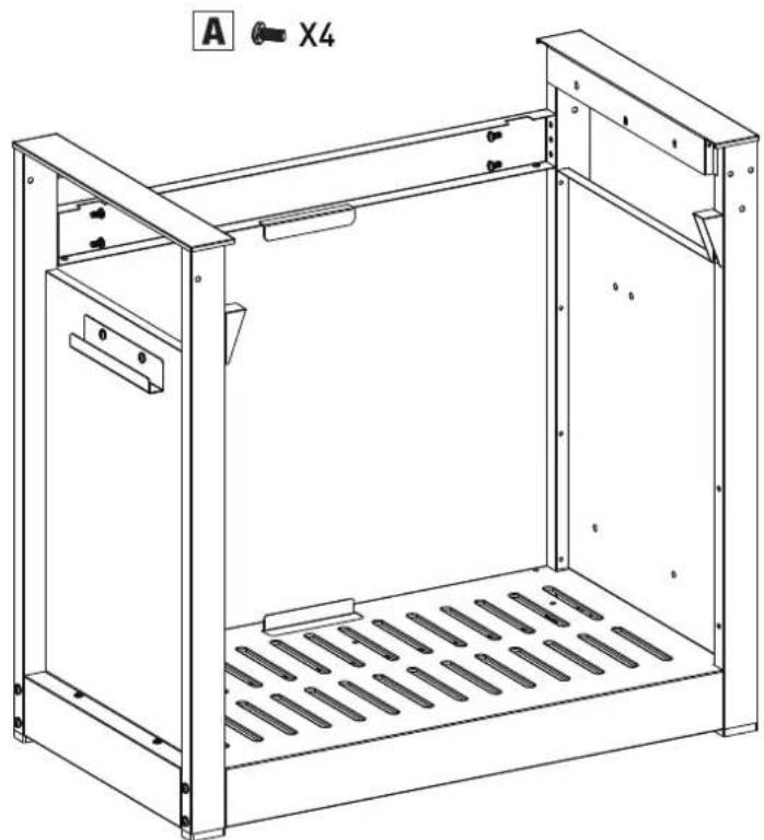
- Assemble the appliance as shown in the assembly drawings.

You can find the assembly drawings in the second part of this guide, after the exploded drawing of your appliance (see page 90).

Take care when assembling enameled parts. The tool and the screws may damage the enamel. Use the fiber washers supplied to protect the enamel around the screws.

The blister packaging may contain more screws than needed, in which case there will be some screws left over after assembly.
6. FITTING THE APPLIANCE WITH GAS
6.1. Which gas bottle, hose, and regulator?
To fit the appliance with gas, you will firstly need to purchase a gas bottle, a hose, and a pressure regulator. The table below indicates which gas bottle, hose, and regulator you should use. In Belgium (BE), for example, you must use a propane bottle with a hose and regulator for 37 mbar, or a butane bottle with hose and regulator for 28-30 mbar.
| Country | Gas bottle, hose, and regulator |  | |
| LU - NL - DK - FI- SE - CY - CZ -EE - LT - MT - SK- SI - BG - IS - NOTR - HR - RO - IT- HU - LV | 28-30 mbar | propane,butaneor theirmixtures | |
| BE - FR - IT - LU -IE - GR - PT - ES- CY - CZ - LT -SK - CH - SI - LV | 28-30 mbar | butane | |
| 37 mbar propane | |||

The appliance has been designed to be used with butane or propane bottles of 4.5 to 15 kg and equipped with an appropriate reducer valve. We recommend using propane with the appliance. Propane delivers high-quality combustion and is less sensitive to frost. The height of the gas bottle must not exceed 70 cm, irrespective of the width or diameter D or the bottle.

Always purchase your pressure regulator and gas bottle together. Not all regulators fit all gas bottles.

Use only a gas hose and regulator with homologation for the country of use.
6.2. Safety instructions
- Never connect the gas hose directly to the appliance. Always fit a pressure regulator to the gas bottle first.
- Never modify pre-assembled or sealed parts of the gas bottle, hose, or pressure regulator.
- Ensure as short a hose as possible (max. 1.5 m) to prevent it being dragged over the ground.
- Never deform or fold/crease the gas hose. Check that the hose is neither stretched nor twisted. Ensure that the hose does not come into contact with parts that could become
hot.
- The hose must be replaced if it becomes damaged or shows signs of tearing, if national regulations stipulate this or in accordance with their applicability.
• The gas bottle must always be upright.
- Check for gas leaks whenever you make modifications to gas connections. See "7.5. Checking for gas leaks".
6.3. Connect the hose to the appliance
France:
The appliance can be used with 2 types of gas hose.
- Gas hose to be attached to the hose tails on the appliance and on the pressure regulator, secured with hose clamps (in accordance with XP D 36-110). Recommended length 1.25 m
- Gas hose (in accordance with XP D 36-112) equipped with a nut G 12 for direct connection to the appliance and a nut M20 x 1.5 m for direct connection to the pressure regulator, recommended length 1.25 m.
Other countries:
A flexible hose suitable for butane or propane gas is recommended. The hose must not be longer than 1.50 m. To be able to connect the gas hose to the appliance, fit a coupling to the gas tube on the appliance. The appliance is supplied with two different couplings intended for use in different countries.
| Country Coupling | |
| BE, CH, CZ, DK, ES, FI, GB, IE, IT, PT, SI | Coupling A |
| FR Coupling B |

If your country is not listed in the table, use the coupling that meets the standards that apply in your country.

natural_image
Technical line drawing of a portable grill with handlebars and control panel (no text or symbols)6.3.1. Coupling A
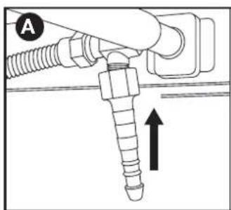
You require a 19 mm wrench and a Phillips screwdriver.
- Screw the coupling onto the gas tube on the appliance (A) and tighten it with a 19 mm wrench (B).
natural_image
Mechanical diagram showing a threaded fastener inserted into a pipe with an upward arrow indicating force (no text or symbols present)
natural_image
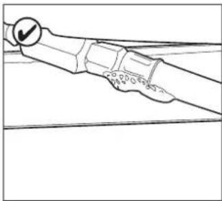
Mechanical diagram showing a screw being inserted into a housing with an arrow indicating rotation (no text or symbols present)- Slide the hose over the coupling (C) and tighten the clamping ring with a Phillips screwdriver (D).
TIP: Apply a small amount of dish soap to the coupling and heat the end of the gas hose with a hair drier so that it slides smoothly over the coupling.

text_image
Technical diagram showing two installation steps of a pipe fitting with labeled components (C, D, G) and an upward arrow indicating direction.6.3.2 Coupling B
You require a 22 mm wrench and an adjustable wrench.
- Screw the coupling onto the gas tube on the appliance (A) and tighten it with a 22 mm wrench (B).

natural_image
Diagram of a mechanical assembly with threaded pipe and valve, showing upward force indicator (no text or labels)
natural_image
Mechanical diagram showing a lever mechanism with a curved arrow indicating rotational motion (no text or symbols present)- Screw the gas hose onto the coupling (C) and secure it with two wrenches. Hold the coupling firm with one 22 mm wrench and tighten the hose with an adjustable wrench.

natural_image
Mechanical assembly diagram showing a pipe fitting with a valve and directional arrow (no text or symbols)
natural_image
Mechanical diagram showing a valve assembly with a rotating knob and adjustment mechanism (no text or symbols)6.4. Connect the hose and gas bottle to the regulator.
You will require a Phillips screwdriver and/or an adjustable wrench depending on the type of regulator that you are using.
-
Connect the hose to the pressure regulator. Proceed as follows:
-
If the hose is fitted with a clamping ring, slide the hose over the regulator and tighten the clamping ring with a Phillip screwdriver (A).
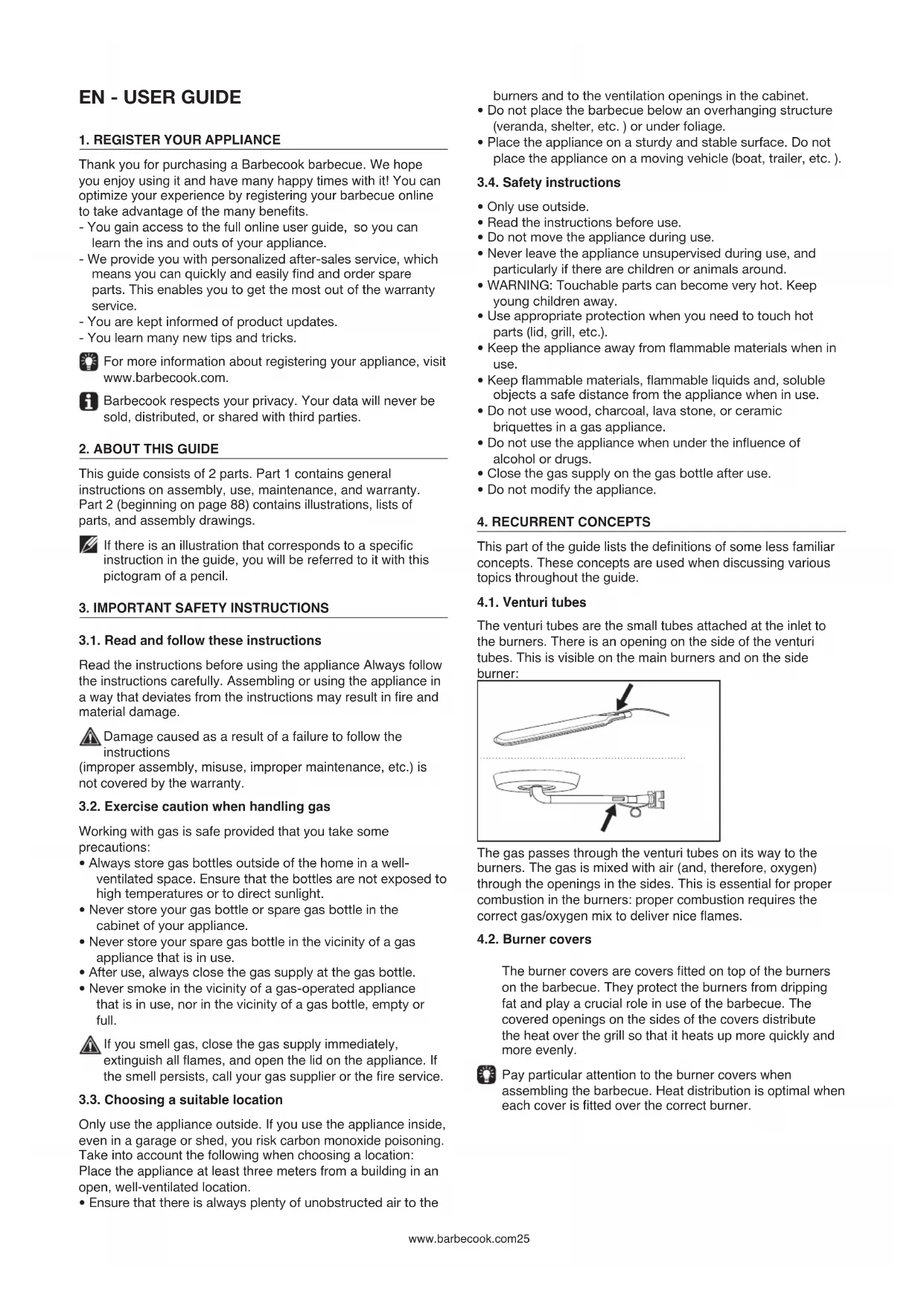
- If the hose is fitted with a nut, screw the hose onto the regulator and tighten the nut with and adjustable wrench (B).
- Connect the pressure regulator to the gas bottle. Proceed as follows:
- If the regulator is fitted with a nut, screw the regulator onto the gas bottle clockwise and tighten the nut with an adjustable wrench (C).

natural_image
Technical line drawing of a mechanical assembly with no visible text or symbols
natural_image
Line drawing of a mechanical device with no visible text or symbols- If the regulator has a thread, screw the regulator onto the gas bottle counter-clockwise (D)

Only use regulators that satisfy EN 16129.
6.5. Replace the gas bottle
- Close the gas supply and set all control knobs to OFF.
- Disconnect the empty gas bottle and connect the full gas bottle.
- Check the gas bottle, the hose, and all gas connections for leaks. See "7. Checking for gas leaks".

Note that when replacing the gas bottle, you must always be well away from sources of ignition.
7.1. Why check for gas leaks?
Propane and butane are both heavier than air. This means that these gases will not drift away if they leak from the appliance. On still days, leaked gas can accumulate in and around the appliance and subsequently ignite and explode.
7.2. When to check for gas leaks?
- Before first use or after a lengthy period out of use.
Check that there are no gas leaks if the appliance has been assembled by the supplier. - You should you do this whenever you replace a gas part.
- At least once annually, ideally at the start of the season.

7.3. Safety instructions
- Place the appliance outside in a well-ventilated location. Ensure that there are no flames or heat sources in the vicinity of the appliance.
- Never use a lighter or matches to check for gas leaks.
- Do not smoke or ignite the burners when checking for gas leaks.
7.4. What materials do I need?
To check for gas leaks, you require the following:
- A test fluid. You can use a ready-to-use leak spray or mixture of water (50%) and dish soap (50%).
- The leak testing tool supplied with the appliance. This fluid is used to suction up the test fluid and apply it to the gas parts or gas connections that you want to check.

natural_image
Line drawing of a toothbrush with 'barbecook' text on the head (no other text or symbols)7.5. Check for gas leaks
You can check for gas leaks by applying a test fluid to all gas parts and gas connections. If there are large bubbles on a specific part or connection, there is a gas leak.
natural_image
Pure mechanical diagram showing a lever and pivot point without any text, numbers, or symbols
natural_image
Diagram of a hand holding a small object with a cross symbol, no text or labels presentProceed as follows to check for gas leaks:
- Place the appliance outside.
- Take the leak testing tool and test fluid (leak spray or water/dish soap mix)
- Open the lid and set all control knobs to OFF.
-
Open the gas supply slightly. To do this, turn the valve on the gas supply just once.
-
Suction a small amount of test fluid with the leak testing tool and apply it to the zone that you want to check. The following parts must be checked:
• The weld seams on the gas bottle (A)
- The hose (B)
- The connections between the gas bottle and the pressure regulator and between the pressure regulator and the hose (C)
• The connection between the hose and the appliance (D)

natural_image
Line drawing of a gas cylinder with two arrows indicating flow direction (no text or symbols)
text_image
barbecook B
text_image
C barbie
text_image
D barbecook
The pressure regulator and coupling on your appliance may differ from the examples in the figures.
-
Proceed as follows:
-
If you detect a leak, follow the instructions in "7.6 In the event of a gas leak".
- If there are no leaks, close the gas supply, rinse all parts thoroughly with water, and dry them well.
7.6. In the event of a gas leak
- Close the gas supply and proceed as follows:
- If you have detected a leak on one of the connections, firmly tighten the connection in question.
- If you have detected a leak on the gas bottle or hose, replace the gas bottle or hose.
-
Check the connection or part where you detected the leak again.
-
If the leak has not been fixed, you must contact a Barbecook dealer. You must not start using the appliance until the leak has been fixed.

Consult www.barbecook.com or a list of
Barbecook dealers near you.
8. PREPARING THE APPLIANCE FOR USE
8.1. Before each use
Whenever you use the appliance, you must ensure that:
- The appliance is set up in a suitable location See "3.3 Choosing a suitable location".
- The hose does not drag over the ground and cannot come into contact with hot surfaces or dripping fat.
- The bowl is clean. We recommend cleaning the bowl after every use. See "11.2 Cleaning the bowl".
- The burners and venturi tubes are not blocked by insect nests or spider webs. See "11.3 Cleaning the burners and venturi tubes".
- The burners are correctly fitted. The venturi tubes must be situated above the openings of the gas valves.

natural_image
Diagram of a mechanical component with a shaft and housing, showing an arrow indicating direction (no text or symbols present)
To be absolutely certain that the gas connections are in order, you can check the appliance for gas leaks before each use. See "7. Checking for gas leaks".
8.2. Before first use (or after a lengthy period out of use)
If you are using the appliance for the first time or after a lengthy period out of use, you must carry out some additional checks:
- Ensure that you have read all of the instructions in this guide, understood them, and checked them (before first use only).
- Check the appliance for gas leaks. See "7. Checking for gas leaks".

Check that there are no gas leaks if the appliance has been assembled by the supplier.
- Clean the burners and venturi tubes (only after a lengthy period out of use). See "11.3 Cleaning the burners and venturi tubes".
- Allow the appliance to "burn in" before placing any food on the grill (only before first use). See "8.3 Burning in the appliance".
8.3. Burning in the appliance
Burning in the appliance before first use helps to remove any manufacturing greases that may still be present. Proceed as follows:
-
Ignite the main burners and set the control knobs to HIGH. See "9.2 Igniting the main burners".
-
Close the lid and allow the appliance to burn for 15 minutes. Do not put any food on the grill yet.
-
After 15 minutes, open the lid and let the appliance burn for a further 5 minutes (control knobs still set to HIGH).
-
After these 5 minutes, the appliance is ready for use and you can place food on the grill.
9. IGNITING THE BURNERS

To ignite the burners with the electric igniter, you must insert an AA battery into the igniter. The battery is not
supplied with the appliance. The battery compartment is located at the back of the cabinet on the appliance.
9.1. Safety instructions
- Before igniting the appliance, carry out all checks as specified in "8. Preparing the appliance for use".
- Ensure that the lid is open whenever you ignite a burner.
- Never bend directly over a burner when igniting it.
9.2. Igniting the main burners
9.2.1 Using the igniter
- Open the lid and set the control knobs for the main burners to OFF.
- If no other burner has yet been ignited, open the gas supply and wait for ten seconds for the gas to stabilize.
- Press the control knob for a burner, set it to HIGH, and leave it in place. The in-built igniter will create sparks, which will ignite the burner. ⚠️ Start by igniting one main burner first. Never ignite all main burners at the same time.
- If the burner does not ignite after three attempts, set the control knob for the burner to OFF, close the gas supply, and wait for 5 minutes to allow the accumulated gas to escape.
- Attempt to ignite the burner again. If it still does not ignite, attempt to ignite the burner with a match or consult "14. Rectifying problems" in order to identify the cause of the problem.
9.2.2 Using a match
- Place a match in the match holder.

natural_image
Simple line drawing of a string with two circular ends and a dot at the end (no text or symbols)- Open the lid and set the control knobs for the main burners to OFF.
- If no other burner has yet been ignited, open the gas supply and wait for ten seconds for the gas to stabilize.
- Strike the match and hold it around 13 mm away from the burner.
natural_image
Technical line drawing of a mechanical component with internal compartments and a directional arrow (no text or symbols)- Set the control knob for one burner to HIGH. Start by igniting one main burner first. Never ignite all main burners at the same time.
- If the burner does not ignite within 5 seconds, set the control knob for the burner to OFF, close the gas supply, and wait for 5 minutes to allow the accumulated gas to escape.
- Attempt to ignite the burner again. If this does not work,
consult "14. Rectifying problems" in order to identify the cause of the problem.
- If one burner has been ignited, you can ignite the other burners by setting the relevant control knobs to HIGH.
9.3. Igniting the side burner

The side burner can only hold pans with a maximum weight of 9 kg and a maximum diameter of 220 mm.

The lid on the side burner must remain open when the side burner is in use.
9.3.1 Using the igniter
- Open the lid and set the control knob for the side burner to OFF.
- If no other burner has yet been ignited, open the gas supply and wait for ten seconds for the gas to stabilize.
- Press the control knob for the side burner, set it to HIGH, and leave it in place. The in-built igniter will create sparks, which will ignite the side burner.
- If the burner does not ignite after three attempts, set the control knob for the burner to OFF, close the gas supply, and wait for 5 minutes to allow the accumulated gas to escape.
- Attempt to ignite the side burner again. If it still does not ignite, attempt to ignite the burner with a match or consult "14. Rectifying problems" in order to identify the cause of the problem.
9.3.2 Using a match
- Place a match in the match holder.
- Open the lid and set the control knob for the side burner to OFF.
- If no other burner has yet been ignited, open the gas supply and wait for ten seconds for the gas to stabilize.
- Strike the match and hold it around 13 mm away from the side burner.

natural_image
Line drawing of a toaster oven with a handle and cooling grille (no text or symbols)- Set the control knob for the side burner to HIGH.
- If the side burner does not ignite within 5 seconds, set the control knob for the burner to OFF, close the gas supply, and wait for 5 minutes to allow the accumulated gas to escape.
- Attempt to ignite the side burner again. If this does not work, consult "14. Rectifying problems" in order to identify the cause of the problem.
9.4. Switching the burners off
If the burners will not be used for some time, they must be switched off. Proceed as follows:
- Close the gas supply.
- Set the control knobs for the burners to OFF.

By closing the gas supply first, you ensure there is no longer any gas present in the appliance.
9.5. Re-igniting the burners
If a burner goes out in use, proceed as follows:
- Open the lid and close the gas supply.
- Set all control knobs to OFF and wait for 5 minutes for the accumulated gas to escape.
- Re-ignite the burner(s).
9.6. Checking the flames
Whenever you ignite a burner, you must check its flames. A perfect flame will be almost blue, with a small amount of yellow at the top. Sporadic yellow flames are normal and safe. If there is a problem with the flames, take one of the following measures to rectify it:
| The flames are... Proceed as follows... | |
| Low and entirely yellow 1. | Close the gas supply immediately and set all control knobs to OFF.2. Consult "14. Rectifyingproblems" in order to identifythe cause of the problem. Theventuri tubes are most likelyblocked. |
| Higher than the bowl 1. | Close the gas supplyimmediately and set all controlknobs to OFF.2. Wait for 5 minutes to allow theaccumulated gas to escape.3. Re-ignite the burner(s).4. If this does not rectify theproblem, consult "14. Rectifyingproblems" in order to identify thecause. |

text_image
LOW HIGH10. USEFUL TIPS AND TRICKS
10.1. Pre-heating the appliance
Pre-heating the appliance ensures that the grill is hot enough when you come to place food on it. Proceed as follows:
- Ignite the burner(s) and set the control knob(s) to HIGH.
- Close the lid and allow the appliance to burn for ten minutes.
- After ten minutes, open the lid and place the food on the grill.
- If you want less heat, set the control knob(s) to a lower heat.
10.2. Preventing food from sticking
To prevent your food from sticking to the grill:
- Oil the food lightly with a brush before placing it on the grill. You can also oil the grill itself.
- Pre-heat the appliance. The hotter the grill when you place the food on it, the less the chance of the food sticking.
- Do not turn the food too quickly. First allow it to heat up thoroughly.
10.3. Grilling directly and indirectly
You can grill directly or indirectly depending on the type of food that you want to cook and the way in which you want to do it:
| Method Description Use | ||
| Directly Place the food immediately above an ignited burner, choose a high heat with the control knob for the burner, and leave the lid open. | Searing meat and vegetables | |
| Indirectly | Place the food next to an ignited burner, choose a medium/low heat with the control knob, and close the lid. | Pre-cook meat or further cook seared meat. |
If grilling with the lid closed, you must keep an eye on the lid thermometer to ensure that the appliance does not become too hot. See "10.5 Checking the temperature".
10.4. Grilling with the lid closed
There are a number of benefits of grilling with the lid closed.
- The temperature of the grill will be higher and remain more consistent.
- The food will need to cook for less time and will remain more succulent.
- There will be fewer flare-ups and gas consumption will be lower.
If grilling with the lid closed, you must keep an eye on the lid thermometer to ensure that the appliance does not become too hot. See "10.5 Checking the temperature".
10.5. Checking the temperature
The appliance is equipped with powerful burners, which means that you will be able to heat them up quickly, and can maintain a constant temperature. However, if you grill with the lid closed, you will need to ensure that the appliance does not become too hot. You should check the lid thermometer regularly and take the following guidelines into account:
- A normal operating temperature is around 210°C. If the temperature is higher, there is a risk of dripping and caked fat igniting.
- The temperature must not exceed 300^ C for more than five minutes. If it does, there is a risk of the appliance being damaged and becoming deformed.
If the appliance becomes too hot, allow it to cool by opening the lid, and choose a lower heat for the burners.
10.6. Using the heat zones
Once all burners have been ignited, the burner covers distribute the heat as evenly as possible over the grill. Even though heating is as even as possible, some zones will be warmer than others. You can use these heat zones for perfect grilling:
| Zone Warm Use for... | |
| For Warm Grilling delicate foods(shrimps, fish, etc.) | |
| Middle Warmer Preparing foods that need to cook for longer (sausages, chicken, etc.) | |
| Rear Warmest Searing meat and vegetables |
You can also create heat zones by playing with the power of the burners. For example, you could set a burner at a lower level and use the zone above the burner for delicate foods or foods that need to cook for longer.
10.7. Preventing flare-ups
Flare-ups may occur when grilling. This is a normal occurrence. However, an excess of flare-ups increases the temperature of
the appliance and can ignite accumulated fat.
Preventing flare-ups:
- Ensure that the bowl is clean before you start grilling. See "11.2 Cleaning the bowl".
- Check that the fat drain opening is clear at regular intervals and/or that the fat drip drawer is not full.
- When grilling, cut excess fat away from meat, close the lid, and set the burners to a medium or low heat.
11. MAINTAINING THE APPLIANCE
11.1. Cleaning the grill
We recommend cleaning the grill after each use with a Barbecook accessory.
You can also clean the grill with a mild cleaning agent or sodium bicarbonate. Never use oven cleaners to clean the grill.
11.2. Cleaning the bowl
We recommend cleaning the bowl after each use with a Barbecook accessory, metal sponge, and abrasive cleaning agent. Use these in the same way as for the grill.
Do not use any sharp objects and do not knock the appliance against hard surfaces.
Avoid contact with cold liquids while the appliance is still hot.
11.3. Cleaning the burners and venturi tubes
11.3.1. Why clean the burners and venturi tubes?
Spiders and insects can make webs and nests in the burners and venturi tubes, blocking the gas supply to the burners. Consequence:
- You cannot ignite the burners. If you do manage to ignite the burners, they will only produce smoky, yellow flames.
- The gas can ignite outside of the venturi tubes level with the control knobs. These flames are known as flashbacks and can cause serious injury and material damage.

natural_image
Diagram of a bottle with internal spiderweb structure and two butterflies (no text or symbols)i Damage as a result of blocked burners and venturi tubes is considered poor maintenance and is not covered by the warranty.
11.3.2. When to clean the burners and venturi tubes?
Clean the burners and venturi tubes on the appliance as follows:
- Before first use after a lengthy period out of use.
- At least twice annually, once at the start of the season.
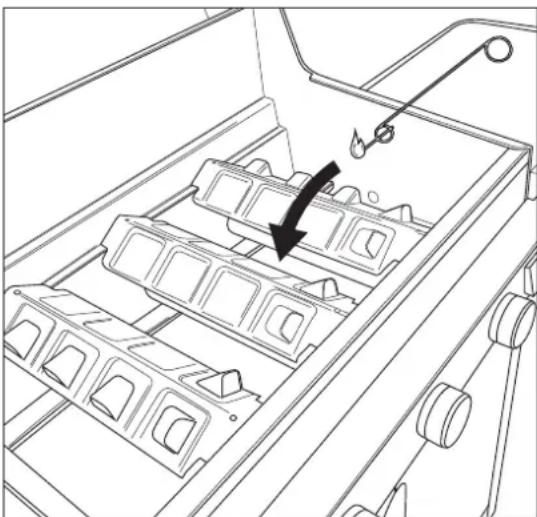
11.3.3. Cleaning the burners and venturi tubes
- Remove the burners from the appliance as shown in the figures. If you notice that a burner is damaged, you must replace it.
- Clean the burners and venturi tubes with a small brush of self-made pipe cleaner (an opened paper clip, pipe brush, etc.).
- Put the burners back in place. Ensure that the venturi tubes are situated above the openings of the gas valves.

natural_image
Technical line drawing of a mechanical assembly with three curved components and rotational arrows indicating motion (no text or symbols)11.4. Maintaining enamel, stainless steel, and powder coated parts
The appliance comprises enamel, stainless steel, and powder coated parts. Each material must be maintained differently:
| Material How to maintain this material | |
| Enamel | Do not use any sharp objects and do not knock the appliance against hard surfaces.Avoid contact with cold liquids while the appliance is still hot.You can use metal sponges and abrasive cleaning products. |
| Stainless steel | Do not use aggressive, abrasive, or metal cleaning agents.Use mild cleaning agents and leave to work on the steel.Use a soft sponge or cloth.After cleaning, rinse the appliance thoroughly and allow the appliance to dry completely before storing. |
| Powder coated | Do not use sharp objects. Use mild cleaning products and a soft sponge or cloth.After cleaning, rinse the appliance thoroughly and allow the appliance to dry completely before storing. |
To prevent rust formation on stainless steel parts, it is best to avoid contact with chlorine, salt, and iron.
Damage that arises as a result of not following these instructions is considered poor maintenance and is not covered by the warranty.
You will find a list of the parts from which your appliance is assembled under the exploded drawing of your appliance (second part of the guide). This list contains a symbol to indicate the material of each part so that you can check how a certain part should be maintained. The parts list uses the following symbols:
| Symbol Material | |
| ● | Enamel |
| ■ | Stainless steel |
| ★ | Powder coated |
11.5. Storing the appliance
If you do not intend to use the appliance for a lengthy period of time, store it in a dry place. Before storing the device:
- Disconnect the gas bottle. Never store the appliance inside (not even in a garage or shed) if it is still connected to the gas bottle.
- Clean the burners and grills, wipe them with oil and wrap them in paper.
- Remove the AA battery from the igniter.
• Cover your appliance with a Barbecook cover.
Register your appliance at www.barbecook.com to find out which cover you need.
11.6. Storing gas bottles
These instructions apply to both empty and full gas bottles.
- Always store gas bottles outside of the home in a well-ventilated space. Ensure that the bottles are not exposed to high temperatures or to direct sunlight.
- Never store a gas bottle where it can become excessively warm (such as in a car, on a boat, etc.).
- Never store your gas bottle or spare gas bottle in the cabinet of your appliance.
- Never store your spare gas bottle in the vicinity of a gas appliance that is in use.
• Always store gas bottles outside of the reach of children.
• Always store and transport gas bottles upright.
11.7. Ordering spare parts
Parts that are exposed to fire or intense heat will need to be replaced from time to time. How to order spare parts:
- There is a list of all reference numbers under the exploded drawings in the second part of this guide and at www.barbecook.com.
If you have registered your appliance online, the correct list will automatically appear. - Order the spare part via your point of sale. You can order parts that are both within and outside of the warranty.
12. WARRANTY
12.1. Covered
Your appliance has a limited warranty of five years. This warranty covers all manufacturing defects, provided that:
- You have used, assembled, and maintained your appliance in accordance with the instructions in this guide. Damage resulting from misuse, incorrect assembly, or improper maintenance is not regarded as a manufacturing defect.
- You can present the receipt, purchase date, and the unique serial number of your appliance.
This serial number consists of 16 digits. You will find this number:
- In this guide.
- On the packaging that came with your appliance.
- On the type plate on the inside of the gas barbecue.
- The warranty is limited to the repair or replacement of defective parts.
- 5-year warranty against the burn-out and rust penetration of:
- The bowl
- The lid
- The burners
- The enameled, cast-iron grills
• 2-year warranty on all other parts
• The warranty only applies to personal use.
The Barbecook quality department will confirm that the parts are defective and that they proved defective under normal use, correct assembly, and proper maintenance.
If one of these conditions is not fulfilled, you are not covered by the warranty. The warranty is limited to the repair or
replacement of defective parts.
12.2. Not covered
The following damage and defects are not covered by the warranty:
- Normal wear and tear (rust, deformation, discoloration, etc.) of parts that are directly exposed to fire or intense heat. These parts will need to be replaced from time to time.
- Visual irregularities that are inherent to the manufacturing process (blemishes, minimal deviations and color deviations in the enamel). These irregularities are not regarded as manufacturing defects.
- All damage caused by inadequate maintenance, improper storage, incorrect assembly, or modifications made to the pre-assembled parts.
-
All damage caused by the misuse of the appliance (not using it according to the instructions in our guide, using it for commercial purposes, etc.).
-
All consequential damage caused by careless or non-compliant use of the appliance.
- Rust or discoloration as a result of external factors, use of aggressive cleaning agents, exposure to chlorine etc. This damage is not regarded as a manufacturing defect.
13. TECHNICAL INFORMATION
13.1. Type label
The type label bears all technical information for the appliance. You will find this number:
• In the second part of this guide.
- On the inside of the gas barbecue.
13.2. Diameters of the injectors
• Main burner: 0.991 mm
- Side burner: 0.88 mm
- RECTIFYING PROBLEMS
| Problem Potential causes Solutions | ||
| Insufficient heat | Gas supply not openVenturi tubes not situated above the openings of the gas valvesBurner openings blockedGas bottle (almost) emptyPressure regulator not correctly connected to bottle and/or hose | Open gas supplyPlace venturi tubes above the openings of the gas valvesClean burner openings or replace burnersReplace gas bottleReconnect pressure regulator to bottle and/or hose |
| Too hot and/or flare-ups | Food too fattyFat drain openings blocked, fat in bowl, and/or on burnersTemperature too high | Cut off excess fat or select a lower heat for the burnersClean fat drain opening, bowl, and burnersSelect a lower heat for the burners and/or grill food indirectly |
| Heat not evenly distributed over grill surface | Some difference in heat is normal, see "1.7 Using the heat efficiently" and "10.6 Using the heat zones". Potential causes of considerable differences in heat:Appliance not pre-heated | Pre-heat appliance |
| Yellow flames | Burners or venturi tubes blockedSalt on burnersAppliance connected to butane | Clean burners and venturi tubesClean burnersConnect appliance to propane and use a suitable pressure regulator |
| Incomplete flame | Burner blocked, pierced, or corroded Clean or replace burner | |
| Problem Potential causes Solutions | ||
| Flashbacks (flames outside of venturi tubes/at control knobs) | Burners or venturi tubes blocked Close the gas supply and set the burners to OFF.Allow the appliance to cool.Clean burners and venturi tubes. | |
| Flames higher than edge of bowl | WindGas bottle (almost) emptyFat in bowl and/or on burners | Turn rear of appliance to windReplace gas bottleClean bowl and burners |
| Pressure regulator buzzing | Warm weatherNew (full) gas bottle | No hazard or fault; stops automatically after a short period of time. |
| Burner whistles when set to LOW | Gas injector, venturi tube, and/or burner soiled | Clean gas injector, venturi tube, and burner |
| Igniting burner fails (both with igniter and match) | Burner or venturi tube blockedNo gas supply | Clean burner and venturi tubeOpen gas supply and press safety button on pressure regulator (not present on all regulators) |
| Igniting burners fails with igniter | No battery inserted or battery inserted incorrectlyMiddle burner not ignited firstIgniter wiring not correctly connectedElectrode damagedIncorrect groundingDefective igniter | Re-insert/insert battery with correct polarityIgnite middle burner firstCheck all igniter connections and re-connectReplace electrodeCheck electrodes, burners, and igniter and re-assembleReplace igniter |
| No sparks or sound when pressing igniter | No battery inserted or battery inserted incorrectlyBattery depletedIgniter button not correctly fittedDefective spark generator | Re-insert/insert battery with correct polarityReplace batteryRe-fit igniter buttonReplace spark generator |
| Only sound (no sparks) when pressing igniter | Incorrect groundingBurner and electrode too far apart | Re-connect spark generator and electrodesBend electrode slightly to move it closer to burner |
| Sparks visible that do not reach burners | Defective wiringReplace wiring | |
| Sparks visible but not on all electrodes and/or not powerful enough | Incorrect groundingBattery (almost) depletedWet or defective electrodes | Re-connect spark generator and electrodesReplace batteryDry electrodes with kitchen paper or replace electrodes |
DE - BENUTZERHANDBUCH
1. REGISTRIEREN SIE IHR PRODUKT
natural_image
Technical line drawing of a mechanical device with two views: top shows a cylindrical component with an arrow indicating motion, bottom shows a circular component with a handle and base, both without any text or symbols.natural_image
Technical line drawing of a mechanical component with three top views and a downward arrow indicating process (no text or symbols)4.3. Emaille
natural_image
Technical line drawing of a portable grill with handlebars and control panel (no text or symbols)6.3.1. Kupplung A
natural_image
Mechanical diagram showing a threaded fastener inserted into a pipe with an upward arrow indicating force (no text or symbols present)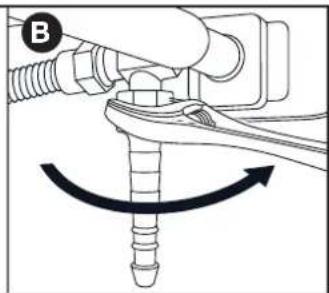
natural_image
Mechanical diagram showing a screw being inserted into a housing with an arrow indicating rotation (no text or symbols present)natural_image
Technical diagram of a mechanical assembly with a bolt and threaded component, showing an upward arrow (no text or symbols present)
text_image
D G6.3.2 Kupplung B
text_image
Technical diagram showing two mechanical assembly states (A and B) with labeled components and directional arrows indicating motion or force.text_image
Technical diagram showing two mechanical assembly steps labeled C and D, with arrows indicating direction of movement or adjustment.natural_image
Technical line drawing of a mechanical assembly with no visible text or symbols
natural_image
Line drawing of a mechanical device with no visible text or symbolsnatural_image
Line drawing of a toothbrush with 'barbecook' branding on the lid (no additional text or symbols)natural_image
Pure mechanical diagram showing a lever and pivot point without any text, numbers, or symbols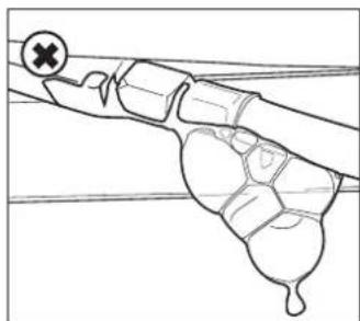
natural_image
Diagram of a hand holding a tool with a cross mark, no text or symbols presentnatural_image
Line drawing of a gas cylinder with labeled points A and directional arrows (no text or symbols on the object itself)
text_image
barbecook B
text_image
C barbe
text_image
D ! barbecook!natural_image
Technical line drawing of a mechanical component with an arrow indicating direction (no text or symbols)natural_image
Simple line drawing of a lever with two circular ends and a fulcrum (no text or symbols)natural_image
Technical line drawing of a mechanical component with an arrow indicating a process or assembly (no text or symbols present)natural_image
Line drawing of a toaster oven with a handle and cooling panel, showing no text or symbolsnatural_image
Diagram of a bottle with internal spiderweb structure and two butterflies (no text or labels)
natural_image
Technical line drawing of a mechanical assembly with three curved components and rotational arrows indicating motion (no text or symbols)natural_image
Technical line drawing of a mechanical device with two views: top shows a cylindrical component being inserted, bottom shows a flanged component with a handle (no text or symbols)natural_image
Technical line drawing of a mechanical component with three top views and a downward arrow indicating assembly or disassembly (no text or symbols present)4.3. Esmalte
natural_image
Technical line drawing of a portable grill with handlebars and control panel (no text or symbols)6.3.1. Manguito A
natural_image
Mechanical diagram showing a threaded fastener inserted into a pipe, with an upward arrow indicating force direction (no text or symbols present)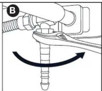
natural_image
Mechanical diagram showing a screw being inserted into a housing with an arrow indicating rotation (no text or symbols present)natural_image
Technical diagram of a mechanical assembly with a bolt and threaded pipe (no text or symbols)
text_image
D G6.3.2 Manguito B
natural_image
Diagram of a mechanical assembly with threaded pipe and valve, showing upward force indicator (no text or symbols)
natural_image
Mechanical diagram showing a lever mechanism with a curved arrow indicating rotational motion (no text or symbols present)text_image
Technical diagram showing mechanical assembly steps labeled C and D with directional arrows and cross symbolsnatural_image
Technical line drawing of a mechanical assembly with no visible text or symbols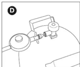
natural_image
Line drawing of a medical or laboratory setup with a device and tubing (no text or symbols)natural_image
Line drawing of a toothbrush with 'barbecook' text on the lid (no other text or symbols)7.5. Comprobar fugas de gas
natural_image
Pure mechanical diagram showing a lever and pivot point without any text, numbers, or symbols
natural_image
Diagram of a hand holding a small object with a cross mark, no text or symbols presentnatural_image
Line drawing of a gas cylinder with two arrows pointing to its side (no text or symbols)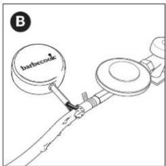
text_image
barbecook B
text_image
barbe C
text_image
D ! barbecook
natural_image
Diagram of a mechanical component with a shaft and housing, showing a directional arrow (no text or symbols)
natural_image
Simple line drawing of a mechanical lever or rod with two circular ends and a central dot (no text or symbols)natural_image
Technical line drawing of a mechanical device with internal compartments and a black arrow indicating a process (no text or symbols)natural_image
Line drawing of a portable stove interior with a fire extinguisher and a hand holding a tool (no text or symbols)natural_image
Diagram of a bottle with internal geometric patterns and two small insects (no text or symbols)
natural_image
Technical line drawing of a mechanical assembly with three curved components and rotational arrows indicating motion (no text or symbols)natural_image
Technical line drawing of a tool with a handle and base, showing two views (top: straight handle, bottom: circular base) with arrows indicating motion direction (no text or symbols)natural_image
Technical line drawing of a mechanical component with three top views and a downward arrow indicating process (no text or symbols)4.3. Smalto
natural_image
Technical line drawing of a portable grill with handlebars and control panel (no text or symbols)6.3.1. Raccordo A
natural_image
Mechanical diagram showing a threaded fastener inserted into a tank, with an upward arrow indicating force direction (no text or symbols present)
natural_image
Mechanical diagram showing a lever mechanism with a rotating shaft and nut, no text or symbols presentnatural_image
Technical diagram of a mechanical assembly with a threaded pipe and valve, showing an upward arrow (no text or symbols present)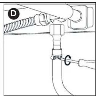
text_image
Diagram showing a pipe connection with labeled parts D and G, likely illustrating a mechanical or fluid system setup.6.3.2 Raccordo B
natural_image
Mechanical diagram showing a fastener or spring-loaded assembly with a curved arrow indicating rotational motion (no text or symbols present)natural_image
Mechanical assembly diagram showing a pipe fitting with a valve and directional arrow (no text or symbols)
natural_image
Mechanical diagram showing a lever mechanism with a valve and rotating component (no text or symbols)natural_image
Technical line drawing of a mechanical assembly with no visible text or symbols
natural_image
Line drawing of a mechanical device with a knob and lever (no text or symbols)natural_image
Line drawing of a toothbrush with 'barbecook' branding on the lid (no additional text or symbols)natural_image
Line drawing of a mechanical component with a checkmark indicating a detail (no text or symbols present)
natural_image
Diagram of a mechanical or biological structure with no visible text, numbers, or symbolsnatural_image
Line drawing of a gas cylinder with labeled section A and two arrows indicating flow direction (no text or symbols on the diagram itself)
text_image
B barbecook
natural_image
Technical diagram of a mechanical component with a tool inserted, showing a shaft and housing (no text or symbols)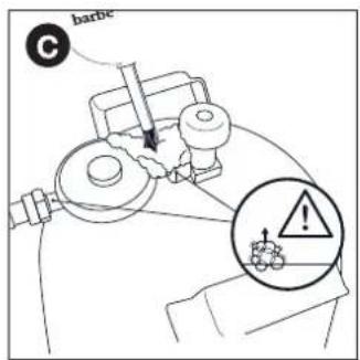
text_image
C barbc
text_image
D ! barbecook9. ACCENSIONE DEI BRUCIATORI
natural_image
Simple line drawing of a lever with two circular ends and a central dot (no text or symbols)natural_image
Technical line drawing of a vehicle chassis with internal compartments and a directional arrow indicating motion (no text or symbols)natural_image
Line drawing of a portable stove interior with a fire extinguisher being placed on top (no text or symbols)natural_image
Diagram of a bottle with spiderweb pattern and two butterflies (no text or symbols)
natural_image
Technical diagram of a mechanical assembly with three curved components and rotational arrows indicating motion (no text or symbols)natural_image
Technical line drawing of a mechanical device with two views: top shows a cylindrical component, bottom shows a circular base with a handle (no text or symbols)natural_image
Technical line drawing of a mechanical component with three top views and a downward arrow indicating assembly or disassembly (no text or symbols present)4.3. Esmalte
natural_image
Technical line drawing of a portable grill with handlebars and control panel (no text or symbols)natural_image
Technical diagram of a mechanical assembly with threaded components and an upward arrow indicator (no text or labels)
natural_image
Mechanical diagram showing a lever mechanism with a curved arrow indicating rotational motion (no text or symbols present)natural_image
Technical diagram of a mechanical assembly with a threaded pipe and connector (no text or symbols)
text_image
Technical diagram showing a pipe fitting with labeled components D and G, likely illustrating a mechanical or fluid system setup.6.3.2 Acoplamento B
natural_image
Mechanical diagram showing a lever mechanism with a curved arrow indicating rotational motion (no text or symbols present)natural_image
Mechanical assembly diagram showing a pipe fitting with a valve and directional arrow (no text or symbols)
natural_image
Mechanical diagram showing a valve assembly with rotating components (no text or symbols)natural_image
Technical line drawing of a mechanical assembly with no visible text or symbols
natural_image
Line drawing of a mechanical device with no visible text or symbolsnatural_image
Line drawing of a toothbrush with 'barbecook' branding on the lid (no additional text or symbols)natural_image
Pure mechanical diagram showing a lever and pivot point without any text, numbers, or symbols
natural_image
Diagram of a hand holding a small object with a cross symbol, no text or labels presentnatural_image
Line drawing of a gas cylinder with two arrows indicating direction (no text or symbols)
text_image
barbecock B
text_image
barbe C
text_image
D ! barbecook!
natural_image
Diagram of a mechanical component with a lever and directional arrow (no text or symbols)
natural_image
Simple line drawing of a lever with two circular ends and a fulcrum, no text or symbols present.natural_image
Line drawing of a mechanical device interior with internal compartments and a black arrow indicating a process or operation (no text or symbols present)natural_image
Line drawing of a portable stove interior with a fire extinguisher being inserted (no text or symbols)natural_image
Diagram of a bottle with internal geometric patterns and two butterflies (no text or symbols)
natural_image
Technical diagram of a mechanical assembly with three curved components and directional arrows indicating motion (no text or symbols)natural_image
Technical line drawing of a mechanical device with two views: top shows a cylindrical component with cable, bottom shows a flanged base with a handle (no text or symbols)natural_image
Technical line drawing of a mechanical component with three top views and a downward arrow indicating assembly or disassembly (no text or symbols present)4.3. Emailj
natural_image
Technical line drawing of a portable grill with handlebars and control panel (no text or symbols)6.3.1. Koppling A
natural_image
Technical diagram of a mechanical assembly with threaded components and an upward arrow indicator (no text or labels)
natural_image
Mechanical diagram showing a screw being inserted into a pipe fitting with an arrow indicating rotation (no text or symbols present)text_image
Technical diagram showing two installation steps of a pipe fitting with labeled components (C, D, G) and an upward arrow indicating direction.6.3.2 Koppling B
natural_image
Diagram of a mechanical assembly with threaded pipe and valve, showing upward force indicator (no text or labels)
natural_image
Mechanical diagram showing a lever mechanism with a curved arrow indicating rotational motion (no text or symbols present)natural_image
Mechanical assembly diagram showing a pipe fitting with a valve and directional arrow (no text or symbols)
natural_image
Mechanical diagram showing a valve assembly with a rotating knob and adjustment mechanism (no text or symbols)natural_image
Technical line drawing of a mechanical assembly with no visible text or symbols
natural_image
Line drawing of a mechanical device with no visible text or symbolsnatural_image
Line drawing of a decorative lamp with 'barbecook' text on the lid (no other text or symbols)natural_image
Pure mechanical diagram showing a lever and pivot point without any text, numbers, or symbols
natural_image
Diagram of a hand holding a small object with a cross mark, no text or symbols presentnatural_image
Line drawing of a gas cylinder with two arrows indicating flow direction (no text or symbols)
text_image
barbecook B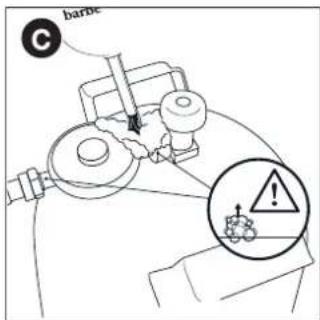
text_image
barne C
text_image
D ! barbecook
natural_image
Diagram of a mechanical tool or component with a pointed tip and arrow indicating direction (no text or symbols)
natural_image
Simple line drawing of a string with two circular ends and a dot at the end (no text or symbols)natural_image
Line drawing of a mechanical device interior with internal compartments and a black arrow indicating a directional change (no text or symbols)
natural_image
Line drawing of a toaster oven with a handle and cooling fan inside (no text or symbols)natural_image
Diagram of a bottle with internal spiderweb structure and two butterflies (no text or labels)
natural_image
Technical line drawing of a mechanical assembly with three curved components and rotational arrows indicating motion (no text or symbols)| Symbol Material | |
| ● | Enamel |
| ■ | Stainless steel |
| ★ | Powder coated |
[NL]
text_image
Exploded view diagram of a solar panel assembly with numbered components for identification| STELLA 3201BC-GAS-2036 | ||
| 1 BC-SPA-8979 | ● | |
| 2 BC-SPA-9021 | ● | |
| 3 BC-SPA-8938 | ||
| 4 BC-SPA-8995 | ||
| 5 BC-SPA-8984 | ||
| 6 BC-SPA-9370 | ■ | |
| 7 BC-SPA-9022 | ● | |
| 8 BC-SPA-9023 | ● | |
| 9 BC-SPA-9024 | ● | |
| 10 BC-SPA-9025 | ||
| 11 BC-SPA-9026 | ● | |
| 12 BC-SPA-9027 | ||
| 13 BC-SPA-8982 | ||
| 14 BC-SPA-9028 | ||
| 15 BC-SPA-9029 | ||
| 16 BC-SPA-9376 | ■ | |
| 17 BC-SPA-9030 | ■ | |
| 18 BC-SPA-9386 | ||
| 19 BC-SPA-9387 | ||
| 20 BC-SPA-9031 | ||
| 21 BC-SPA-9443 | ||
| STELLA 3201BC-GAS-2036 | ||
| 22 BC | -SPA-9439 | ★ |
| 23 BC | -SPA-9441 | ★ |
| 24 BC | -SPA-9006 | |
| 26 BC | -SPA-9007 | |
| 27 BC | -SPA-8994 | |
| 29 BC | -SPA-9449 | ★ |
| 30 BC | -SPA-9034 | ■★ |
| 31 BC | -SPA-9035 | ■ |
| 32 BC | -SPA-9407 | ★ |
| 33 BC | -SPA-9413 | ★ |
| 34 BC | -SPA-9005 | ★ |
| 35 BC | -SPA-9002 | ★ |
| 36 BC | -SPA-9003 | ★ |
| 37 BC | -SPA-9431 | |
| 38 BC | -SPA-9436 | |
| 39 BC | -SPA-8972 | |
| 40 BC | -SPA-8973 | |
| 41 BC | -SPA-9004 | ★ |
| 42 BC | -SPA-9008 | |
1
2

3

text_image
M X4 N X44
natural_image
Technical line drawing of a mechanical enclosure or enclosure with internal grating and mounting brackets (no text or symbols)5

natural_image
Technical line drawing of a metal enclosure with vertical supports and internal compartments (no text or symbols)6
1ST
natural_image
Technical line drawing of a mechanical device with no visible text or symbols
natural_image
Technical line drawing of a mechanical frame with two wheels and a 2nd-order panel (no text or symbols)

3RD

natural_image
Technical line drawing of a mechanical device with no visible text or symbols7

natural_image
Line drawing of a portable gas stove with control panel and wheels (no text or symbols)8

natural_image
Technical line drawing of a mechanical device with wheels and mounting bracket (no text or symbols)
text_image
9 A X4 E X4 H X4
natural_image
Technical line drawing of a wheeled cart with wheels and a labeled component 'A X2' (no text or symbols on the diagram itself)11

natural_image
Technical line drawing of a rectangular enclosure with internal components and a hanging arm, no text or symbols presentS X1
12

natural_image
Technical line drawing of a rectangular enclosure with internal components and ventilation ducts (no text or symbols)13

text_image
I J E X2 X2 X214

natural_image
Line drawing of a portable electric grill with wheels and control panel (no text or symbols)15

text_image
R X2 I X3 E X5 R I Dinamarack16

natural_image
Technical line drawing of a mechanical device with wheels and a handle, no text or symbols present17

natural_image
Line drawing of a 1st gas stove with wheels and control panel (no text or symbols)
natural_image
Technical line drawing of a mechanical device with no visible text or symbols18

natural_image
Technical line drawing of a mechanical device with open lid, central tray, and control panel (no text or symbols)M X2
M X1

natural_image
Technical line drawing of a mechanical device with open lid and internal components, showing mounting base and mounting bracket (no text or symbols)
natural_image
Circular diagram showing mechanical components with an upward arrow, no visible text or symbols19

text_image
AND + 1 - + + Not included AA battery LR 6, AM 3 1.5 V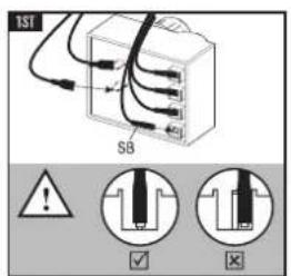
text_image
1ST SB
natural_image
Line drawing of a rectangular electronic device with a circular outline, showing wires and a knob (no text or symbols)20

natural_image
Technical line drawing of a mechanical device with wheels and a curved top component (no text or symbols)21

natural_image
Line drawing of a portable electric grill with open doors and wheels, showing internal components and a close-up inset (no text or symbols)22

natural_image
Line drawing of a standard electric grill with open chamber, wheels, and control panel (no text or symbols)23

natural_image
Line drawing of a portable electric grill with open top, grating tray, and wheels (no text or symbols)24

natural_image
Line drawing of a portable electric grill with control panel and wheels (no text or symbols)25

natural_image
Line drawing of a standard electric grill with open top, grating, and side-mounted tray (no text or symbols)26

natural_image
Line drawing of a standard outdoor grill with a curved top and side-mounted dish, mounted on a wheeled cart (no text or symbols)
natural_image
Technical line drawing of a portable gas stove or boiler unit with wheels and control panel (no text or symbols)| A | B | C | D | E | F | G | H | I | J | ||||||
| G30 | G31 | G30 | G31 | G30 | G31 | ||||||||||
| ®barbecook | Stella 3201BC-GAS-2036gas barbecue | LU - NL - DK - FI - SE - CY - CZ -EE - LT - MT - SK - SI - BG - IS - NOTR - HR - RO - IT - HU - LV | 28-30 mbar | propane,butane ortheir mixtures | I 3 B/P (30) | 1,5 Vbattery(not included) | 14.6 kW | 1062 g/h | 1043 g/h | 11.4 kW | 830 g/h | 815 g/h | 3.2 kW | 233 g/h | 229 g/h |
| BE - FR - IT - LU - IE - GR- PT - ES - CY - CZ - LT - SK - CHSI - LV | 28 30 mbar | butane | I 3 + (28-30/37) | 14.6 kW | 1062 g/h | 1043 g/h | 11.4 kW | 830 g/h | 815 g/h | 3.2 kW | 233 g/h | 229 g/h | |||
| 37 mbar | propane | ||||||||||||||

TYP STELLA 3201/5221 BBCH90805 A
Insulpter hoofdorander - Injecteur brûleur principale - Injector main burner - Injektor Hauptbrenner - Inlettoe bruciatore capo - Inyector para hornilla principal - Injector queimador principal - Inspruttingspumpen head gasbrännaren - Den store branders dysetype - Suutin pääpolittimen - Tryska hlavnich horäku - Tryska bočnych horäkov Type - Typ - Tipo - Typpi:0.991 (28-30-37 mbar) Insulpter zijbrander - Injecteur brûleur latérale - Injector side burner - Injektor Seitenkocher - Inlettoe bruciatore laterale - Inyector para hornilla lateral - Injector queimador lateral - Inspruttingspumpen side gasbrännaren - Side branders dysetype - Suutin svupolittimen - Tryska bočnih ohräku - Tryska bočnych horäkov - Type - Typ - Tipo - Typpi: 0.88 (28-30-37 mbar)
LIV WISE BARBECOOK® is a registered brand www.barbecook.com
LivWise Vaartlaan 9 9800 Deinze - Belgium info@livwise.be www.livwise.be
CE 2531/21 PIN: 2531CS-0076
Register your Barbecook® on www.barbecook.com and enjoy the full Barbecook® experience!

THIS IS YOUR UNIQUE SERIAL N°
FI - KÄYTTÖOPAS 4
DA-BRUGERVEJLEDNING14
NO - BRUKERVEILEDNING 24
IS - NOTENDAHANDBÓK 34
LV - LIETOŠANAS INSTRUKCIJA 44
SK – POUŽÍVATELŠKÁ PRÍRUČKA 54
LT – NAUDOTOJO VADOVAS 64
ET - KASUTUSJUHEND 74
FI – KÄYTTÖOPAS
1. REKISTERÖI LAITTEESI
natural_image
Technical line drawing of a mechanical device with two views: top shows a cylindrical component with a cable, bottom shows a circular component with a handle (no text or symbols)natural_image
Technical line drawing of a mechanical component with three top views and a downward arrow indicating assembly or disassembly (no text or symbols present)4.3. Emali
natural_image
Technical line drawing of a portable grill with handle and control panel (no text or symbols)6.3.1. Liitäntä A
natural_image
Mechanical diagram showing a threaded fastener inserted into a pipe with an upward arrow indicating force (no text or symbols present)
natural_image
Mechanical diagram showing a screw being inserted into a mechanical component with an arrow indicating rotation (no text or symbols present)text_image
Technical diagram showing two installation steps of a pipe fitting with labeled components (C, D, G) and an upward arrow indicating direction.6.3.2 Liitäntä B
natural_image
Mechanical diagram showing a fastener or spring-loaded assembly with a curved arrow indicating rotational motion (no text or symbols present)natural_image
Mechanical assembly diagram showing a valve or fitting with a directional arrow (no text or symbols present)
natural_image
Mechanical diagram showing a valve assembly with rotating components and a cross symbol (no text or labels)natural_image
Technical line drawing of a mechanical assembly with no visible text or symbols
natural_image
Line drawing of a mechanical device with no visible text or symbolsnatural_image
Line drawing of a toothbrush with 'barbecook' text on the head (no other text or symbols)natural_image
Pure technical line drawing of a mechanical component with no text or symbols
natural_image
Diagram of a hand holding a small object with a cross mark, no text or symbols presentnatural_image
Line drawing of a gas cylinder with two arrows indicating direction (no text or symbols)
text_image
barbecook B
text_image
baroc C
text_image
D ! barbecook!natural_image
Diagram of a mechanical component with a shaft and housing, showing a directional arrow (no text or symbols)natural_image
Simple line drawing of a mechanical lever with two circular components and a fulcrum (no text or symbols)natural_image
Technical line drawing of a mechanical component with internal compartments and a directional arrow indicating motion (no text or symbols)natural_image
Line drawing of a toaster oven with a handle and cooling fan inside (no text or symbols)natural_image
Diagram of a bottle with spiderweb and insect silhouettes inside, no text or symbols presentnatural_image
Technical line drawing of a mechanical assembly with three curved components and rotational arrows indicating motion (no text or symbols)natural_image
Technical line drawing of a mechanical device with two views: top shows a cylindrical component being inserted, bottom shows a flanged base with a handle (no text or symbols)natural_image
Technical line drawing of a mechanical component with three top views and a downward arrow indicating assembly or disassembly (no text or symbols present)4.3. Emalje
natural_image
Technical line drawing of a portable grill with handle and control panel (no text or symbols)6.3.1. Kobling A
natural_image
Mechanical diagram showing a threaded fastener inserted into a pipe with an upward arrow indicating force (no text or symbols present)
natural_image
Mechanical diagram showing a screw being inserted into a housing with an arrow indicating rotation (no text or symbols present)text_image
Technical diagram showing two installation steps of a pipe fitting with labeled components (C, D, G) and an upward arrow indicating direction.6.3.2 Kobling B
natural_image
Mechanical diagram showing a screw fastening assembly with rotational motion arrows (no text or labels)natural_image
Diagram of a mechanical assembly with a valve and threaded connector (no text or symbols)
natural_image
Mechanical diagram showing a valve assembly with rotating components and a cross symbol (no text or labels)6.4. Tilslut slangen og gasflasken til regulatoren.
natural_image
Technical line drawing of a mechanical assembly with no visible text or symbols
natural_image
Line drawing of a mechanical device with no visible text or symbolsnatural_image
Line drawing of a makeup brush with 'barbecook' text on the head (no other text or symbols)7.5. Kontrollere for gaslækager
natural_image
Pure mechanical diagram showing a lever and pivot point without any text, numbers, or symbols
natural_image
Diagram of a hand holding a tool with a cross mark and a droplet, no text or symbols presentnatural_image
Line drawing of a gas cylinder with two arrows indicating flow direction (no text or symbols)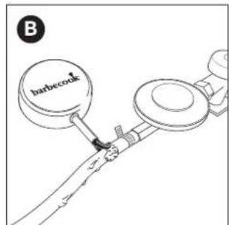
text_image
B barbecook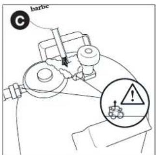
text_image
barbe C
text_image
D ! barbecook!
natural_image
Diagram of a mechanical component with a shaft and housing, showing a directional arrow (no text or symbols)
natural_image
Simple line drawing of a lever with two circular ends and a fulcrum, no text or symbols present.natural_image
Technical line drawing of a mechanical device interior with internal compartments and a directional arrow indicating motion (no text or symbols)
natural_image
Line drawing of a toaster oven with a handle and cooling fan inside (no text or symbols)natural_image
Diagram of a bottle with spiderweb structure inside, no text or symbols present
natural_image
Technical diagram of a mechanical assembly with three curved components and rotational arrows indicating motion (no text or symbols)natural_image
Technical line drawing of a mechanical device with two views: top shows a cylindrical component with cable, bottom shows a flanged base with a handle (no text or symbols)natural_image
Technical line drawing of a mechanical component with three top views and a downward arrow indicating process (no text or symbols)4.3. Emalje
natural_image
Technical line drawing of a portable grill with handle and control panel (no text or symbols)6.3.1. Kobling A
Du trenger en skrunøkkel (19 mm) og en stjerneskrutrekker.
natural_image
Mechanical diagram showing a screw being inserted into a component with an arrow indicating rotation (no text or symbols present)text_image
Technical diagram showing two configurations (C and D) of a pipe fitting with labeled components and an upward arrow indicating direction.6.3.2 Kobling B
natural_image
Mechanical diagram showing a fastener or screw assembly with rotational motion indicated by arrows (no text or symbols)- Skru gasslangen på koblingen (C) og fest den med to skrunøkler. Hold koblingen fast med en skrunøkkel (22 mm) og stram slangen med en justerbar skrunøkkel.

natural_image
Mechanical assembly diagram showing a valve and fitting with an upward arrow (no text or symbols)
natural_image
Mechanical diagram showing a lever mechanism with a cross symbol indicating rotational motion (no text or labels)6.4. Koble slangen og gassflasken til regulatoren.
natural_image
Technical line drawing of a mechanical assembly with no visible text or symbols
natural_image
Line drawing of a mechanical device with a cylindrical component and a handle (no text or symbols)- Hvis regulatoren har en gjeng, skrur du regulatoren mot
klokken på gassflasken (D)

Bruk kun regulatorer som tilfredsstiller EN 16129.
6.5. Bytt ut gassflasken
-
Lukk gassforsyningen og still alle betjeningstastene til OFF.
-
Koble fra den tomme gassflasken og koble til den fulle gassflasken.
-
Kontroller gassflasken, slangen og alle gassforbindelser for lekkasjer. Se «7. Se etter gasslekkasjer».

Vær oppmerksom på at du alltid må holde deg unna tennkilder när du bytter ut gassflasken.
natural_image
Line drawing of a toothpaste brush with 'barbecook' label on the head (no other text or symbols)natural_image
Pure mechanical diagram showing a lever and pivot point without any text, numbers, or symbols
natural_image
Simple line drawing of a hand holding a tool with a cross mark and a circular symbol (no text or labels)natural_image
Line drawing of a gas cylinder with two arrows indicating flow direction (no text or symbols)
text_image
B barbecock
text_image
barne C
text_image
D ! barbecook
natural_image
Technical diagram of a mechanical component with a shaft and housing, showing a directional arrow (no text or symbols)
natural_image
Simple line drawing of a lever with two circular ends and a fulcrum, no text or symbols present.natural_image
Line drawing of a vehicle interior showing a handle with a black arrow indicating direction (no text or symbols)
natural_image
Line drawing of a portable stove interior with a fire extinguisher being inserted (no text or symbols)11. VEDLIKEHOLD AV APPARATET
natural_image
Diagram of a bottle with spiderweb pattern inside, no text or symbols present
natural_image
Technical line drawing of a mechanical assembly with three curved components and rotational arrows indicating motion (no text or symbols)natural_image
Technical line drawing of a mechanical device with two views: top shows a cylindrical component with cable, bottom shows a flanged component with a handle (no text or symbols)natural_image
Technical line drawing of a mechanical component with three top views and a downward arrow indicating assembly or disassembly (no text or symbols present)4.3. Enamel
natural_image
Technical line drawing of a portable grill with handle and control panel (no text or symbols)6.3.1. Samtenging A
Pú parft 19 mm skiptilykil og Phillips skrúfjárn.
text_image
Technical diagram showing two mechanical assembly states (A and B) with labeled components and directional arrows indicating movement or force.text_image
Technical diagram showing two installation steps of a pipe fitting with labeled components (C, D, G) and an upward arrow indicating direction.6.3.2 Samtenging B
text_image
Technical diagram showing two mechanical assembly states labeled A and B, with arrows indicating direction of movement or force.text_image
Technical diagram showing two mechanical assembly states labeled C and D, with arrows indicating movement or force direction.natural_image
Technical line drawings of mechanical components (no text or symbols)- Ef prýstijafnarinn er með práð, skaltu skrúfa prýstijafnarann
rangsælis á gaskútinn (D)
⚠️ Notaðu einungis prýstijafnara sem uppfylla EN 16129.
6.5. Skipt um gaskút
natural_image
Line drawing of a toothbrush with 'barbecook' text on the head (no other text or symbols)natural_image
Pure mechanical diagram showing a lever and pivot point without any text, numbers, or symbols
natural_image
Simple line drawing of a hand holding a tool with a cross mark and a circular symbol (no text or labels)natural_image
Line drawing of a gas cylinder with two arrows indicating direction (no text or symbols)
text_image
barbecook B
text_image
barne C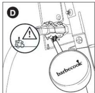
text_image
D !! barbecooknatural_image
Diagram of a mechanical component with a lever and directional arrow (no text or symbols)
9. KVEKJA Á BRENNURUNUM

natural_image
Simple line drawing of a lever with two circular ends and a fulcrum, no text or symbols present.natural_image
Line drawing of a mechanical component with a black arrow indicating a process or operation, no text or symbols present.
natural_image
Line drawing of a grater with a handle and cooling panel, showing a hand holding a tool near the lid (no text or symbols)natural_image
Diagram of a bottle with internal geometric patterns and two spines, no text or symbols present
natural_image
Technical line drawing of a mechanical assembly with three curved components and rotational arrows indicating motion (no text or symbols)natural_image
Technical line drawing of a mechanical device with two views: top shows a cylindrical component being inserted, bottom shows a flanged component with a handle (no text or symbols)natural_image
Technical line drawing of a mechanical component with three top views and a downward arrow indicating process (no text or symbols)4.3. Emalja
natural_image
Technical line drawing of a portable grill with control panel and mounting bracket (no text or symbols)6.3.1. Savienojums A
Jums ir nepieciešama 19 mm uzgriežnatslega un Phillips skrūvgriezis.
natural_image
Mechanical diagram showing a threaded fastener inserted into a pipe with an upward arrow indicating force (no text or symbols present)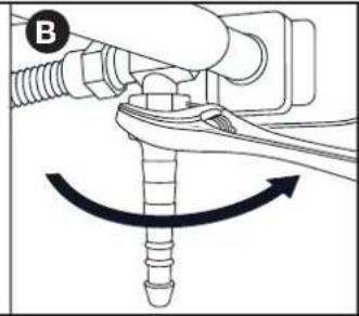
natural_image
Mechanical diagram showing a lever mechanism with a rotating screw and directional arrow (no text or symbols)natural_image
Technical diagram of a mechanical assembly with a threaded pipe and bolt, showing an upward force arrow (no text or symbols present)
text_image
D G6.3.2. Savienojums B
natural_image
Mechanical diagram showing a lever and nut assembly with rotational motion arrows (no text or symbols)natural_image
Mechanical assembly diagram showing a valve inserted into a fitting with a directional arrow indicating movement (no text or symbols present)
natural_image
Mechanical diagram showing a lever mechanism with a cross symbol indicating rotational motion (no text or labels)6.4. Savienojiet šlūteni un gāzes balonu ar regulatoru.
natural_image
Technical line drawing of a mechanical assembly with no visible text or symbols
natural_image
Line drawing of a mechanical device with no visible text or symbolsnatural_image
Line drawing of a toothbrush with 'barbecook' branding on the lid (no additional text or symbols)natural_image
Pure technical line drawing of a mechanical component with a circular detail and checkmark (no text or symbols)
natural_image
Line drawing of a hand holding a tool with a cross mark and droplet, no text or symbols presentnatural_image
Line drawing of a gas cylinder with two arrows indicating direction (no text or symbols)
text_image
B barbecock
text_image
barne C
text_image
D ! barbecook
natural_image
Diagram of a mechanical component with a lever and directional arrow (no text or symbols)
natural_image
Simple line drawing of a mechanical lever with two circular components and a fulcrum (no text or symbols)natural_image
Technical line drawing of a vehicle battery pack with an arrow indicating the direction (no text or symbols present)natural_image
Line drawing of a portable stove interior with a fire extinguisher being inserted (no text or symbols)natural_image
Diagram of a bottle with internal geometric patterns and two butterflies (no text or symbols)
natural_image
Technical line drawing of a mechanical assembly with three curved components and rotational arrows indicating motion (no text or symbols)natural_image
Technical line drawing of a mechanical device with two views: top shows a cylindrical component being inserted, bottom shows a circular component inserted into a housing (no text or symbols)natural_image
Technical line drawing of a mechanical component with three top views and a downward arrow indicating process (no text or symbols)4.3. Smalt
natural_image
Technical line drawing of a portable grill with handlebars and control panel (no text or symbols)6.3.1 Spojka A
natural_image
Technical diagram of a mechanical assembly with threaded components and an upward arrow indicator (no text or labels)
natural_image
Mechanical diagram showing a tool interacting with a screw and nut, with an arrow indicating rotation (no text or symbols present)natural_image
Technical diagram of a mechanical assembly with a threaded pipe and directional arrow (no text or symbols)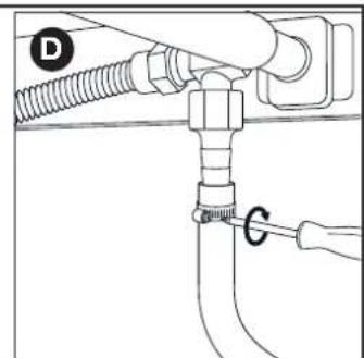
text_image
Technical diagram showing a pipe fitting with labeled components D and G, likely illustrating a valve or piping system.6.3.2 Spojka B
natural_image
Mechanical diagram showing a fastener or spring-loaded assembly with a curved arrow indicating rotational motion (no text or symbols present)natural_image
Diagram of a mechanical assembly with a valve and threaded connector (no text or symbols)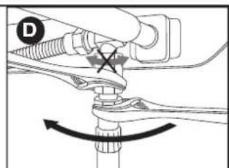
text_image
D6.4. Pripojte hadicu a plynovú fl'ašu k regulátoru.
natural_image
Technical line drawing of a mechanical assembly with no visible text or symbols
natural_image
Line drawing of a mechanical device with no visible text or symbolsnatural_image
Line drawing of a toothbrush with 'barbecook' branding on the head (no other text or symbols)natural_image
Line drawing of a mechanical component with a circular checkmark on the top (no text or symbols)
natural_image
Diagram of a hand holding a tool with a cross mark and droplet, no text or symbols presentnatural_image
Line drawing of a gas cylinder with two arrows indicating direction (no text or symbols)
text_image
barbecook B
text_image
barbe C
text_image
D ! barbecooknatural_image
Diagram of a mechanical component with a lever and shaft, showing directional movement (no text or symbols)
natural_image
Simple line drawing of a string with two circular ends and a dot at the end (no text or symbols)natural_image
Line drawing of a mechanical device interior with a black arrow indicating a component or operation (no text or symbols present)natural_image
Line drawing of a portable stove interior with a fire extinguisher being inserted (no text or symbols)natural_image
Diagram of a bottle with internal spiderweb structure and two insect-like figures (no text or labels)natural_image
Technical line drawing of a mechanical assembly with three curved components and rotational arrows indicating motion (no text or symbols)natural_image
Technical line drawing of a mechanical device with two views: top shows a cylindrical component being inserted, bottom shows a circular component with a handle (no text or symbols)natural_image
Technical line drawing of a mechanical component with three top views and a downward arrow indicating assembly or disassembly (no text or symbols present)4.3. Enamel
natural_image
Technical line drawing of a portable grill with handle and control panel (no text or symbols)6.3.1. A mova
natural_image
Technical diagram of a mechanical assembly with threaded components and an upward arrow indicator (no text or labels)
natural_image
Mechanical assembly diagram showing a pin inserted into a screw with a curved arrow indicating rotation (no text or symbols)text_image
Technical diagram showing pipe connection and cable installation steps labeled C, D, and G6.3.2 B mova
natural_image
Mechanical assembly diagram showing a fastener and spring-loaded connector (no text or symbols)natural_image
Diagram of a mechanical assembly with a threaded pipe and threaded fitting, showing an upward arrow (no text or symbols present)
text_image
Dnatural_image
Technical line drawing of a mechanical assembly with no visible text or symbols
natural_image
Line drawing of a mechanical device with no visible text or symbolsnatural_image
Line drawing of a toothpaste brush with 'barbecook' text on the head (no other text or symbols)natural_image
Technical line drawing of a mechanical component with a circular checkmark indicating a detail (no text or symbols present)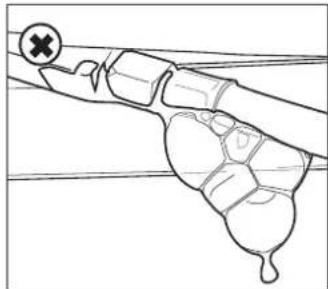
natural_image
Diagram of a hand holding a small object with a cross symbol, no text or labels presentnatural_image
Line drawing of a gas cylinder with two arrows pointing to its side (no text or symbols)
text_image
barbecook B
text_image
barbc C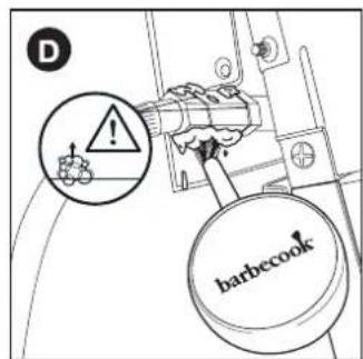
text_image
D ! barbecook
natural_image
Diagram of a mechanical component with a shaft and housing, showing a directional arrow (no text or symbols)
natural_image
Simple line drawing of a mechanical lever with two circular components and a fulcrum (no text or symbols)natural_image
Technical line drawing of a mechanical component with internal compartments and a directional arrow indicating motion (no text or symbols)natural_image
Line drawing of a portable stove interior with a fire extinguisher being inserted (no text or symbols)natural_image
Diagram of a bottle with spiderweb structure inside, showing internal patterns (no text or symbols)natural_image
Technical line drawing of a mechanical assembly with three curved components and rotational arrows indicating motion (no text or symbols)3. OLULISED OHUTUSJUHISED
natural_image
Technical line drawing of a mechanical device with two views: top shows a cylindrical component being inserted, bottom shows a flanged base with a handle (no text or symbols)natural_image
Technical line drawing of a mechanical component with three top views and a downward arrow indicating assembly or disassembly (no text or symbols present)4.3. Email
natural_image
Technical line drawing of a portable grill with handlebars and control panel (no text or symbols)6.3.1. A-ühendusotsik
natural_image
Technical diagram of a mechanical assembly with threaded components and an upward arrow indicator (no text or labels)
natural_image
Mechanical diagram showing a screw being inserted into a housing with an arrow indicating rotation (no text or symbols present)- Lükake voolik otsikule (C) ja pingutage klamber Phillipsi kruvikeerajaga (D) kinni.
text_image
Technical diagram showing two configurations (C and D) of a pipe fitting with labeled components and an upward arrow indicating direction.natural_image
Mechanical diagram showing a lever mechanism with a spring and nut, no text or symbols presentnatural_image
Diagram of a mechanical assembly with a valve and threaded connector (no text or symbols)
natural_image
Mechanical diagram showing a valve assembly with a rotating arrow indicating motion (no text or symbols)natural_image
Technical line drawing of a mechanical assembly with no visible text or symbols
natural_image
Line drawing of a mechanical device with a handle and lever (no text or symbols)natural_image
Line drawing of a toothbrush with 'barbecook' text on the head (no other text or symbols)natural_image
Pure mechanical diagram showing a lever and pivot (no text or symbols)
natural_image
Line drawing of a hand gripping a small object with a cross symbol (no text or labels)natural_image
Line drawing of a gas cylinder with two arrows indicating direction (no text or symbols)
text_image
barbecook B
text_image
barbe C
text_image
D ! barbecook
natural_image
Diagram of a mechanical component with a shaft and housing, showing a directional arrow (no text or symbols)
natural_image
Simple line drawing of a mechanical lever with two circular components and a fulcrum (no text or symbols)natural_image
Technical line drawing of a mechanical device with internal compartments and a handle, showing no text or symbolsnatural_image
Line drawing of a kitchen appliance with a handle and a pan, showing a lever mechanism (no text or symbols)natural_image
Diagram of a bottle with spiderweb pattern inside, no text or symbols presentnatural_image
Technical line drawing of a mechanical assembly with three curved components and rotational arrows indicating motion (no text or symbols)| Symbol Material | |
| ● | Enamel |
| ■ | Stainless steel |
| ★ | Powder coated |
[NL]
text_image
Exploded view diagram of a solar panel assembly with numbered components for identification and assembly reference.| STELLA 3201BC-GAS-2036 | |
| 1 BC-SPA-8979 | ● |
| 2 BC-SPA-9021 | ● |
| 3 BC-SPA-8938 | |
| 4 BC-SPA-8995 | |
| 5 BC-SPA-8984 | |
| 6 BC-SPA-9370 | ■ |
| 7 BC-SPA-9022 | ● |
| 8 BC-SPA-9023 | ● |
| 9 BC-SPA-9024 | ● |
| 10 BC-SPA-9025 | |
| 11 BC-SPA-9026 | ● |
| 12 BC-SPA-9027 | |
| 13 BC-SPA-8982 | |
| 14 BC-SPA-9028 | |
| 15 BC-SPA-9029 | |
| 16 BC-SPA-9376 | ■ |
| 17 BC-SPA-9030 | ■ |
| 18 BC-SPA-9386 | |
| 19 BC-SPA-9387 | |
| 20 BC-SPA-9031 | |
| 21 BC-SPA-9443 | |
| STELLA 3201BC-GAS-2036 | ||
| 22 BC-SPA-9439 | ★ | |
| 23 BC-SPA-9441 | ★ | |
| 24 BC-SPA-9006 | ||
| 26 BC-SPA-9007 | ||
| 27 BC-SPA-8994 | ||
| 29 BC-SPA-9449 | ★ | |
| 30 BC-SPA-9034 | ■★ | |
| 31 BC-SPA-9035 | ■ | |
| 32 BC-SPA-9407 | ★ | |
| 33 BC-SPA-9413 | ★ | |
| 34 BC-SPA-9005 | ★ | |
| 35 BC-SPA-9002 | ★ | |
| 36 BC-SPA-9003 | ★ | |
| 37 BC-SPA-9431 | ||
| 38 BC-SPA-9436 | ||
| 39 BC-SPA-8972 | ||
| 40 BC-SPA-8973 | ||
| 41 BC-SPA-9004 | ★ | |
| 42 BC-SPA-9008 | ||
1

2

3
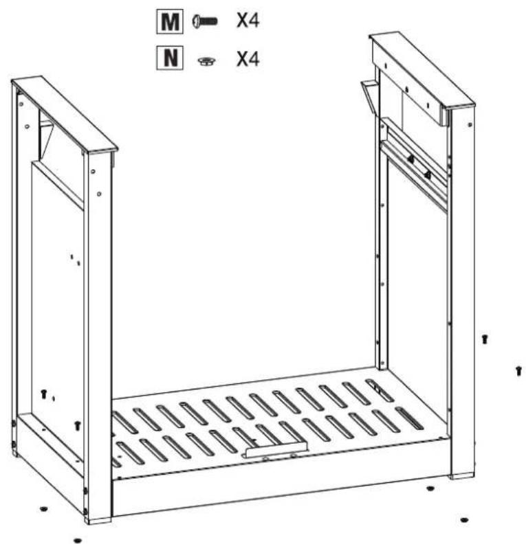
text_image
M X4 N X44

natural_image
Technical line drawing of a mechanical enclosure or enclosure with internal grating and mounting brackets (no text or symbols)5

natural_image
Technical line drawing of a metal enclosure with vertical supports and internal compartments (no text or symbols)6
1ST

natural_image
Technical line drawing of a mechanical device with no visible text or symbols
natural_image
Technical line drawing of a mechanical frame with two wheels and a 2nd-order panel (no text or symbols)

3RD
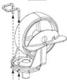
natural_image
Technical line drawing of a mechanical device with no visible text or symbols7

natural_image
Line drawing of a portable gas stove with control panel and wheels (no text or symbols)8

natural_image
Technical line drawing of a mechanical device with wheels and mounting bracket (no text or symbols)
text_image
9 A X4 E X4 H X4
natural_image
Technical line drawing of a wheeled cart with wheels and a labeled component 'A X2' (no text or symbols on the diagram itself)11
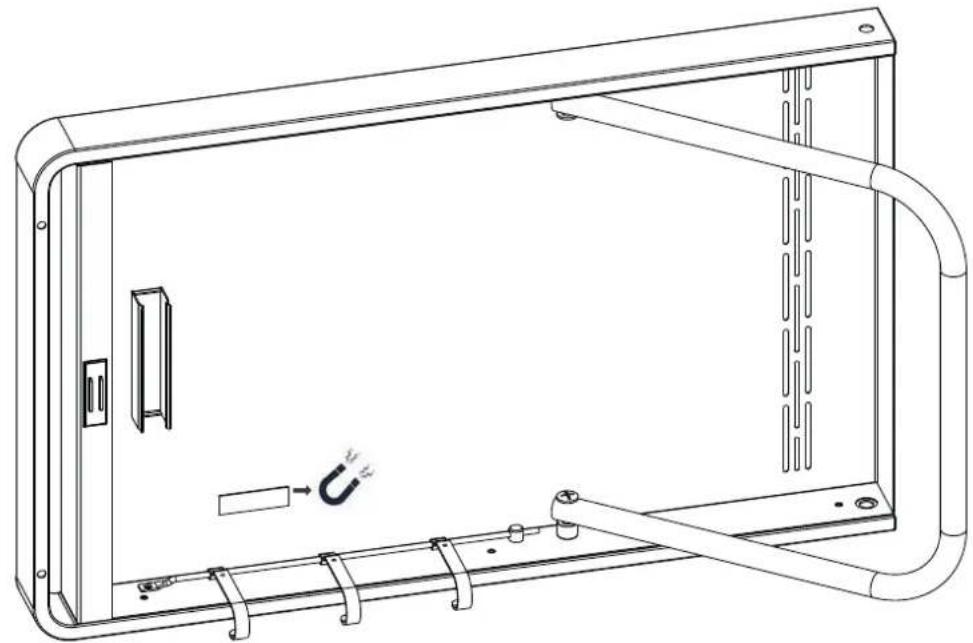
natural_image
Technical line drawing of a rectangular enclosure with internal components and a hanging arm, no text or symbols presentS X1
12

natural_image
Technical line drawing of a rectangular enclosure with internal components and a curved pipe (no text or symbols)13

text_image
I J E X2 X2 X214

natural_image
Line drawing of a portable electric grill with wheels and control panel (no text or symbols)15

text_image
R X2 I X3 E X5 R I R I R16

natural_image
Technical line drawing of a mechanical device with wheels and a handle, no text or symbols present17

natural_image
Line drawing of a 1st gas stove with wheels and control panel (no text or symbols)
natural_image
Technical line drawing of a mechanical device with no visible text or symbols18

natural_image
Technical line drawing of a mechanical device with open lid, central tray, and control panel (no text or symbols)M X2
M X1

natural_image
Technical line drawing of a mechanical device with open lid and internal components, showing exploded view (no text or symbols)
natural_image
Circular diagram showing mechanical components with an upward arrow, no visible text or symbols19

text_image
AND + 1 - + + Not included AA battery LR 6, AM 3 1.5 V
text_image
1ST SB
natural_image
Line drawing of a rectangular electronic device with a circular outline, showing wires and a knob (no text or symbols)20

natural_image
Technical line drawing of a mechanical device with wheels and a curved top component (no text or symbols)21

natural_image
Line drawing of a portable electric grill with open doors and wheels, showing internal components and a close-up inset (no text or symbols)22

natural_image
Line drawing of a standard electric grill with open chamber, wheels, and control panel (no text or symbols)23

natural_image
Line drawing of a portable electric grill with open top, grating tray, and wheels (no text or symbols)24
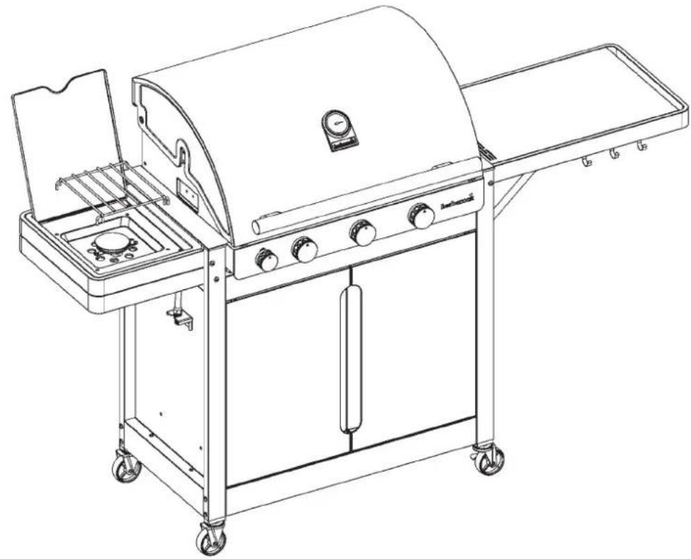
natural_image
Line drawing of a portable electric grill with control panel and wheels (no text or symbols)25

natural_image
Line drawing of a standard electric grill with open top, grating, and side-mounted tray (no text or symbols)26
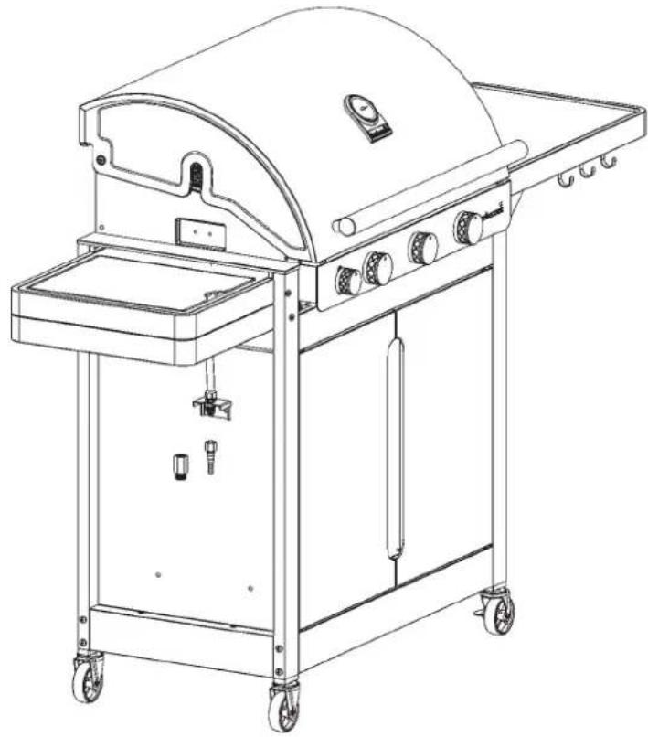
natural_image
Line drawing of a standard outdoor grill with a curved top and side-mounted dish, mounted on a wheeled cart (no text or symbols)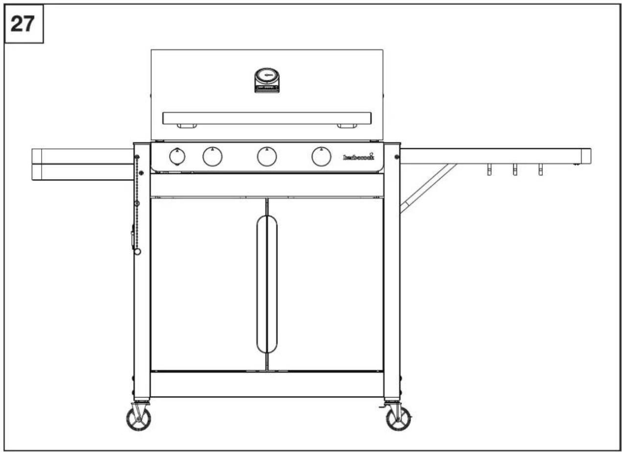
natural_image
Technical line drawing of a portable gas stove or boiler unit with wheels and control panel (no text or symbols)| A | B | C | D | E | F | G | H | I | J | ||||||
| G30 | G31 | G30 | G31 | G30 | G31 | ||||||||||
| ®barbecook®Stella 3201BC-GAS-2036gas barbecue | LU - NL - DK - FI - SE - CY - CZ -EE - LT - MT - SK - SI - BG - IS - NOTR - HR - RO - IT - HU - LV | 28-30 mbar | propane,butane ortheir mixtures | I 3 B/P (30) | 1,5 Vbattery(not included) | 14.6 kW | 1062 g/h | 1043 g/h | 11.4 kW | 830 g/h | 815 g/h | 3.2 kW | 233 g/h | 229 g/h | |
| BE - FR - IT - LU - IE - GR- PT - ES - CY - CZ - LT - SK - CHSI - LV | 28-30 mbar | butane | I 3 + (28-30/37) | 14.6 kW | 1062 g/h | 1043 g/h | 11.4 kW | 830 g/h | 815 g/h | 3.2 kW | 233 g/h | 229 g/h | |||
| 37 mbar | propane | ||||||||||||||

TYP STELLA 3201/5221 BBCH90805 A
Insulter hoofdorander - Injecteur brûleur principale - Injector main burner - Injektor Hauptbrenner - Inlettoe bruciatore capo - Inyector para hornilla principal - Injector queimador principal - Inspruttingspumpen head gasbrännaren - Den store branders dysetype - Suutin pääpolittimen - Tryska hlavnich horäku - Tryska bočnych horäkov Type - Typ - Tipo - Typpi:0.991 (28-30-37 mbar) Insulter zijbrander - Injecteur brûleur latérale - Injector side burner - Injektor Seitenkocher - Inlettoe bruciatore laterale - Inyector para hornilla lateral - Injector queimador lateral - Inspruttingspumpen side gasbrännaren - Side branders dysetype - Suutin svupolittimen - Tryska bočnice horäku - Tryska bočnych horäkov - Type - Typ - Tipo - Typpi: 0.88 (28-30-37 mbar)
LIV WISE BARBECOOK® is a registered brand www.barbecook.com
LivWise Vaartlaan 9 9800 Deinze - Belgium info@livwise.be www.livwise.be
CE 2531/21 PIN: 2531CS-0076
Register your Barbecook® on www.barbecook.com and enjoy the full Barbecook® experience!

THIS IS YOUR UNIQUE SERIAL N°
HR - KORISNIČKI PRIRUČNIK 4
SL - UPORABNIŠKI PRIROČNIK 14
CS - UŽIVATELSKÁ PŘÍRUČKA 24
MT - GWIDA GHALL-UTENT 34
3. VAŽNE SIGURNOSNE UPUTE
natural_image
Technical line drawing of a mechanical device with two views: top shows a flat cylindrical component, bottom shows a circular component with a handle and mounting bracket (no text or symbols)natural_image
Technical line drawing of a mechanical component with three top views and a downward arrow indicating assembly or disassembly (no text or symbols present)4.3. Emajl
natural_image
Technical line drawing of a portable grill with handlebars and control panel (no text or symbols)6.3.1. Spojnica A
Potreban vam je ključ od 19 mm i odvijač Phillips.
- pričvrstite spojnicu na plinsko crijevo na proizvodu (A) i zategnite ključem od 19 mm (B).

natural_image
Mechanical diagram showing a threaded fastener inserted into a pipe with an upward arrow indicating force (no text or symbols present)
natural_image
Mechanical diagram showing a screw being inserted into a housing with an arrow indicating rotation (no text or symbols present)- prebacite crijevo preko spojnice (C) i zategnite steznu
obujmicu odvijačem Phillips (D).
SAVJET: nanesite malu količinu sapuna za posuđe na spojnicu i zagrijte kraj crijeva za plin sušilom za kosu tako da glatko klizi preko spojnice.

text_image
Technical diagram showing two installation steps of a pipe fitting with labeled components (C, D, G) and an upward arrow indicating direction.6.3.2 Spojnica B
Potreban vam je ključ od 22 mm i podesivi ključ.
- pričvrstite spojnicu na plinsko crijevo na proizvodu (A) i zategnite ključem od 22 mm (B).

natural_image
Diagram of a mechanical assembly with threaded pipe and valve, showing upward force indicator (no text or labels)
natural_image
Mechanical diagram showing a fastener or spring-loaded assembly with a curved arrow indicating rotational motion (no text or symbols present)- pričvrstite plinsko crijevo na spojnicu (C) i učvrstite s pomoću dva ključa. Čvrsto držite spojnicu jednim ključem od 22 mm i zategnite crijevo podesivim ključem.

natural_image
Mechanical assembly diagram showing a pipe fitting with a valve and directional arrow (no text or symbols)
natural_image
Mechanical diagram showing a valve assembly with rotating components and a cross symbol (no text or labels)6.4. Spojite crijevo i plinsku bocu na regulator.
Trebat će vam odvijač Phillips i/ili podesivi ključ, ovisno o vrsti regulatora koji upotrebljavate.
natural_image
Technical line drawing of a mechanical assembly with no visible text or symbols
natural_image
Line drawing of a mechanical device with no visible text or symbols- Ako regulator tlaka ima navoj, pričvrstite regulator tlaka na plinsku bocu okretanjem u smjeru suprotnom od kretanja kazaljki na satu (D).
Koristite samo regulatore tlaka koji zadovoljavaju odredbe norme EN 16129.
6.5. Zamjena plinske boce
natural_image
Line drawing of a toothbrush with 'barbecook' text on the head (no other text or symbols)natural_image
Pure mechanical diagram showing a lever and pivot point without any text, numbers, or symbols
natural_image
Simple line drawing of a hand holding a tool with a cross mark and a circular symbol (no text or labels)natural_image
Line drawing of a gas cylinder with two arrows pointing to its side (no text or symbols)
text_image
barbecook B
text_image
barbe C
text_image
D ! barbecooknatural_image
Diagram of a mechanical tool or component with a cylindrical shaft and a pointed tip, showing directional movement (no text or symbols)
natural_image
Simple line drawing of a mechanical lever with two circular components and a fulcrum (no text or symbols)- otvorite poklopac i postavite sve regulatore glavnih plamenika na OFF.
- ako još niti jedan plamenik nije upaljen, otvorite dovod plina i pričekajte deset sekundi da se plin stabilizira.
- zapalite šibicu i držite oko 13 mm udaljenu od plamenika.

natural_image
Line drawing of a mechanical device interior with a black arrow indicating a process or operation (no text or symbols present)- postavite regulator plamena za jedan plamenik na VISOKO.

natural_image
Line drawing of a toaster oven with a handle and cooling grille (no text or symbols)natural_image
Diagram of a bottle with internal spiderweb pattern and two insect-like figures (no text or symbols)
Oštećenja nastala kao rezultat začepljenih plamenika i venturijeve cijevi smatraju se lošim održavanjem i nisu pokrivena jamstvom.
11.3.2 Kada treba očistiti plamenike i venturijeve cijevi?
natural_image
Technical line drawing of a mechanical assembly with three curved components and rotational arrows indicating motion (no text or symbols)natural_image
Technical line drawing of a mechanical device with two views: top shows a cylindrical component being inserted, bottom shows a flanged component with a handle (no text or symbols)natural_image
Technical line drawing of a mechanical component with three top views and a downward arrow indicating assembly or disassembly (no text or symbols present)4.3. Emajl
natural_image
Technical line drawing of a portable grill with control panel and tray (no text or symbols)6.3.1. Spojka A
text_image
Technical diagram showing two mechanical assembly states labeled A and B, with arrows indicating direction of movement or force.- Cev potisnite skozi spojko (C) in objemko za cev zategnite s križnim izvijačem (D).
NAMIG: Na spojko nanesite majhno količino mila za posodo, konec plinske cevi pa segrejte s sušilcem za lase, da gladko zdrsi skozi spojko.
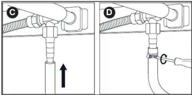
text_image
Technical diagram showing two installation steps of a pipe fitting with labeled components (C, D, G) and an upward arrow indicating direction.6.3.2 Spojka B
Potrebujete ključ širine 22 mm in nastavljiv ključ.
- Spojko privijte na plinsko cev na napravi (A) in jo zategnite s ključem širine 22 mm (B).

text_image
Technical diagram showing two mechanical assembly states labeled A and B, with arrows indicating direction of movement or force.- Plinsko cev privijte na spojko (C) in jo pritrdite z obema ključema. Spojko čvrsto držite s ključem širine 22 mm, cev pa zategnite z nastavljivim ključem.
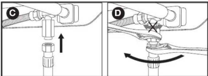
text_image
Technical diagram showing mechanical assembly with labeled parts C and D, including directional arrows and a cross symbol indicating a specific component.6.4. Priključitev cev in plinsko jeklenko na regulator.
natural_image
Technical line drawings of mechanical components (no text or symbols)- Če ima regulator navojno glavo, ga privijte na plinsko jeklenko v nasprotni smeri urnega kazalca (D).
natural_image
Line drawing of a decorative lamp with 'barbecook' text on its body (no other text or symbols)7.5. Preverjanje uhajanja plina
natural_image
Pure mechanical diagram showing a lever mechanism with a circular indicator (no text or symbols)
natural_image
Simple line drawing of a hand holding a tool with a cross mark and a circular symbol (no text or labels)natural_image
Line drawing of a gas cylinder with two arrows pointing to its side (no text or symbols)
text_image
barbecook B
text_image
barbe C
text_image
D ! barbecook!natural_image
Diagram of a mechanical component with a shaft and housing, showing a directional arrow (no text or symbols)
natural_image
Simple line drawing of a lever with two circular ends and a fulcrum (no text or symbols)natural_image
Line drawing of a mechanical component with internal compartments and a black arrow indicating a process or movement (no text or symbols)
natural_image
Line drawing of a kitchen appliance with a handle and internal grating (no text or symbols)natural_image
Diagram of a bottle with spiderweb pattern and two butterflies (no text or symbols)
natural_image
Technical line drawing of a mechanical assembly with three curved components and rotational arrows indicating motion (no text or symbols)natural_image
Technical line drawing of a mechanical device with two views: top shows a cylindrical component being inserted, bottom shows a circular component with a handle (no text or symbols)natural_image
Technical line drawing of a mechanical component with three top views and a downward arrow indicating assembly or disassembly (no text or symbols present)4.3. Smalt
natural_image
Technical line drawing of a portable grill with handle and control panel (no text or symbols)6.3.1. Spojka A
natural_image
Mechanical diagram showing a threaded fastener inserted into a pipe with an upward arrow indicating force (no text or symbols present)
natural_image
Mechanical assembly diagram showing a screw being inserted into a housing with a curved arrow indicating rotation (no text or symbols)text_image
Technical diagram showing two installation steps of a pipe fitting with labeled components (C, D, G) and an upward arrow indicating direction.6.3.2 Spojka B
natural_image
Mechanical diagram showing a fastener or clamp assembly with rotational motion indicated by arrows (no text or symbols)natural_image
Mechanical assembly diagram showing a valve and fitting with an upward arrow (no text or symbols)
natural_image
Mechanical diagram showing a valve assembly with rotating components and a cross symbol (no text or labels)natural_image
Technical line drawing of a mechanical assembly with no visible text or symbols
natural_image
Line drawing of a mechanical device with no visible text or symbolsnatural_image
Line drawing of a toothbrush with 'barbecook' text on the head (no other text or symbols)natural_image
Pure mechanical diagram showing a lever mechanism with a circular head and guide (no text or symbols)
natural_image
Simple line drawing of a hand holding a tool with a cross mark and a circle on the handle (no text or symbols)natural_image
Line drawing of a gas cylinder with two arrows indicating direction (no text or symbols)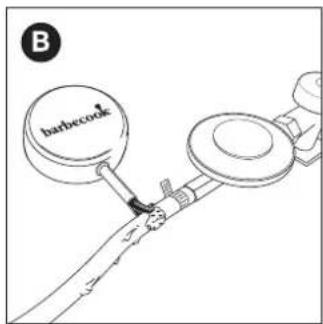
text_image
B barbecue
text_image
barbe C
text_image
D harbecook!
natural_image
Diagram of a mechanical tool or component with a pointed tip and arrow indicating direction (no text or symbols)
natural_image
Simple line drawing of a mechanical lever with two circular components and a fulcrum (no text or symbols)natural_image
Line drawing of a vehicle interior showing a mechanical component with an arrow indicating direction (no text or symbols present)natural_image
Line drawing of a toaster oven with a handle and cooling fan inside (no text or symbols)natural_image
Diagram of a bottle with internal geometric patterns and two spider-like figures inside (no text or symbols)
natural_image
Technical line drawing of a mechanical assembly with three curved components and rotational arrows indicating motion (no text or symbols)MT - GWIDA GHALL-UTENT
1. IRREGISTRA L-APPARAT TIEGHEK
natural_image
Technical line drawing of a mechanical device with two views: top shows a cylindrical component being inserted, bottom shows a flanged component with a handle (no text or symbols)Il-gass jghaddi mit-tubi venturi fi triqtu lejn il-burners. Il-gass jithallat mal-arja (u, ghalhekk, l-ossigenu) mill-fethiet fil-gnub. Dan hu essenzjali ghal kombustjoni xierqa fil-burners: kombustjoni xierqa tehtieg it-tahlita korretta ta' gass / ossignu biex taghti fjammi sbieh.
4.2. Ghotjien tal-burners
L-ghotjien tal-burners huma ghotjien imwahhla fuq il-burners fuq il-barbecue. Dawn jipprotegu l-burners mit-taqtir tax-xaham u ghandhom rwol krućjali fl-užu tal-barbecue. Il-fethiet mghottija fuq il-ğnub tal-ghotjien iqassmu s-shana fuq il-gradilja sabiex tishon aktar malajr u b'mod aktar uniformi.
Oqghod attent b'mod partikolari ghall-ghotjien tal-burners meta tkun qed tarma l-barbecue. Id-distribuzzjoni tas-shana tkun l-ahjar meta kull ghatu jitwahhal fuq il-burner it-tajjeb.

natural_image
Technical line drawing of a mechanical component with three top views and a downward arrow indicating assembly or disassembly (no text or symbols present)4.3. Enemel
Xi partijiet tal-apparat huma mghottija f'saff ta' hgieğ imdewweb, maghruf ukoll bhala enemel. Dan l-enemel jipproteği l-metall ta'taht mill-korrużjoni. L-enemel huwa materjal ta' kwalità gholja: huwa rezistenti ghall-korrużjoni, ma jiddegradax taht l-influwenza ta' temperaturi gholjin u huwa facli hafna biex jinghata manutenzjoni.

Peress li l-enemel huwa inqas flessibbli mill-metall li jinsab imwahhal fuqu, bicciet tal-enemel jistghu jinqalghu meta l-apparat jintuza hazin. Biex tevita din il-problema, trid toqghod attent meta tarma l-partijiet tal-enemel u dejjem trid tiehu hsieb l-enemel skont l-istruzzjonijiet f'dan il-manwal.
4.4. Flare-ups
Flare-ups huma fjammi li jitilghu ghall-gharrieda mir-recipient meta tkun qed tiggrilja. Generalment dawn ikunu kkawzati mit-taqtir tax-xaham jew l-immarinar.
5. L-IMMUNTAR TAL-APPARAT
natural_image
Technical line drawing of a portable grill with handlebars and internal components (no text or symbols)6.3.1. Coupling A
Ghandek bżonn spanner ta' 19-il mm u tornavit Phillips.
natural_image
Mechanical diagram showing a threaded fastener inserted into a pipe with an upward arrow indicating force (no text or symbols present)
natural_image
Mechanical diagram showing a screw being inserted into a valve with a curved arrow indicating rotation (no text or symbols present)- Žeržaq il-pajp fuq il-coupling (C) u ssikka l-holqa tal- ikklampjar b'tornavit Phillips (D).
PARIR: Applika ammont żghir ta' sapun tal-platti fuq il-coupling u sañhan it-tarf tal-pajp tal-gass b'nixxief tax-xaghar (hair drier) sabiex jiżzerząq bla xkiel fuq il-coupling.

text_image
Technical diagram showing two installation steps of a pipe fitting with labeled components (C, D, G) and an upward arrow indicating direction.6.3.2 Coupling B
Ghandek bżonn spanner ta' 22 mm u spanner agğustabbli.
natural_image
Diagram of a mechanical assembly with threaded pipe and valve, showing upward force indicator (no text or labels)
natural_image
Mechanical diagram showing a lever mechanism with a curved arrow indicating rotational motion (no text or symbols present)- Invita I-pajp tal-gass fuq il-coupling (C) u ssikkah b'żewg spanners. Żomm il-coupling sew bi spanner ta' 22 mm u ssikka I-pajp bi spanner agğustabbli.

natural_image
Mechanical assembly diagram showing a pipe fitting with a valve and directional arrow (no text or symbols)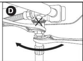
text_image
D6.4. Qabbad il-pajp u c-čilindru tal-gass mar-regolatur.
Se jkollok bżonn tornavit Phillips u/jew spanner agğustabbli skond it-tip ta' regolatur li qed tuża.
- Qabbad il-pajp mar-regolatur tal-pressjoni. Ipprocedi kif gej:
- Jekk il-pajp huwa mghammar b'holqa tal-ikklampjar, żerżaq il-pajp fuq ir-regolatur u ssikka l-holqa tal-ikklampjar b'tornavit Phillips (A).
- Jekk il-pajp ikun mghammar bi skorfina, invita l-pajp fuq irregolatur u ssikka l-iskorfina bi spanner aggustabbli (B).
- Qabbad ir-regolatur tal-pressjoni mać-čilindru tal-gass. Ipprocedi kif ğej:
- Jekk ir-regolatur huwa mghammar bi skorfina, invita r-regolatur fuq ic-čilindru tal-gass lejn il-lemin u ssikka l-iskorfina bi spanner ağğustabbli (C).

natural_image
Technical line drawing of a mechanical assembly with no visible text or symbols
natural_image
Line drawing of a mechanical device with no visible text or symbols- Jekk ir-regolatur ghandu kamin, invita r-regolatur fuq icčilindru tal-gass lejn ix-xellug (D)

Uza biss regolaturi li jissodisfaw I-EN 16129.
6.5. Ibdel ic-čilindru tal-gass
-
Aghlaq il-provvista tal-gass u poggi l-pumi tal-kontroll kollha fug OFF.
-
Skonnettja c-čilindru tal-gass il-vojt u qabbad ic-čilindru tal-gass il-mimli.
-
Iččekkja č-čilindru tal-gass, il-pajp, u l-konnessjonijiet kollha tal-gass ghall-hruğ tal-gass. Ara "7. Kif tiččekja ghall-hruğ tal-gass".

Innota li meta tibdel ic-čilindru tal-gass, ghandek dejjem tkun 'il boghod sew minn sorsi ta' tqabbid.
7. KIF TIČČEKJA GHALL-HRUĞ TAL-GASS
7.1. Ghaliex ghandek tiččekkja ghall-hruğ tal-gass?
Il-propan u l-butan huma t-tnejn itqal mill-arja. Dan ifisser li dawn il-gassijiet ma jitbieghdux jekk joñorgu mill-apparat. Fil-granet bla rih, il-gass li jkun hareğ jista' jakkumula ğewwa u madwar l-apparat u sussegwentement jiehu n-nar u jisplodi.
7.2. Meta ghandek tiččekkja ghall-hruğ tal-gass?
- Qabel l-ewwel użu jew wara perjodu twil fejn l-apparat ma kienx qed jintuża.

Icčekkja li m'hemmx hruğ ta' gass jekk l-apparat ğie mmuntat mill-fornitur.
- Ghandek taghmel dan kull meta tibdel parti tal-gass.
- Mill-ingas darba fis-sena, idealment fil-bidu tal-istagun.
natural_image
Line drawing of a toothbrush with 'barbecook' label on the head (no other text or symbols)7.5. Iččekkja ghall-hruğ tal-gass
natural_image
Pure mechanical diagram showing a lever and pivot point without any text, numbers, or symbols
natural_image
Simple line drawing of a hand holding a tool with a cross mark and a circular symbol (no text or labels)Ipprocedi kif ğej biex tivverifika l-ħruġ tal-gass:
-
Poğgi I-apparat barra.
-
Hu l-ghodda ghall-ittestjar tal-hrug tal-gass u l-fluwidu tat-test (sprej apposta jew tahlita ta' ilma/sapun tal-platti)
-
Iftah l-ghatu u poggi l-pumi tal-kontroll kollha fuq OFF.
-
Iftah il-provvista tal-gass ftit. Biex taghmel dan, dawwar il-valv fuq il-provvista tal-gass darba biss.
-
Igbed ammont żghir ta' fluwidu tat-test bl-ghodda għall- ittestjar tal-ħruġ tal-gass u applikah maż-żona li trid tiċċekkja. Il-partijiet li ğejjin għandhom jigu ĉċekkjati:
• Il-gonot tal-welding fuq ic-čilindru tal-gass (A)
• Il-pajp (B)
- Il-konnessjonijiet bejn ic-cilindru tal-gass u r-regolatur tal-pressjoni u bejn ir-regolatur tal-pressjoni u l-pajp (C)
natural_image
Line drawing of a gas cylinder with labeled points A and two arrows indicating direction (no text or symbols on the cylinder itself)
text_image
barbecook B
text_image
barbc C
text_image
D ! barbecook
Ir-regolatur tal-pressjoni u l-coupling fuq l-apparat tieghek jistghu ivarjaw mill-eżempji fl-istampi.
- Ipprocedi kif ğej:
natural_image
Diagram of a mechanical component with a lever and directional arrow (no text or symbols)
natural_image
Simple line drawing of a lever with two circular ends and a central dot (no text or symbols)- Iftah l-ghatu u poggi l-pumi tal-kontroll ghall-burners ewlenin fuq OFF.
- Jekk I-ebda burner ieñor ikun ghadu ma nxteghel, iftah il-provvista tal-gass u stenna ghaxar sekondi biex il-gass jistabbilizza.
- lxghel is-sulfarina u żommha madwar 13-il mm 'il bogħod mill-burner.

natural_image
Line drawing of a vehicle interior showing a fire extinguisher and its internal compartments (no text or symbols)- Issettja I-pum tal-kontroll ghal burner wiehed fuq HIGH.

Ibda billi tqabbad burner ewlieni wiehed l-ewwel. Qatt tixghel il-burners ewlenin kollha fl-istess hin.
- Jekk il-burner ma jixghelx wara tliet tentattivi, issettja l-pum tal-kontroll ghall-burner fuq OFF, aghlaq il-provvista tal-gass, u stenna ghal 5 minuti biex thalli l-gass akkumulat joħroġ.
- Erga' pprova ixghel il-burner. Jekk dan ma jaħdimx,
ikkonsulta "14. Soluzzjoni ghall-problemi" fl-ordni biex tidentifika l-kawża tal-problema.
- Jekk burner wiehed ikun inxteghel, tista' tqabbad il-burners I-ohra billi tissettja I-pumi tal-kontroll rilevanti fuq HIGH.
9.3. Kif tixghel il-burner tal-ğenb
natural_image
Line drawing of a toaster oven with a handle and cooling grille (no text or symbols)- Issettja I-pum tal-kontroll ghall-burner tal-genb fuq HIGH.
- Jekk il-burner ma jixghelx wara tliet tentattivi, issettja l-pum tal-kontroll ghall-burner fuq OFF, aghlaq il-provvista tal-gass, u stenna ghal 5 minuti biex thalli l-gass akkumulat joħroġ.
- Erga' pprova ixghel il-burner tal-genb. Jekk dan ma jahdimx, ikkonsulta "14. Soluzzjoni ghall-problemi" fl-ordni biex tidentifika l-kawza tal-problema.
9.4. Kif titfi I-burners
11. MANUTENZJONI TAL-APPARAT
11.1. Tindif tal-gradilja
Nirrakkomandaw li tnaddaf il-grill wara kull užu b'accessorju ta' Barbecook.
Tista' wkoll tnaddaf il-grill b'agent tat-tindif hafif jew bikarbonat tas-sodju. Qatt m'ghandek tuža detergenti tal-forn biex tnaddaf il-grill.
11.2. Tindif tar-recipient
Nirrakkomandaw li tnaddaf ir-recipjent wara kull užu b'acceptorju ta' Barbecook, sponža tal-metall, u agent tat-tindif li jqaxxar. Uža dawn bl-istess mod bhal ma taghmel ghall-grill.
natural_image
Diagram of a bottle with internal spiderweb structure and two flying insects (no text or labels)i Hsara bhala rizultat ta' burners u tubi venturi imblukkati hija kkunsidrata bhala manutenzjoni hažina u mhix koperta mill-garanzija.
11.3.2. Meta ghandek tnaddaf il-burners u t-tubi venturi?
natural_image
Technical line drawing of a mechanical assembly with three curved components and rotational arrows indicating motion (no text or symbols)11.4. Manutenzjoni tal-enemel, l-istainless steel u partijiet miksija bit-trab
L-apparat huwa maghmul mill-enemel, l-istainless steel u partijiet miksija bit-trab. Kull materjal ghandek tiehu hsiebu b'mod differenti:
| Materjal Kif tieħu ħsieb dan il-materjal | |
| Enemel • Tużax oggetti li jaqtgħu u tħabbatx l-apparat kontra ućuħ iebsin. • Evita l-kuntatt ma' likwidi keshin meta l-apparat ikun għadu shun. • Tista' tuża sponoż tal-metall u prodotti tat-tindif li joborxu. | |
| Azzar li ma jsaddadx (stainless steel) | • Tużax agenti aggressivi, li joborxu jew li jnaddfu l-metall. • Uża agenti tat-tindif ħfief u ħallihom jħdmu fuq l-azzar. • Uża sponża jew biċça ratba. • Wara t-tindif, lahħ ħ-apparat sewwa u ħalli l-apparat jinxef kompletament qabel ma terfghu. |
| Miksi bit-trab • Tużax oggetti li jaqtgħu. Uża prodotti tat-tindif hfief u sponża jew biċça ratba. • Wara t-tindif, lahħ ħ-apparat sewwa u ħalli l-apparat jinxef kompletament qabel ma terfghu. | |
natural_image
Technical line drawing of a mechanical device with two views: top shows a cylindrical component, bottom shows a curved pipe fitting (no text or symbols)natural_image
Technical line drawing of a mechanical component with three top views and a downward arrow indicating process (no text or symbols)4.3. Εμαγιέ
natural_image
Technical line drawing of a portable grill with control panel and mounting bracket (no text or symbols)6.3.1. Σύνδεσμος Α
text_image
Technical diagram showing two mechanical assembly states labeled A and B, with arrows indicating direction of movement or force.text_image
Technical diagram showing two configurations (C and D) of a pipe fitting with a valve, labeled with component numbers and an upward arrow.6.3.2 Σύνδεσμος Β
text_image
Technical diagram showing two mechanical assembly states labeled C and D, with arrows indicating direction of movement or adjustment.natural_image
Technical line drawings of mechanical components (no text or symbols)natural_image
Line drawing of a toothbrush with 'barbecook' text on the head (no other text or symbols)natural_image
Technical line drawing of a mechanical component with a circular dial indicator (no text or symbols)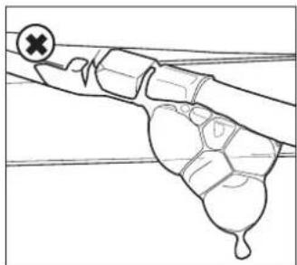
natural_image
Simple line drawing of a hand holding a tool with a cross mark and a droplet, no text or symbols present.natural_image
Line drawing of a gas cylinder with directional arrows indicating flow or movement (no text or symbols)
text_image
barbecook B
text_image
barbc C
text_image
D ! barbecooknatural_image
Technical line drawing of a mechanical component with a cylindrical shaft and directional arrow (no text or symbols)
natural_image
Simple line drawing of a lever with two circular ends and a fulcrum, no text or symbols present.natural_image
Line drawing of a mechanical component with an arrow indicating a process or movement, no text or symbols present.natural_image
Line drawing of a portable stove interior with a handle and cooling fan (no text or symbols)natural_image
Diagram of a bottle with internal spiderweb structure and two insect-like figures (no text or labels)
natural_image
Technical diagram of a mechanical assembly with three curved components and directional arrows indicating motion (no text or symbols)natural_image
Technical line drawing of a mechanical device with two views: top shows a cylindrical component with a cable, bottom shows a circular component with a handle (no text or symbols)natural_image
Technical line drawing of a mechanical component with three top views and a downward arrow indicating process (no text or symbols)4.3. Емайл
natural_image
Technical line drawing of a portable grill with handlebars and control panel (no text or symbols)6.3.1 Myφa A
natural_image
Diagram of a mechanical assembly with threaded components and an upward arrow indicating motion (no text or symbols)
natural_image
Mechanical diagram showing a screw being inserted into a housing with an arrow indicating rotation (no text or symbols present)natural_image
Technical diagram of a mechanical assembly with a bolt and threaded rod (no text or symbols)
text_image
D G6.3.2 Myφa B
natural_image
Technical diagram of a mechanical assembly with threaded connectors and an upward arrow indicator (no text or labels)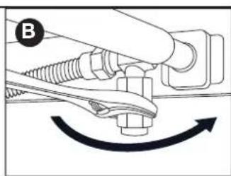
natural_image
Mechanical diagram showing a tool interacting with a bolt and nut, with an arrow indicating rotational motion (no text or symbols present)text_image
Technical diagram showing two mechanical assembly states labeled C and D, with directional arrows indicating movement or force.natural_image
Technical line drawing of a mechanical assembly with no visible text or symbols
natural_image
Line drawing of a mechanical device with no visible text or symbolsnatural_image
Line drawing of a toothbrush with 'barbecook' branding on the lid (no additional text or symbols)natural_image
Pure mechanical diagram showing a pipe joint with a checkmark indicating a detail (no text or symbols)
natural_image
Diagram of a hand holding a small object with a cross mark, no text or symbols presentnatural_image
Line drawing of a gas cylinder with labeled component A and two arrows indicating flow direction (no text or symbols on the diagram itself)
text_image
B barbecook
text_image
C barbic
text_image
D ! barbecooknatural_image
Diagram of a mechanical tool or component with a pointed tip and arrow indicating direction (no text or symbols)natural_image
Simple line drawing of a lever with two circular ends and a fulcrum (no text or symbols)natural_image
Line drawing of a vehicle chassis interior showing internal compartments and a directional arrow (no text or symbols)natural_image
Line drawing of a portable stove interior with a grater and a handle, showing no text or symbolsnatural_image
Diagram of a bottle with internal geometric patterns and two butterflies (no text or symbols)natural_image
Technical line drawing of a mechanical assembly with three curved components and rotational arrows indicating motion (no text or symbols)natural_image
Technical line drawing of a mechanical device with two views: top shows a cylindrical component being inserted, bottom shows a flanged component with a handle (no text or symbols)natural_image
Technical line drawing of a mechanical component with three top views and a downward arrow indicating process (no text or symbols)4.3. Zománc
natural_image
Technical line drawing of a portable grill with handlebars and control panel (no text or symbols)6.3.1. A csatlakozó
natural_image
Mechanical diagram showing a threaded fastener inserted into a pipe, with an upward arrow indicating force direction (no text or symbols present)
natural_image
Mechanical diagram showing a screw being inserted into a housing with an arrow indicating rotational motion (no text or symbols)natural_image
Technical diagram of a mechanical assembly with threaded pipe and valve (no text or symbols)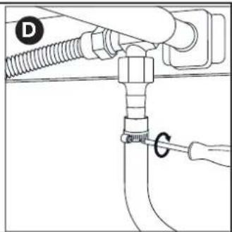
text_image
D G6.3.2. B csatlakozó
natural_image
Diagram of a mechanical assembly with threaded connectors and a valve, showing an upward force arrow (no text or labels)
natural_image
Mechanical diagram showing a fastener or screw assembly with rotational motion indicated by arrows (no text or symbols)natural_image
Mechanical diagram showing a valve assembly with a threaded connector and directional arrow (no text or symbols)
natural_image
Mechanical diagram showing a valve assembly with a rotating knob and directional arrow (no text or symbols)natural_image
Technical line drawing of a mechanical component with no visible text or symbols
natural_image
Line drawing of a mechanical device with no visible text or symbolsnatural_image
Line drawing of a toothbrush with 'barbecook' branding on the lid (no additional text or symbols)natural_image
Pure mechanical diagram showing a lever and pivot point without any text, numbers, or symbols
natural_image
Diagram of a hand holding a small object with a cross symbol, no text or labels presentnatural_image
Line drawing of a gas cylinder with labeled section A and two arrows indicating flow direction (no text or symbols on the diagram itself)
text_image
B barbecook
text_image
C barbc
text_image
D ! barbecook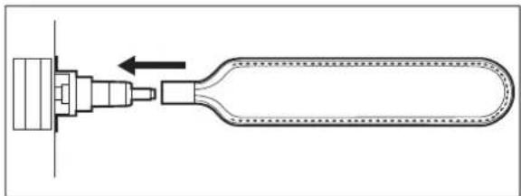
natural_image
Diagram of a mechanical component with a tool inserted into a housing, showing internal structure and motion direction (no text or symbols)natural_image
Simple line drawing of a mechanical lever with two circular components and a fulcrum (no text or symbols)natural_image
Line drawing of a vehicle interior showing a tray with compartments and a handle, no text or symbols presentnatural_image
Line drawing of a portable stove interior with a fire extinguisher being inserted (no text or symbols)natural_image
Diagram of a bottle with internal geometric patterns and two butterflies inside (no text or symbols)
natural_image
Technical diagram of a mechanical assembly with three curved components and rotational arrows indicating motion (no text or symbols)natural_image
Technical line drawing of a mechanical device with two views: top shows a cylindrical component, bottom shows a circular component with a handle (no text or symbols)natural_image
Technical line drawing of a mechanical component with three top views and a downward arrow indicating process (no text or symbols)4.3. Email
natural_image
Technical line drawing of a portable grill with handlebars and control panel (no text or symbols)6.3.1. Cuplajul A
natural_image
Mechanical diagram showing a bolt and nut assembly with an upward arrow indicating motion (no text or symbols)
natural_image
Mechanical diagram showing a lever mechanism with a rotating screw and shaft (no text or symbols)natural_image
Technical diagram of a mechanical assembly with threaded pipe and valve (no text or symbols)
text_image
Diagram showing a pipe connection with labeled parts D and G, likely illustrating a mechanical or fluid system setup.6.3.2 Cuplajul B
natural_image
Mechanical assembly diagram showing a fastener and spring-loaded component with rotational motion arrow (no text or labels)natural_image
Mechanical assembly diagram showing a valve with threaded ports and a directional arrow (no text or symbols)
natural_image
Mechanical assembly diagram showing a valve mechanism with no visible text or symbolsnatural_image
Technical line drawing of a mechanical assembly with no visible text or symbols
natural_image
Line drawing of a medical device with a cap and tubing (no text or symbols)natural_image
Line drawing of a toothpaste brush with 'barbecook' branding on the body (no other text or symbols)7.5. Verificarea scurgerilor de gaz
natural_image
Pure mechanical diagram showing a lever and pivot with no text or symbols
natural_image
Line drawing of a hand gripping a small object with a cross mark, no text or symbols presentnatural_image
Line drawing of a gas cylinder with labeled section A and two arrows indicating flow direction (no text or symbols on the diagram itself)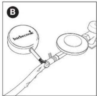
text_image
B barbecook
text_image
C barbc
text_image
D ! barbecook
natural_image
Diagram of a mechanical component with a tool inserted into a housing, showing internal structure and motion direction (no text or symbols)natural_image
Simple line drawing of a mechanical lever or rod with two circular components attached (no text or symbols)natural_image
Technical line drawing of a mechanical component with internal compartments and a directional arrow indicating movement (no text or symbols)natural_image
Line drawing of a kitchen appliance with a grater and a handle, showing no text or symbolsnatural_image
Diagram of a bottle with internal spiderweb structure and two insect-like figures (no text or labels)
natural_image
Technical diagram of a mechanical assembly with three curved components and rotational arrows indicating motion (no text or symbols)| Symbol | Material |
| ● | Enamel |
| ■ | Stainless steel |
| ★ | Powder coated |
[NL]
text_image
Exploded view diagram of a solar panel assembly with numbered components for identification| STELLA 3201BC-GAS-2036 | ||
| 1 BC-SPA-8979 | ● | |
| 2 BC-SPA-9021 | ● | |
| 3 BC-SPA-8938 | ||
| 4 BC-SPA-8995 | ||
| 5 BC-SPA-8984 | ||
| 6 BC-SPA-9370 | ■ | |
| 7 BC-SPA-9022 | ● | |
| 8 BC-SPA-9023 | ● | |
| 9 BC-SPA-9024 | ● | |
| 10 BC-SPA-9025 | ||
| 11 BC-SPA-9026 | ● | |
| 12 BC-SPA-9027 | ||
| 13 BC-SPA-8982 | ||
| 14 BC-SPA-9028 | ||
| 15 BC-SPA-9029 | ||
| 16 BC-SPA-9376 | ■ | |
| 17 BC-SPA-9030 | ■ | |
| 18 BC-SPA-9386 | ||
| 19 BC-SPA-9387 | ||
| 20 BC-SPA-9031 | ||
| 21 BC-SPA-9443 | ||
| STELLA 3201BC-GAS-2036 | ||
| 22 BC | -SPA-9439 | ★ |
| 23 BC | -SPA-9441 | ★ |
| 24 BC | -SPA-9006 | |
| 26 BC | -SPA-9007 | |
| 27 BC | -SPA-8994 | |
| 29 | BC-SPA-9449 | ★ |
| 30 BC | -SPA-9034 | ■ ★ |
| 31 BC | -SPA-9035 | ■ |
| 32 BC | -SPA-9407 | ★ |
| 33 BC | -SPA-9413 | ★ |
| 34 BC | -SPA-9005 | ★ |
| 35 BC | -SPA-9002 | ★ |
| 36 BC | -SPA-9003 | ★ |
| 37 BC | -SPA-9431 | |
| 38 BC | -SPA-9436 | |
| 39 BC | -SPA-8972 | |
| 40 BC | -SPA-8973 | |
| 41 BC | -SPA-9004 | ★ |
| 42 BC | -SPA-9008 | |
1

2

3

text_image
M X4 N X44

natural_image
Technical line drawing of a mechanical enclosure or enclosure with internal compartments and mounting brackets (no text or symbols)5
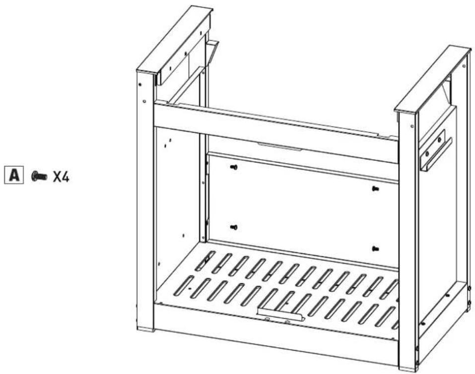
natural_image
Technical line drawing of a metal enclosure with vertical supports and internal compartments (no text or symbols)6
1ST

natural_image
Technical line drawing of a mechanical device with no visible text or symbols
natural_image
Technical line drawing of a mechanical frame with two wheels and a 2nd-order panel (no text or symbols)

3RD

natural_image
Technical line drawing of a mechanical device with no visible text or symbols7

natural_image
Line drawing of a portable gas stove with control panel and wheels (no text or symbols)8

natural_image
Technical line drawing of a mechanical device with wheels and mounting bracket (no text or symbols)
text_image
9 A X4 E X4 H X4
natural_image
Technical line drawing of a wheeled cart with wheels and a labeled component 'A X2' (no text or symbols on the diagram itself)11

natural_image
Technical line drawing of a rectangular enclosure with internal components and a hanging arm, no text or symbols presentS X1
12

natural_image
Technical line drawing of a rectangular enclosure with internal components and a curved pipe (no text or symbols)13

text_image
I J E X2 X2 X214

natural_image
Line drawing of a portable electric grill with wheels and control panel (no text or symbols)15
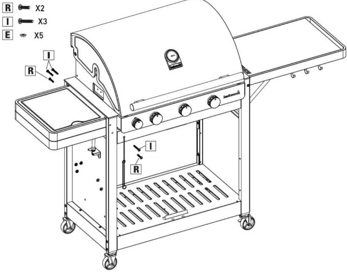
text_image
R X2 I X3 E X5 R I Dinamarack16
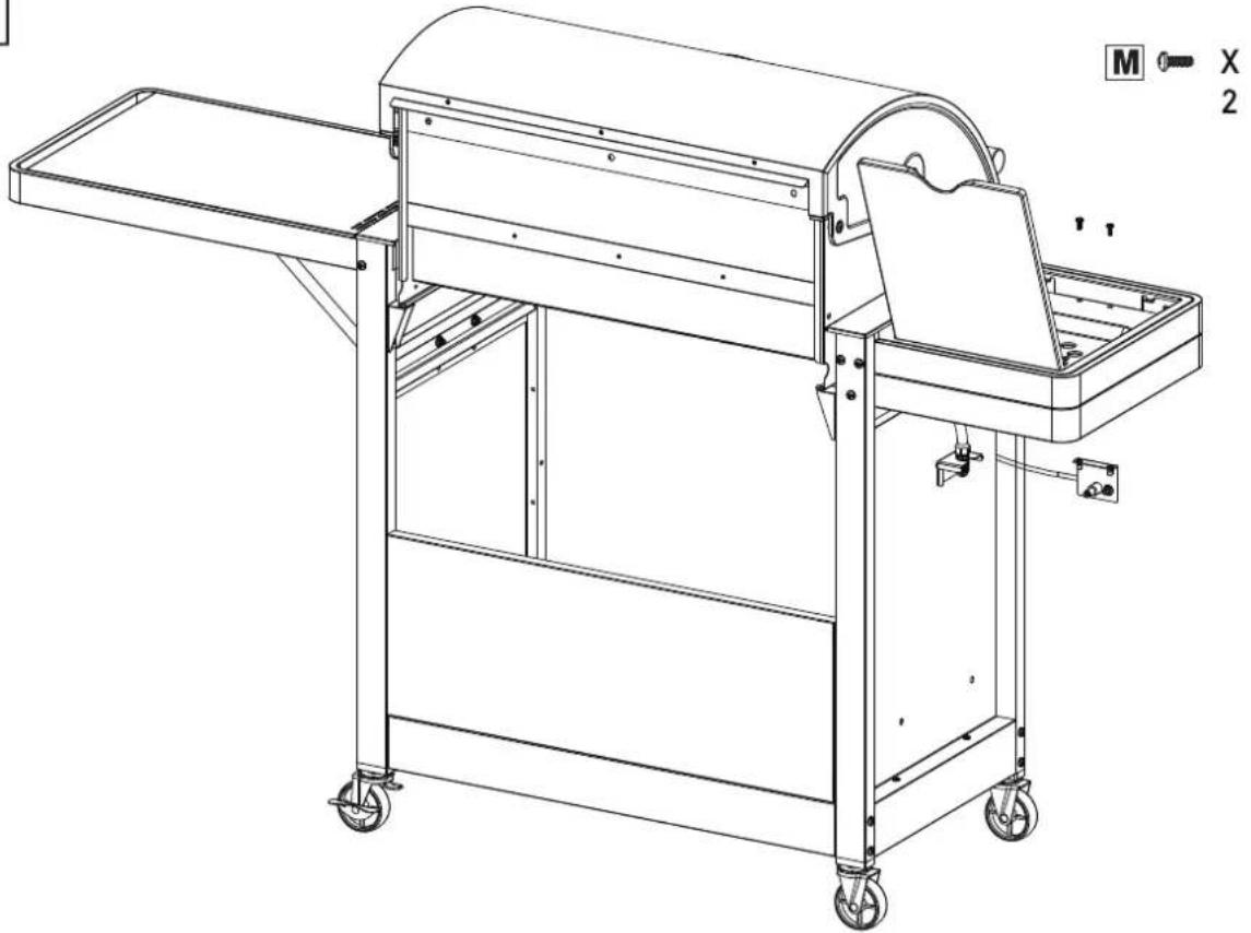
natural_image
Technical line drawing of a mechanical device with wheels and a handle, no text or symbols present17

natural_image
Line drawing of a 1st gas stove with wheels and control panel (no text or symbols)
natural_image
Technical line drawing of a mechanical device with no visible text or symbols18

natural_image
Technical line drawing of a mechanical device with open lid, central tray, and control panel (no text or symbols)M X2
M X1

natural_image
Technical line drawing of a mechanical device with open lid and internal components, showing exploded view (no text or symbols)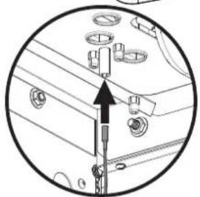
natural_image
Circular diagram showing mechanical components with an upward arrow, no visible text or symbols19

text_image
AND + 1 - + + Not included AA battery LR 6, AM 3 1.5 V
text_image
1ST SB
natural_image
Line drawing of a rectangular electronic device with a circular outline, showing wires and a knob (no text or symbols)20
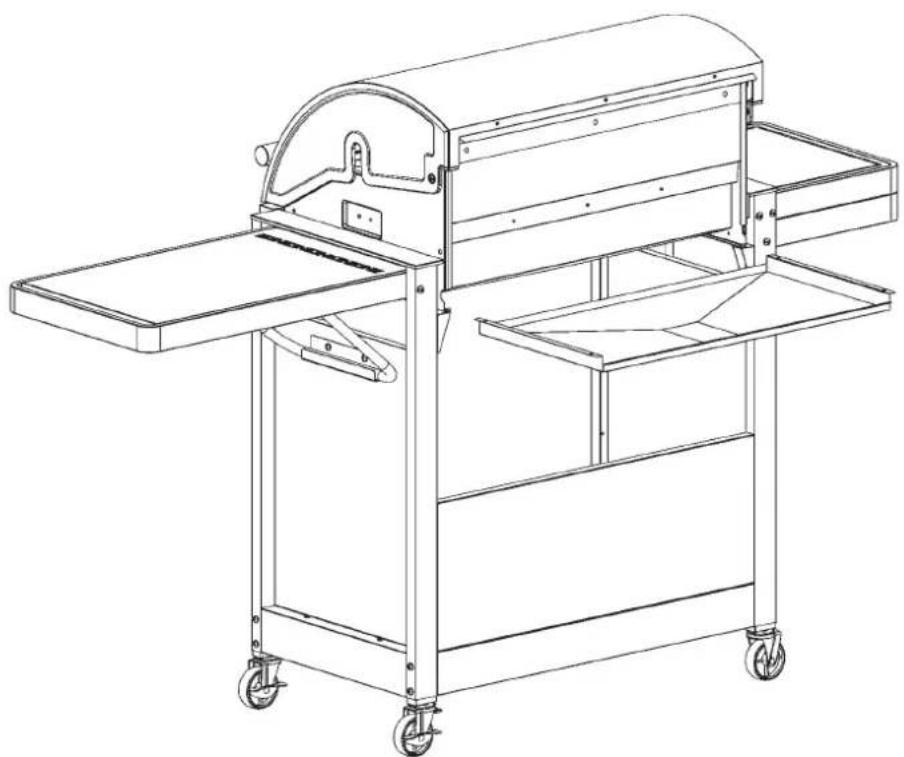
natural_image
Technical line drawing of a mechanical device with wheels and a curved top component (no text or symbols)21

natural_image
Line drawing of a portable electric grill with open doors and wheels, showing internal components and a close-up inset (no text or symbols)22
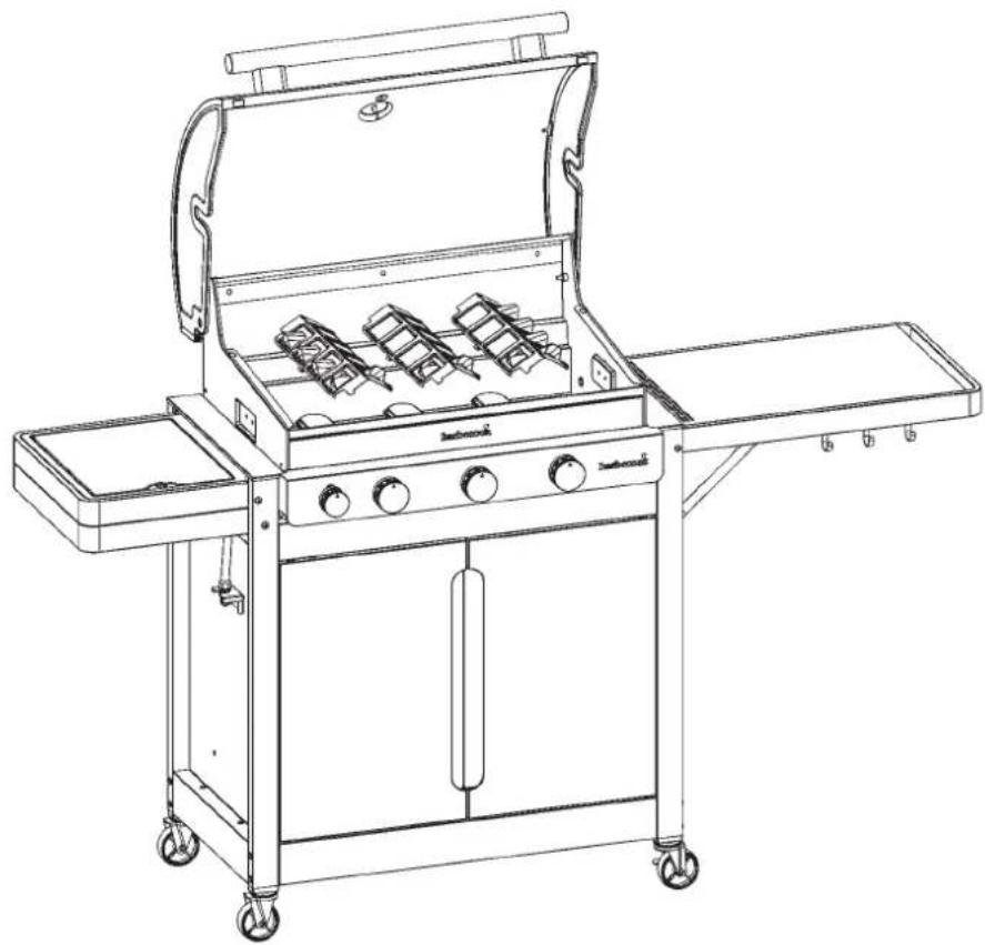
natural_image
Line drawing of a standard electric grill with open chamber, wheels, and control panel (no text or symbols)23

natural_image
Line drawing of a portable electric grill with open top, grating tray, and wheels (no text or symbols)24

natural_image
Line drawing of a portable electric grill with control panel and wheels (no text or symbols)25
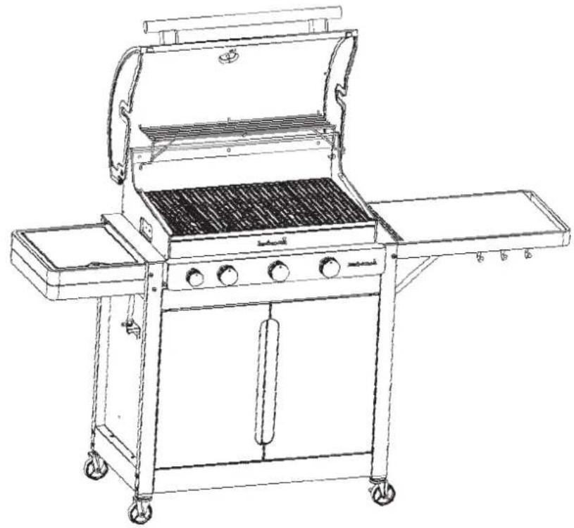
natural_image
Line drawing of a standard electric grill with open top, grating, and side-mounted tray (no text or symbols)26

natural_image
Line drawing of a standard outdoor grill with a curved top and side-mounted dish, mounted on a wheeled cart (no text or symbols)
natural_image
Technical line drawing of a portable gas stove or boiler unit with wheels and control panel (no text or symbols)| A | B | C | D | E | F | G | H | I | J | ||||||
| G30 | G31 | G30 | G31 | G30 | G31 | ||||||||||
| ®barbecook®Stella 3201BC-GAS-2036gas barbecue | LU - NL - DK - FI - SE - CY - CZ -EE - LT - MT - SK - SI - BG - IS - NOTR - HR - RO - IT - HU - LV | 28-30 mbar | propane,butane ortheir mixtures | I 3 B/P (30) | 1,5 Vbattery(not included) | 14.6 kW | 1062 g/h | 1043 g/h | 11.4 kW | 830 g/h | 815 g/h | 3.2 kW | 233 g/h | 229 g/h | |
| BE - FR - IT - LU - IE - GR- PT - ES - CY - CZ - LT - SK - CHSI - LV | 28 30 mbar | butane | I 3 + (28-30/37) | 14.6 kW | 1062 g/h | 1043 g/h | 11.4 kW | 830 g/h | 815 g/h | 3.2 kW | 233 g/h | 229 g/h | |||
| 37 mbar | propane | ||||||||||||||

TYP STELLA 3201/5221 BBCH90805 A
E:
F:
H:
I:
J:
Inspluter hoofdbrander - Injecteur brûleur principale - Injector main burner - Injektor Hauptbrenner - Iniettore bruciatore capo - Investor para hornilla principal - Injector queimador principal - Insprutningspumpen head gasbrännaren - Den store branders dysetype - Suutin pääpolttimen - Tryska hlavnich hořáků - Tryska bčných horákov
Type - Typ - Tipc - Typppi:0.991 (28-30-37 mbar)
Inspulier zijbrander - Injecteur brûleur latérale - Injector side burner - Injektor Selenkocher - Iniettore bruciatore laterale - Inyector para hornilla lateral - Injector queimador lateral - Insprutningspumpen side gasbrännaren - Side branders dysetyoe - Suutin sivupolttimen - Tryska bočního horáku - Tryska bočných horákov - Type - Typ - Tipc - Typppi: 0.88 (28-30-37 mbar)
A: Mark - Marque - Marke - Brand - Mapka - Značka - Marke - Móoka - Marca - Kaubamárk - Tiotemerkói - robna marka - Márka - Ženklas - Prečzimo - Merke - Marka - Marca - Marca - Značka - Znamka - Márke
B: Model - Appliance model - Modell des Geräts - Appliance model - Moden ha ypeža - Model zařízeni - Maskiners model - Movržko ovoškuří - Modelo de aparato - Seadme mudel - Laitteen mallí - model uređaja - A keszůlek tipusa - Modello apparecchio - Prelaiso modelis - Ierices modelis - Model - Model stosowania - Modelo do aparelho - Modelul aparatului - Model zariadenia - Model naprave

BARBECOOK® is a registered brand www.barbecook.com
LivWise Vaartlaan 9 9800 Deinze - Belgium info@livwise.be www.livwise.be
text_image
ALLS VIEW (NEW RANKING) Cartis Sky Blue RRCQ accessories www.12345.com www.12345.comwww.barbecook.com
Register now and get access to:
• Online Product Manuals
• Personalised Grillspiration
• Product Tips & Tricks
- Spare Parts Lists
...
BARBECOOK ^® is a registered brand
www.barbecook.com
f 📷 Barbecook
@barbecook
LivWise
Vaartlaan 9
9800 Deinze - Belgium info@livwise.
be www.livwise.be