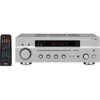
RX497 - Audio System YAMAHA - Free user manual and instructions
Find the device manual for free RX497 YAMAHA in PDF.



| Product type | Stereo receiver |
| Brand | YAMAHA |
| Model | RX497 |
| Dimensions (W x H x D) | 435 x 151 x 308 mm |
| Weight | 8.7 kg |
| Power consumption | 180 W (standby 0.1 W) |
| Power supply | AC 110-240 V, 50/60 Hz (depending on model) |
| Output power (8 Ω, 20 Hz-20 kHz, 0.04% THD) | 75 W + 75 W |
| Main functions | PURE DIRECT, variable LOUDNESS control, sleep timer, remote control, Zone 2 |
| FM/AM Synthesizer | 40 presets (5 groups of 8), automatic and manual memory, station exchange |
| Radio Data System | Europe model only: PS, PTY, RT, CT, EON, PTY SEEK |
| Audio inputs | Phono (MM), CD, MD/TAPE, DVD, DTV/CBL, VCR, TUNER |
| Audio outputs | Speakers A/B, Zone 2, subwoofer, headphones, OUT (REC) |
| Speaker impedance | 4-16 Ω according to IMPEDANCE SELECTOR |
| Required ventilation | Free space: 30 cm above, 20 cm sides and rear |
| Cleaning | Dry, clean cloth, no chemical solvents |
| Safety | Do not expose to rain/moisture, do not open the cabinet, unplug during thunderstorms |
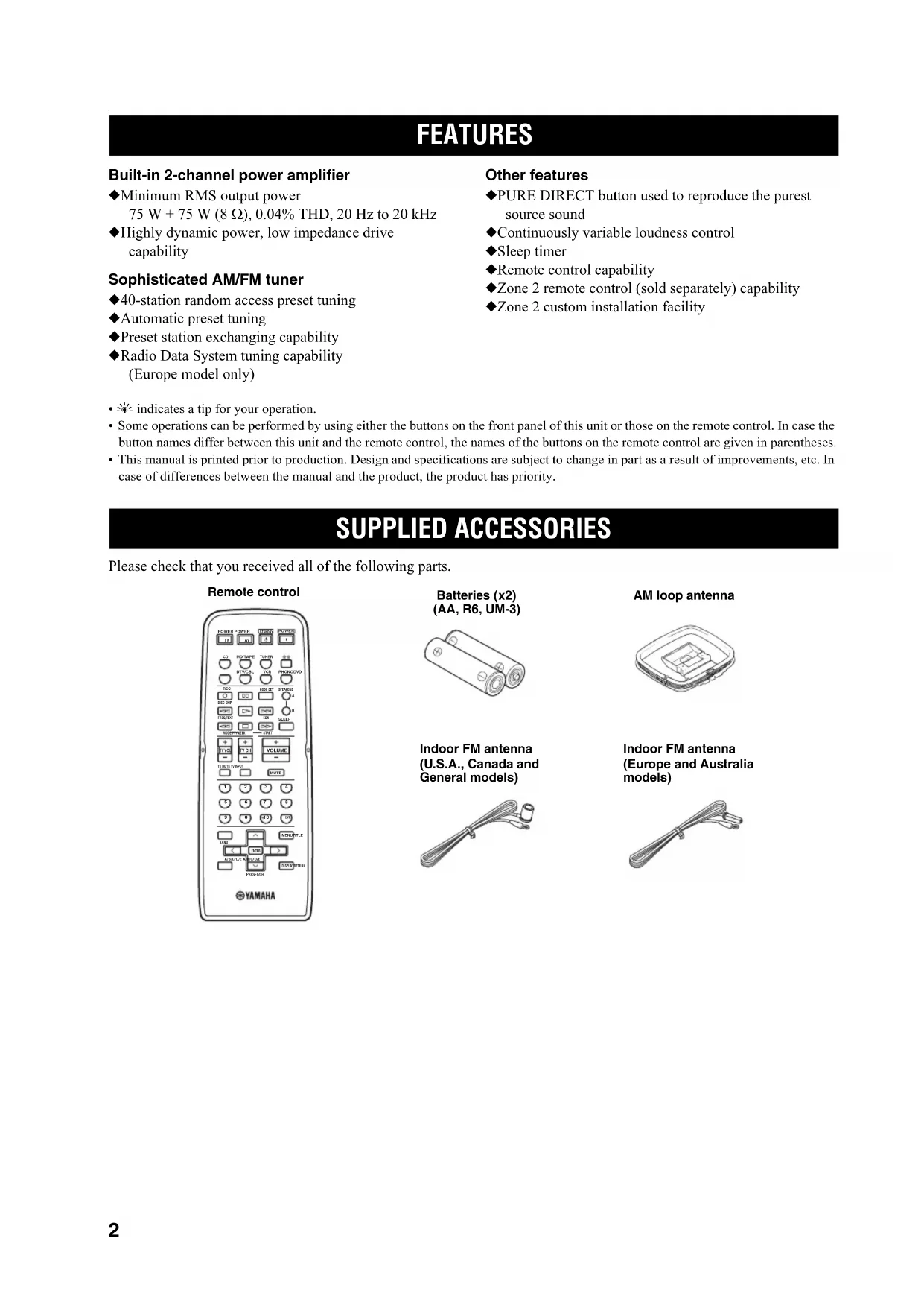
| Supplied accessories | Remote control, batteries (AA x2), AM loop antenna, indoor FM antenna |
Frequently Asked Questions - RX497 YAMAHA
User questions about RX497 YAMAHA
0 question about this device. Answer the ones you know or ask your own.
Ask a new question about this device
Download the instructions for your Audio System in PDF format for free! Find your manual RX497 - YAMAHA and take your electronic device back in hand. On this page are published all the documents necessary for the use of your device. RX497 by YAMAHA.
USER MANUAL RX497 YAMAHA
1 To assure the finest performance, please read this manual carefully. Keep it in a safe place for future reference.
2 Install this sound system in a well ventilated, cool, dry, clean place – away from direct sunlight, heat sources, vibration, dust, moisture, and/or cold. Allow ventilation space of at least 30 cm on the top, 20 cm on the left and right, and 20 cm on the back of this unit.
3 Locate this unit away from other electrical appliances, motors, or transformers to avoid humming sounds.
4 Do not expose this unit to sudden temperature changes from cold to hot, and do not locate this unit in an environment with high humidity (i.e. a room with a humidifier) to prevent condensation inside this unit, which may cause an electrical shock, fire, damage to this unit, and/or personal injury.
5 Avoid installing this unit where foreign objects may fall onto this unit and/or this unit may be exposed to liquid dripping or splashing. On the top of this unit, do not place:
- Other components, as they may cause damage and/or discoloration on the surface of this unit.
– Burning objects (i.e. candles), as they may cause fire, damage to this unit, and/or personal injury.
- Containers with liquid in them, as they may fall and liquid may cause electrical shock to the user and/or damage to this unit.
6Do not cover this unit with a newspaper, tablecloth, curtain, etc. in order not to obstruct heat radiation. If the temperature inside this unit rises, it may cause fire, damage to this unit, and/or personal injury.
7 Do not plug in this unit to a wall outlet until all connections are complete.
8Do not operate this unit upside-down. It may overheat, possibly causing damage.
9Do not use force on switches, knobs and/or cords.
10 When disconnecting the power cable from the wall outlet, grasp the plug; do not pull the cable.
11Do not clean this unit with chemical solvents; this might damage the finish. Use a clean, dry cloth.
12 Only voltage specified on this unit must be used. Using this unit with a higher voltage than specified is dangerous and may cause fire, damage to this unit, and/or personal injury.
YAMAHA will not be held responsible for any damage resulting from use of this unit with a voltage other than specified.
13To prevent damage by lightning, keep the power cord and outdoor antennas disconnected from a wall outlet or the unit during a lightning storm.
14 Do not attempt to modify or fix this unit. Contact qualified YAMAHA service personnel when any service is needed. The cabinet should never be opened for any reasons.
15 When not planning to use this unit for long periods of time (i.e. vacation), disconnect the AC power plug from the wall outlet.
16 Install this unit near the AC outlet and where the AC power plug can be reached easily.
17Be sure to read the “TROUBLESHOOTING” section on common operating errors before concluding that this unit is faulty.
18Before moving this unit, press MASTER ON/OFF to release it outward to the OFF position, and disconnect the AC power plug from the wall outlet.
19VOLTAGE SELECTOR (Asia and General models only)
The VOLTAGE SELECTOR on the rear panel of this unit must be set for your local main voltage BEFORE plugging into the AC main supply. Voltages are:
General model......AC 110/120/220/230–240 V, 50/60 Hz
Asia model ......AC 220/230–240 V, 50/60 Hz
WARNING
TO REDUCE THE RISK OF FIRE OR ELECTRIC SHOCK, DO NOT EXPOSE THIS UNIT TO RAIN OR MOISTURE.
As long as this unit is connected to the AC wall outlet, it is not disconnected from the AC power source even if you turn off this unit by MASTER ON/OFF, or MAIN ZONE ON/OFF and ZONE 2 ON/OFF. In this state, this unit is designed to consume a very small quantity of power.
CONTENTS
INTRODUCTION
FEATURES....2
SUPPLIED ACCESSORIES .... 2
CONTROLS AND FUNCTIONS ....3
Front panel 3
Front panel display 5
Rear panel 6
Remote control....7
Installing batteries in the remote control 9
Using the remote control 9
PREPARATION
CONNECTIONS 10
Connecting speakers.... 11
Connecting the AM and FM antennas.... 12
Connecting the power supply cord 14
Turning on and off this unit.... 14
BASIC OPERATION
PLAYING AND RECORDING 15
Playing a source.... 15
Adjusting the tonal quality.... 16
Recording a source 17
Using the sleep timer 18
Muting the sound output.... 19
FM/AM TUNING 20
Automatic tuning 20
Manual tuning.... 21
Automatic preset tuning.... 22
Manual preset tuning 24
Selecting preset stations.... 25
Exchanging preset stations 25
RADIO DATA SYSTEM
(EUROPE MODEL ONLY) 26
Receiving Radio Data System stations.... 26
Changing the Radio Data System mode 26
PTY SEEK function 27
EON function.... 28
ADVANCED OPERATION
ADVANCED SETUP....29
Changing the ADVANCED SETUP menu
parameters 29
Switching the remote control ID 30
ZONE 2 ....31
Connecting the Zone 2 components .... 31
Controlling Zone 2....32
REMOTE CONTROL FEATURES ....33
Control area 33
Controlling other components 34
Setting remote control codes 35
ADDITIONAL INFORMATION
TROUBLESHOOTING ....36
SPECIFICATIONS....39
FEATURES
Built-in 2-channel power amplifier
◆Minimum RMS output power
75 W + 75 W (8 Ω), 0.04% THD, 20 Hz to 20 kHz
◆Highly dynamic power, low impedance drive capability
Sophisticated AM/FM tuner
◆40-station random access preset tuning
◆Automatic preset tuning
◆Preset station exchanging capability
◆Radio Data System tuning capability (Europe model only)
Other features
◆PURE DIRECT button used to reproduce the purest source sound
◆Continuously variable loudness control
◆Sleep timer
◆Remote control capability
◆Zone 2 remote control (sold separately) capability
◆Zone 2 custom installation facility
• indicates a tip for your operation.
- Some operations can be performed by using either the buttons on the front panel of this unit or those on the remote control. In case the button names differ between this unit and the remote control, the names of the buttons on the remote control are given in parentheses.
- This manual is printed prior to production. Design and specifications are subject to change in part as a result of improvements, etc. In case of differences between the manual and the product, the product has priority.
SUPPLIED ACCESSORIES
Please check that you received all of the following parts.
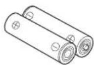
Batteries (x2) (AA, R6, UM-3)
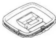
AM loop antenna
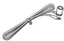
Indoor FM antenna (U.S.A., Canada and General models)
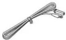
Indoor FM antenna (Europe and Australia models)
CONTROLS AND FUNCTIONS
Front panel

①MASTER ON/OFF
Press inward to the ON position to turn on the power of this unit. Press again to release it outward to the OFF position to turn off this unit.
See page 14 for details.
Note
Even when this unit is turned off, this unit consumes a small amount of power to preserve the memory.
Memory back-up
The memory back-up circuit prevents the stored data from being lost. However, the stored data will be lost if the power cord is disconnected from the AC wall outlet for more than one week.
②MAIN ZONE ON/OFF
Turns on Main Zone of this unit or sets it to the standby mode.
See page 14 for details.
Notes
- This switch is operational only when MASTER ON/OFF is pressed inward to the ON position.
- In the standby mode, this unit consumes a small amount of power to receive infrared signals from the remote control.
③ZONE 2 ON/OFF
Turns on Zone 2 or set it to the standby mode. When Zone 2 is turned on, signals are output at the ZONE 2 OUT jacks.
Note
This switch is operational only when MASTER ON/OFF is pressed inward to the ON position.
④ZONE CONTROL
Press to control the input source of Zone 2.
Notes
- This button is operational only when Zone 2 is turned on.
- When you press this button, the ZONE 2 indicator flashes in the front panel display for approximately 5 seconds. Select the input source of Zone 2 while the indicator is flashing.
- You can select the preset station when TUNER is selected as the input source of Zone 2.
⑤ Remote control sensor
Receives infrared signals from the remote control.
Note
Switch the remote control ID between ID1 and ID2 when using multiple YAMAHA receivers or amplifiers (see pages 29, 30).
⑥Front panel display
Shows information about the operational status of this unit.
CONTROLS AND FUNCTIONS
⑦EDIT
Exchanges the assignment of two preset stations with each other when TUNER is selected as the input source (see page 25).
⑧FM/AM
Switches the reception band between AM and FM when TUNER is selected as the input source (see page 20).
⑨TUNING ◀/▶
Selects the tuning frequency when TUNER is selected as the input source (see page 20).
⑩TUNING MODE
Switches the tuning mode between automatic (the AUTO indicator turns on as a result) and manual (the AUTO indicator turns off as a result) when TUNER is selected as the input source.
⑪MEMORY
Stores a station in the system memory (see page 24). Sets this unit to the automatic preset tuning mode (see page 22).
⑫PURE DIRECT and indicator
Allows you to listen to a source in the purest possible sound. The indicator above it lights up when this function is turned on (see page 16).
⑬MD/TAPE MONITOR
Allows you to listen to the sound played back on the component connected to the MD/TAPE jacks on the rear panel of this unit.
When the tape deck is used for recording, you can also monitor the sound being recorded.
The MD/TAPE MON indicator in the front panel display lights up when this function is turned on.
Notes
- When this function is on (the indicator lights up), MD/TAPE cannot be selected with the INPUT selector.
- To listen to the source selected with the INPUT selector, press again to turn off the function (the indicator turns off as a result).
- When MD/TAPE is selected with the INPUT selector, this function will not turn on even if MD/TAPE MONITOR is pressed.
⑭VOLUME
Increases or decreases the sound output level.
Note
This does not affect the OUT (REC) level.
⑮INPUT selector
Selects the input source you want to listen to or watch.
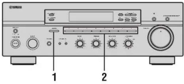
⑯A/B/C/D/E
Selects the preset station group (A to E) when TUNER is selected as the input source (see page 23).
⑰PHONES jack
Outputs audio for private listening with your headphones.
Note
Press SPEAKERS A/B so that the SP A/B indicators turn off before you connect your headphones to the PHONES jack.
⑱SPEAKERS A/B
Turns on or off the speaker set connected to the SPEAKERS A and/or SPEAKERS B terminals on the rear panel each time the corresponding button is pressed (see page 15).
⑲BASS
Increases or decreases the low frequency response. The 0 position produces a flat response (see page 16).
⑳TREBLE
Increases or decreases the high frequency response. The 0 position produces a flat response (see page 16).
②1BALANCE
Adjusts the sound output balance of the left and right speakers to compensate for sound imbalances caused by speaker locations or listening room conditions (see page 16).
⑳LOUDNESS
Retains a full tonal range at any volume level to compensate for the human ears' loss of sensitivity to high and low-frequency ranges at a low volume level (see page 16).
②3Preset station number buttons
(1 to 8)
Selects the preset station number (1 to 8) directly when TUNER is selected as the input source (see page 25).
Front panel display
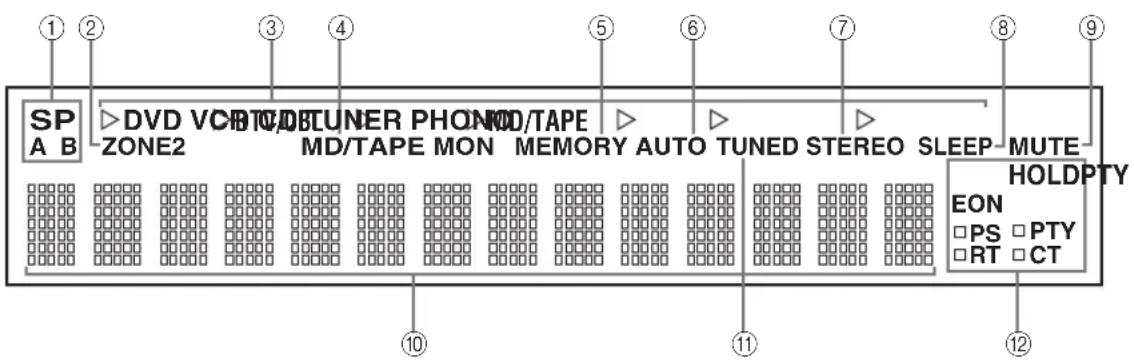
①SP (SPEAKERS) A/B indicators
Light up according to the set of speakers selected. Both indicators light up when both sets of speakers are selected.
②ZONE 2 indicator
Lights up when Zone 2 is turned on.
③Input source indicators
Light up when this unit is in the corresponding mode.
④MD/TAPE MON (MONITOR) indicator
Lights up while the MD/TAPE monitor function is turned on.
⑤MEMORY indicator
Flashes for approximately 5 seconds after MEMORY on the front panel is pressed. While the MEMORY indicator is flashing, store the displayed station in the system memory by using A/B/C/D/E and one of the preset station number buttons on the front panel.
⑥AUTO indicator
Lights up when this unit is in the automatic tuning mode.
⑦STEREO indicator
Lights up when this unit is receiving a strong signal for an FM stereo broadcast while the AUTO indicator is lit.
⑧SLEEP indicator
Lights up when the sleep timer is turned on.
⑨MUTE indicator
Flashes while the MUTE function is turned on.
⑩Multi-information display
Shows information when adjusting or changing settings.
⑪ TUNED indicator
Lights up when this unit is tuned into a station.
■Europe model only
⑫Radio Data System indicators
The box-shaped indicator beside the name of each Radio Data System mode lights up when the corresponding Radio Data System mode is selected.
PTY HOLD indicator
Lights up while searching for stations in the PTY SEEK mode.
EON indicator
Lights up when the Radio Data System station that offers the EON data service is being received.
Rear panel
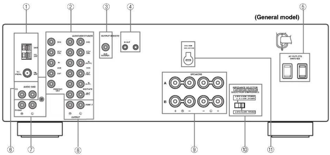
①Antenna terminals
Connect FM and AM antennas.
See page 12 for connections information.
②AUDIO/VIDEO jacks
Connect audio and video components.
See page 10 for connection information.
③SUB WOOFER OUTPUT jack
Connect a subwoofer with built-in amplifier.
④REMOTE jacks
These jacks are used to input/output remote control signals.
See page 31 for connection information.
⑤AC OUTLET(S) (SWITCHED)
Use to supply power to your other audio and video components.
See page 14 for details.
⑥CD jacks
Connect a CD player.
See page 10 for connection information.
⑦PHONO jacks and GND terminal
Connect a turntable.
See page 10 for connection information.
⑧ZONE 2 jacks
Connect a Zone 2 component.
See page 31 for connection information.
⑨SPEAKERS terminals
Connect speakers.
See page 11 for connection information.
⑩IMPEDANCE SELECTOR switch
Switches the impedance setting.
See page 11 for details.
■Asia and General models only
⑪ VOLTAGE SELECTOR
VOLTAGE SELECTOR on the rear panel of this unit must be set for your local main voltage BEFORE plugging the power supply cord into the AC wall outlet.
Voltages are as follows:
Asia model.... AC 220/230-240 V, 50/60 Hz
General model..... AC 110/120/220/230–240 V, 50/60 Hz
Remote control
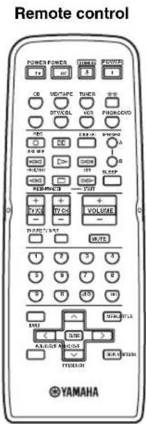
This section describes the function of each button on the remote control used to control this unit or other components made by YAMAHA or other manufacturers. The functions of the buttons used to control your other audio and video components are the same as those of the corresponding buttons on those components. Refer to those components' instruction manuals for details. To operate other components using this remote control, see "REMOTE CONTROL FEATURES" on page 33.
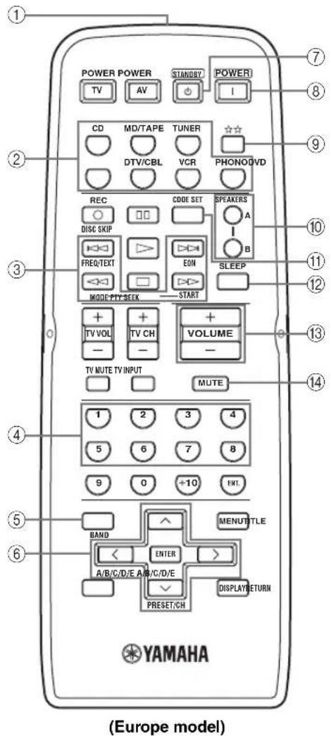
①Infrared signal transmitter
Sends infrared signals.
②Input selector buttons
Select the desired input source and change the control area (see page 33).
③Radio Data System control buttons
Controls the Radio Data System features.
Note
The Radio Data System features (FREQ/TEXT, EON, PTY SEEK MODE and PTY SEEK START) are only applicable to the Europe model and are operational only when TUNER is selected as the input source. For details, see “Receiving Radio Data System stations” on page 26.
④Numeric buttons (1 to 8)
Select the preset station number (1 to 8) when TUNER is selected as the input source.
⑤BAND
Switches to the previously used reception band (FM or AM) when TUNER is selected as the input source.
Note
The frequency of the previously received station is automatically recalled.
⑥A/B/C/D/E < I >
Selects the preset station group (A to E) when TUNER is selected as the input source (see page 25).
PRESET/CH ∧ I ∨
Selects the preset station number (1 to 8) when TUNER is selected as the input source (see page 25).
⑦STANDBY
Sets this unit to the standby mode.
Notes
- This button is operational only when MASTER ON/OFF on the front panel is pressed inward to the ON position.
- In the standby mode, this unit consumes a small amount of power to receive infrared signals from the remote control.
- This button does not set Zone 2 to the standby mode.
⑧ POWER
Turns on this unit.
Notes
- This button is operational only when MASTER ON/OFF on the front panel is pressed inward to the ON position.
• This button does not turn on Zone 2.
CONTROLS AND FUNCTIONS
⑨ ☆☆
Changes the control area (see page 33).
⑩SPEAKERS A/B
Turns on or off the set of speakers connected to the SPEAKERS A and/or SPEAKERS B terminals on the rear panel of this unit when the corresponding button is pressed each time.
⑪CODE SET
Use to set up remote control codes (see page 35).
⑫SLEEP
Sets the sleep timer.
⑬VOLUME +/-
Increases or decreases the sound output level.
Notes
• This does not affect the OUT (REC) level.
- When you press VOLUME +/- to control the sound output level of this unit, VOLUME on the front panel rotates.
⑭MUTE
Mutes the sound output. Press again to restore the sound output to the previous volume level (see page 19).
Note
The sound output to Zone 2 is not muted.
Installing batteries in the remote control
■Notes on batteries
- Change all of the batteries if the operation range of the remote control decreases.
- Use AA, R6, UM-3 batteries for the remote control.
- Make sure that the polarities are correct. See the illustration inside the battery compartment of each remote control.
- Remove the batteries if the remote control is not used for an extended period of time.
- Do not use old batteries together with new ones.
- Do not use different types of batteries (such as alkaline and manganese batteries) together. Read the packaging carefully as these different types of batteries may have the same shape and color.
• We strongly recommend using alkaline batteries. - If the batteries have leaked, dispose of them immediately. Avoid touching the leaked material or letting it come into contact with clothing, etc. Clean the battery compartment thoroughly before installing new batteries.
- Do not throw away batteries with general house waste; dispose of them correctly in accordance with your local regulations.
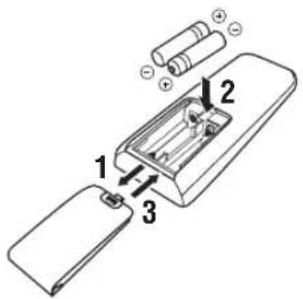
1 Open the battery compartment cover.
2 Insert the supplied batteries in each remote control according to the polarity markings (+ and -) on the inside of the battery compartment.
3 Close the cover back.
Using the remote control
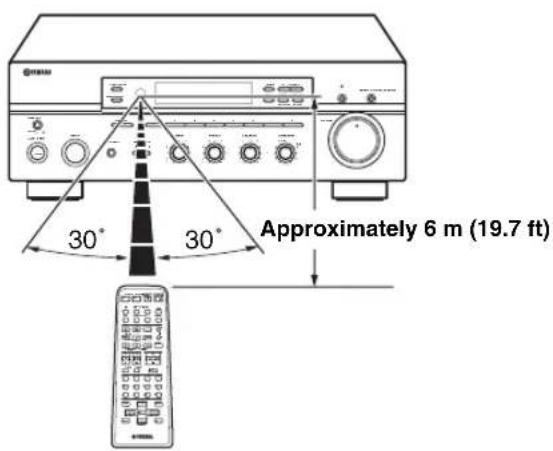
The remote control transmit a directional infrared beam.
Be sure to aim the remote control directly at the remote control sensor on the front panel of this unit or on the infrared signal receiver in Zone 2 during operation.
■Handling the remote control
- The area between the remote control and this unit (or the infrared signal receiver in Zone 2) must be clear of large obstacles.
- Do not spill water or other liquids on the remote control.
- Do not drop the remote control.
- Do not leave or store the remote control in the following types of conditions:
- places of high humidity, such as near a bath
— places of high temperature, such as near a heater or a stove
— places of extremely low temperatures - dusty places
- Do not expose the remote control sensor to strong lighting, in particular, an inverter type fluorescent lamp; otherwise, the remote control may not work properly. If necessary, position this unit away from direct lighting.
CONNECTIONS
CAUTION
- Do not connect this unit or other components to the main power until all connections between components are complete.
- Do not let the bare speaker wires touch each other or do not let them touch any metal part of this unit. This could damage this unit and/or the speakers.
- All connections must be correct: L (left) to L, R (right) to R, “+” to “+” and “−” to “−”. If the connections are faulty, no sound will be heard from the speakers, and if the polarity of the speaker connections is incorrect, the sound will be unnatural and lack bass. Also, refer to the owner’s manual for each of your components.
- Use the RCA type pin plug cables for audio and video components except speakers.

- The PHONO jacks are designed to connect a turntable with an MM or high-output MC cartridge. If you have a turntable with a low-output MC cartridge, use an in-line boosting transformer or an MC-head amplifier when connecting your turntable to the PHONO jacks.
- Connect your turntable to the GND terminal to reduce noise in the signal. However, you may hear less noise without the connection to the GND terminal for some record players.
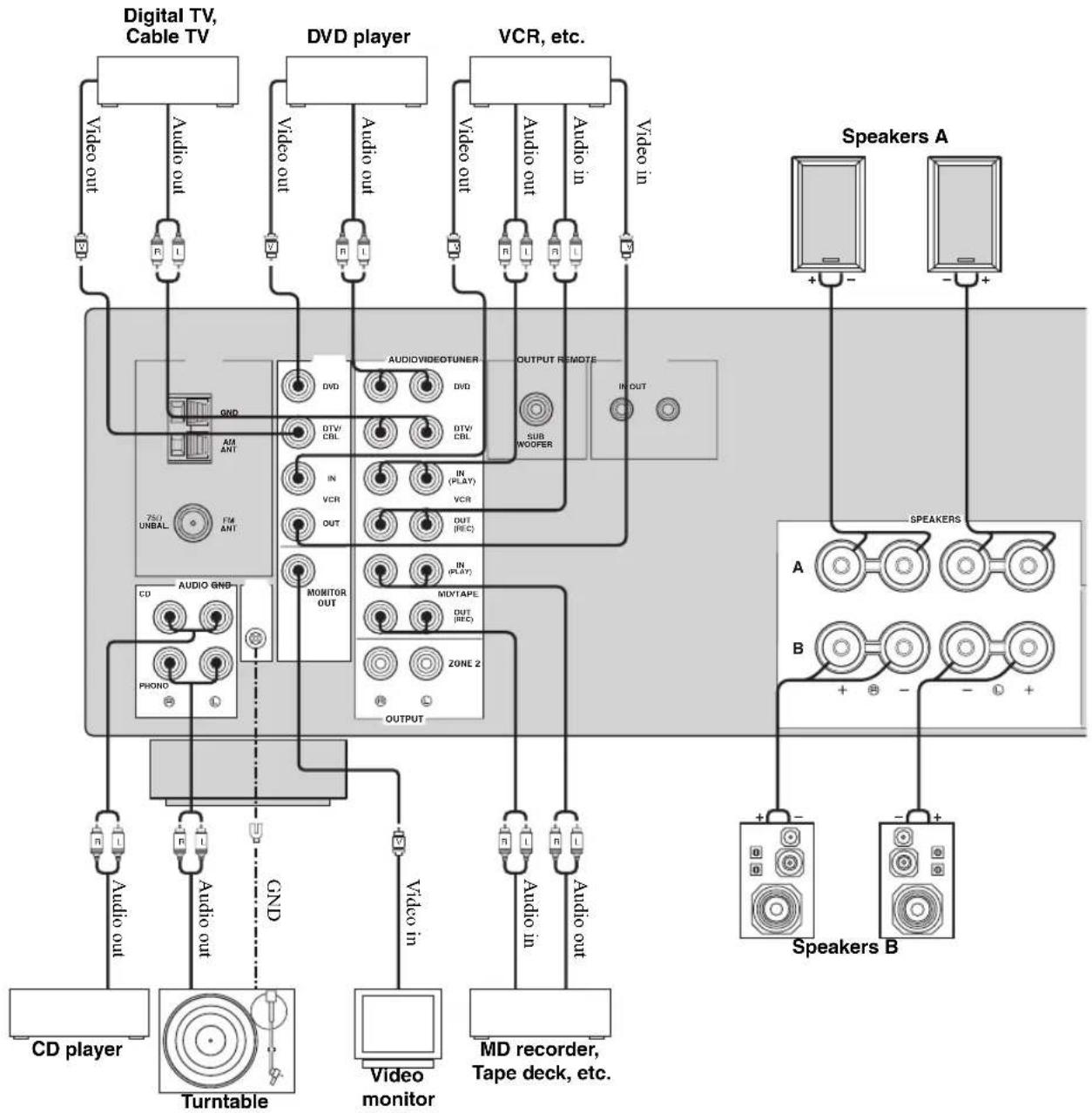
flowchart
graph TD
    A["Digital TV, Cable TV"] -->|Video out| B["Audio out"]
    A -->|GND| C["AM ANT"]
    A -->|75/1 UNBAL| D["TM ANT"]
    A -->|Audio out| E["CD player"]
    A -->|Audio in| F["Turntable"]
    G["DVD player"] -->|Video out| H["Audio out"]
    G -->|VCR| I["Video monitor"]
    G -->|Audio out| J["Audio in"]
    K["VCR, etc."] -->|Video out| L["Audio out"]
    K -->|Audio in| M["Audio in"]
    N["Speaker A"] -->|+ - | O["Speakers A"]
    N -->|- - | P["Speakers B"]
    Q["Speaker B"] -->|+ - | R["Speakers B"]
    Q -->|- - | S["Speakers B"]
    T["Speaker A"] -->|IN OUT| U["AUDIOVIDEOTUNER"]
    T -->|DOUT (REC)| V["MONITOR OUT"]
    T -->|IN (PLAY)| W["MIXTAPE"]
    T -->|VCR| X["ZONE 2"]
    Y["Speaker B"] -->|+ - | Z["MD recorder, Tape deck, etc."]
Connecting speakers
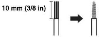
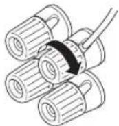
1 Remove approximately 10 mm (3/8 in) of insulation from the end of each speaker cable and twist the exposed wires of the cable together to prevent short circuits.
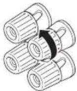
2 Unscrew the knob.
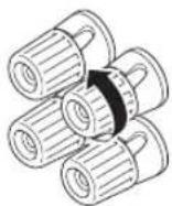
Red: positive (+) Black: negative (−)
3 Insert one bare wire into the hole in the side of each terminal.
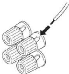
natural_image
Diagram of three cylindrical objects with a curved arrow pointing to one (no text or symbols)Red: positive (+) Black: negative (−)
4 Tighten the knob to secure the wire.
Red: positive (+) Black: negative (−)
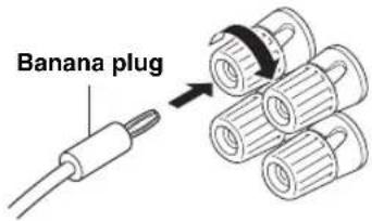
■Connecting the banana plug (U.S.A., Canada, Australia and General models only)
First, tighten the knob and then insert the banana plug into the end of the corresponding terminal.
Notes
- One or two speaker sets can be connected to this unit. If you use only one speaker set, connect it to either the SPEAKERS A or B terminals.
- Use speakers with the specified impedance shown on the rear panel of this unit.
■IMPEDANCE SELECTOR
CAUTION
Do not slide the IMPEDANCE SELECTOR switch while the power of this unit is turned on, as doing so may damage the unit.
Select the switch position (left or right) according to the impedance of the speakers in your system.
| Switch position | Impedance level |
| Right | If you use one set (A or B), the impedance of each speaker must be 8 Ω or higher. |
| If you use two sets (A and B), the impedance of each speaker must be 16 Ω or higher. | |
| Left | If you use one set (A or B), the impedance of each speaker must be 4 Ω or higher. |
| If you use two sets (A and B), the impedance of each speaker must be 8 Ω or higher. |
Notes
- The Canada model cannot use two speaker sets (A and B) simultaneously when the IMPEDANCE SELECTOR switch is slid to the right position.
- If this unit fails to turn on, the IMPEDANCE SELECTOR switch may not be fully slid to either position. If this is the case, slide the switch all the way to either position when the power supply to this unit is completely cut off.
Connecting the AM and FM antennas
Both AM and FM indoor antennas are included with this unit. In general, these antennas should provide sufficient signal strength. Connect each antenna correctly to the designated terminals.
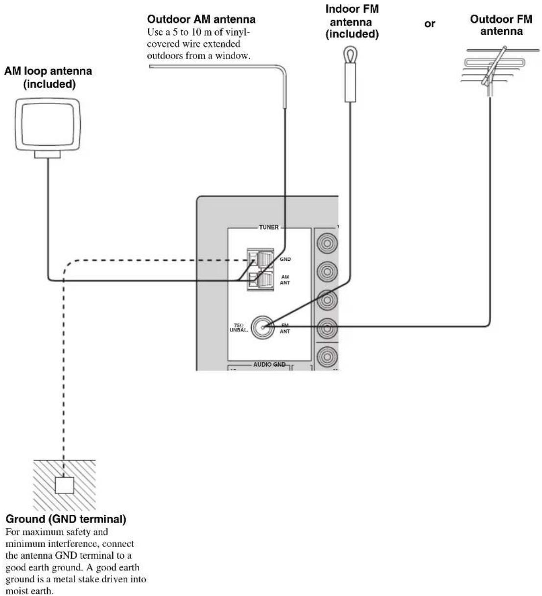
Notes
- A properly installed outdoor antenna provides clearer reception than an indoor one. If you experience poor reception quality, an outdoor antenna may improve the quality. Consult your nearest authorized YAMAHA dealer or service center about outdoor antennas.
- If you connect an outdoor FM antenna to this unit, do not connect the indoor FM antenna to this unit.
- To minimize interference from automobile ignition, locate the antenna as far from heavy traffic as possible.
- Keep the feeder cable or coaxial cable as short as possible. Do not bundle or roll up excess cable.
- The antenna should be placed at least 2 meters from reinforced concrete walls or metal structures.
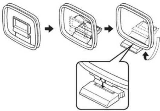
■Connecting the AM loop antenna
1 Set up the AM loop antenna.
flowchart
graph TD
    A["Screen with monitor"] --> B["Computer monitor with internal components"]
    B --> C["Monitor with base station"]
    C --> D["Base station"]
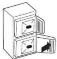
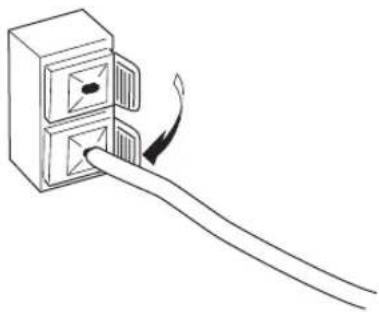
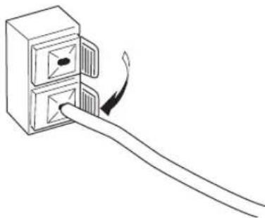
2 Press and hold the tab.
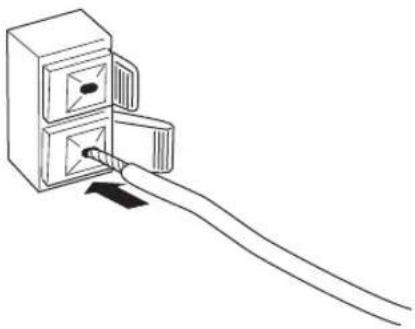
3 Insert the AM loop antenna lead wires into the AM ANT terminal.
natural_image
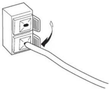
Line drawing of a cable inserted into a double door with a pointer (no text or symbols)4 Release the tab.
natural_image
Line drawing of a hand inserting a card into a box (no text or symbols)5 Repeat steps 2 to 4 to insert the AM loop antenna lead wires into the GND terminal.
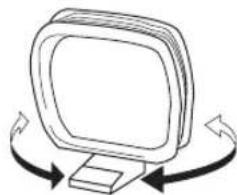
6 Orient the AM loop antenna for the best reception.
natural_image
Simple line drawing of a computer monitor with curved arrows indicating rotation or movement (no text or symbols)Notes
• The AM loop antenna should be placed away from this unit.
- A properly installed outdoor antenna provides clearer reception than an indoor one. If you experience poor reception quality, an outdoor antenna may improve the quality. It is recommended that you should connect a 5 to 10m of vinyl-covered wire to the AM ANT terminal and extend it outdoors from a window. Consult your nearest authorized YAMAHA dealer or service center about outdoor antennas.
- The AM loop antenna should always be connected, even if an outdoor AM antenna is connected to this unit.
Connecting the power supply cord
Plug the power supply cord into the AC wall outlet after all other connections are complete.
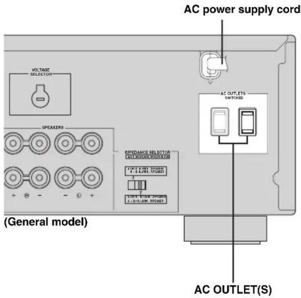
■AC OUTLET(S) (SWITCHED)
Australia model .... 1 outlet Other models .... 2 outlets
Use these outlets to connect the power supply cords from your other components to this unit. The outlets supply power to any connected components whenever the power of this unit is turned on. For information on the maximum power (total power consumption of components), see "SPECIFICATIONS" on page 39.
Turning on and off this unit
When all connections are complete, turn on the power of this unit.
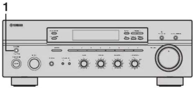
1 Press MASTER ON/OFF on the front panel inward to the ON position to turn on the power of this unit.
Main Zone of this unit turns on.

- You can set Main Zone of this unit to the standby mode by pressing MAIN ZONE ON/OFF on the front panel or STANDBY on the remote control.
Press MAIN ZONE ON/OFF on the front panel or POWER on the remote control to turn Main Zone on again. - Press MASTER ON/OFF on the front panel again to release it outward to the OFF position to turn off this unit.
#
While MASTER ON/OFF on the front panel is pressed inward to the ON position, you can turn on Zone 2 or set it to the standby mode independently (see page 32).
PLAYING AND RECORDING
CAUTION
Extreme caution should be exercised when you play back CDs encoded in DTS.
If you play back a CD encoded in DTS on a DTS-incompatible CD player, you will only hear some unwanted noise that may damage your speakers. Check whether your CD player supports CDs encoded in DTS. Also, check the sound output level of your CD player before you play back a CD encoded in DTS.
Playing a source
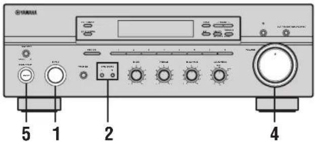
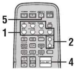
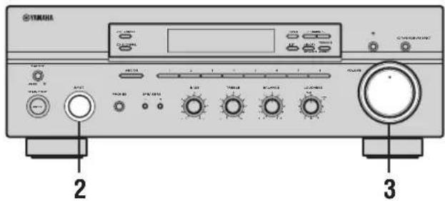
1 Rotate the INPUT selector on the front panel (or press one of the input selector buttons on the remote control) to select the desired input source.
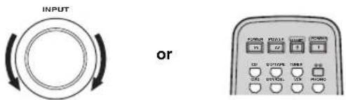
Front panel Remote control
2 Press SPEAKERS A and/or SPEAKERS B on the front panel or on the remote control to select speakers A and/or speakers B.
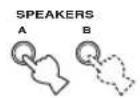
Front panel
or
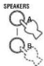
Remote control
Notes
- Both SPEAKERS A and B can be selected.
- Make sure that the IMPEDANCE SELECTOR switch is correctly set (see page 11).
3 Play the source.
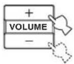
4 Rotate VOLUME on the front panel (or press VOLUME +/- on the remote control) to adjust the sound output level.
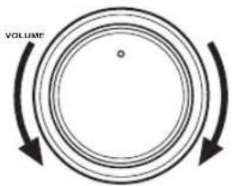
Front panel
or
Remote control
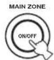
5 Press MAIN ZONE ON/OFF on the front panel again (or press STANDBY on the remote control) to finish using this unit and set it to the standby mode.
Front panel
or

Remote control
Adjusting the tonal quality
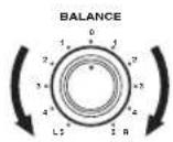
■Adjusting the BALANCE control
Adjusts the sound output balance of the left and right speakers to compensate for sound imbalance caused by speaker locations or listening room conditions.
■Using the PURE DIRECT button
Routes input signals from your audio sources so that the input signals bypass the BASS, TREBLE, BALANCE and LOUDNESS controls, thus eliminating any alterations to the audio signals and creating the purest possible sound.

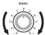
■Adjusting the BASS and TREBLE controls
Adjust the high and low frequency response.
BASS
Increases or decreases the low frequency response.
TREBLE
Increases or decreases the high frequency response.

■Adjusting the LOUDNESS control
Retains a full tonal range at any volume level, thus compensating for the human ears' loss of sensitivity to high and low-frequency ranges at a low volume level.
CAUTION
If the PURE DIRECT button is turned on with the LOUDNESS control set at a certain level, the input signals bypass the LOUDNESS control, resulting in a sudden increase in the sound output level. To prevent your ears or the speakers from being undesirably damaged, be sure to press the PURE DIRECT button after lowering the sound output level or after checking that the LOUDNESS control is properly set.
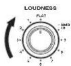
1 Rotate the LOUDNESS control on the front panel to the FLAT position.
2 Rotate VOLUME on the front panel (or press VOLUME +/- on the remote control) to set the sound output level to the loudest listening level that you would listen to.
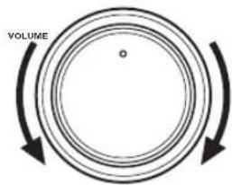
Front panel
or
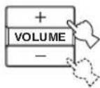
Remote control
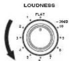
3 Rotate the LOUDNESS control until the desired volume is obtained.
Recording a source
Notes
- The VOLUME, BASS, TREBLE, BALANCE and LOUDNESS controls and the PURE DIRECT buttons have no effect on the source being recorded.
- Check the copyright laws in your country to record from records, CDs, radio, etc. Recording copyright-protected material may infringe on copyright laws.
1 Play the selected source to record from.
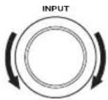
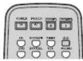
2 Rotate the INPUT selector on the front panel (or press one of the input selector buttons on the remote control) to select the source you want to record from.
Front panel
or
Remote control
Note
You cannot select any input source while the MD/TAPE MON indicator in the front panel display lights on.
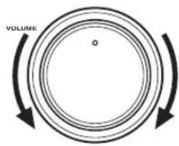
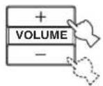
3 Rotate VOLUME on the front panel (or press VOLUME +/- on the remote control) to adjust the sound output level of the selected source to record from.
Front panel
or
Remote control
4 Begin recording on the MD recorder, the tape deck or the VCR connected to this unit.
[NO TEXT]
If the 3-head tape deck is used for recording, you can monitor the sound of recording by pressing MD/TAPE MONITOR on the front panel.
Using the sleep timer
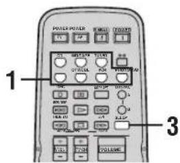
Use this feature to automatically set this unit to the standby mode after a certain amount of time. The sleep timer is useful when you are going to sleep while this unit is playing or recording a source. The sleep timer also automatically turns off any external components connected to the AC OUTLET(S).
Notes
- The sleep timer can only be set with the remote control.
- The sleep timer automatically turns off Zone 2. However, the power of Zone 2 components are not turned off.
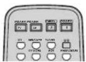
1 Press one of the input selector buttons on the remote control to select an input source.
2 Start playback on the selected input source.
3 Press SLEEP repeatedly to set the amount of time before this unit is set to the standby mode.
Each time you press SLEEP, the front panel display changes as shown below.

flowchart
graph TD
    A["SLEEP"] --> B["→ SLEEP 120 min → SLEEP 90 min"]
    B --> C["SLEEP OFF ← SLEEP 30 min ← SLEEP 60 min"]
The SLEEP indicator flashes while switching the amount of time for the sleep timer.

4 Press SLEEP repeatedly so that SLEEP OFF appears in the front panel display.

After a few seconds, SLEEP OFF disappears from the front panel display, and the SLEEP indicator turns off.

The sleep timer setting can also be canceled by pressing STANDBY on the remote control (or MAIN ZONE ON/OFF or MASTER ON/OFF on the front panel) to set this unit to the standby mode.
Muting the sound output
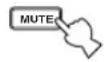
1 Press MUTE on the remote control to mute the sound output.
The MUTE indicator flashes in the front panel display.


After a few seconds, MUTE ON disappears from the front panel display.
2 Press MUTE on the remote control again to resume the sound output.
The MUTE indicator disappears from the front panel display.
FM/AM TUNING
There are 2 tuning methods; automatic and manual. Select either method according to your preference and the strength of station signals.
Automatic tuning
Automatic tuning is effective when station signals are strong and there is no interference.
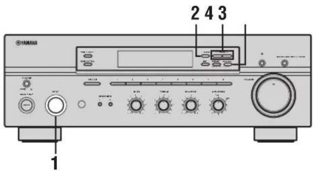
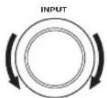
1 Rotate the INPUT selector (or press TUNER on the remote control) to select TUNER as the input source.
Front panel
or

Remote control
2 Press FM/AM on the front panel to select the reception band (FM or AM).
FM or AM appears in the front panel display.

3 Press TUNING MODE on the front panel so that the AUTO indicator lights up in the front panel display.


AUTO
Lights up
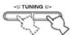
4 Press TUNING ◀/▷ once to begin automatic tuning.
Press ▷ to tune into a higher frequency.
Press to tune into a lower frequency.
Notes
- When you tune into a station, the frequency of the received station is shown in the front panel display.
- To search for another station, press TUNING / once more.
- If the tuning search does not stop at the desired station because the station signals are weak, try using the manual tuning method.
Manual tuning
Manual tuning is effective when station signals are weak.
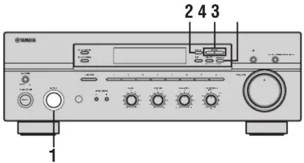
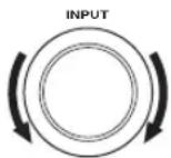
1 Rotate the INPUT selector (or press TUNER on the remote control) to select TUNER as the input source.
Front panel
or

Remote control
2 Press FM/AM on the front panel to select the reception band (FM or AM).
FM or AM appears in the front panel display.

3 Press TUNING MODE on the front panel so that the AUTO indicator disappears from the front panel display.


AUTO
Disappears
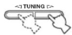
4 Press TUNING ◀/▷ to manually tune into the desired station.
Hold down the button to continue tuning search.
Notes
- When you tune into a station, the frequency of the received station is shown in the front panel display.
- If you tune into an FM station, it is automatically received in the monaural mode to increase signal quality.
Automatic preset tuning
You can use the automatic preset tuning method to automatically store FM stations. This function enables this unit to automatically tune into FM stations with strong signals and store up to 40 (8 stations in each of the 5 groups, A1 to E8) of those received stations in order. You can then easily recall any preset stations by selecting the preset station numbers where they are stored.
Notes
- Any station data stored under a preset station number is cleared when you store a new station under that preset station number.
- If the number of received stations does not reach 40 (E8), automatic preset tuning automatically stops once searching all available stations are tuned into and stored.
- Only FM stations with sufficient signal strength are stored automatically by automatic preset tuning. If the station you want to store is weak in signal strength, try using the manual preset tuning method.
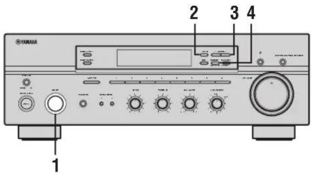
1 Rotate the INPUT selector (or press TUNER on the remote control) to select TUNER.
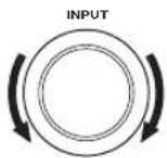
Front panel
or

Remote control
2 Press FM/AM on the front panel to select FM as the reception band.
FM appears in the front panel display.

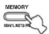
3 Press and hold MEMORY on the front panel for more than 3 seconds.
The preset station group and the MEMORY and AUTO indicators flash in the front panel display.

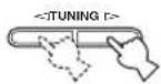
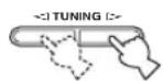
4 Press TUNING ◀/▷ once to begin automatic preset tuning.
Press ▷ to tune into higher frequencies.
Press to tune into lower frequencies.
When automatic preset tuning is complete, the frequency of the last preset station is shown in the front panel display.
Notes
- If TUNING / is not pressed within approximately 5 seconds while the MEMORY and AUTO indicators are flashing, automatic preset tuning automatically begins from the currently displayed frequency and proceeds toward higher frequencies.
- Received stations are sequentially programmed to 8 stations in each preset station group. If 8 stations are all programmed in a preset station group, another 8 stations are sequentially programmed in the next preset station group.
■Customized automatic preset tuning
You can specify a preset station group and a preset station number from which this unit stores the FM stations received by automatic preset tuning.
1 Press and hold MEMORY on the front panel for more than 3 seconds.
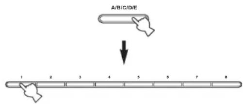
2 Press A/B/C/D/E and then press one of the preset station number buttons on the front panel to select the preset station group and the preset station number where the first received station will be stored.
For example, if you select C5, the first received station is automatically programmed to C5 and the next received stations are sequentially programmed to C6, C7, etc.
3 Press TUNING ◀/▷ on the front panel to begin automatic preset tuning.
Press to tune into higher frequencies.
Press to tune into lower frequencies.
When automatic preset tuning is complete, the frequency of the last preset station is shown in the front panel display.
Note
Automatic preset tuning stops when the received stations have all been stored up to E8.
Manual preset tuning
You can also manually store up to 40 stations (8 stations in each of the 5 groups, A1 to E8). You can then easily recall any preset stations by selecting the preset station numbers where they are stored.
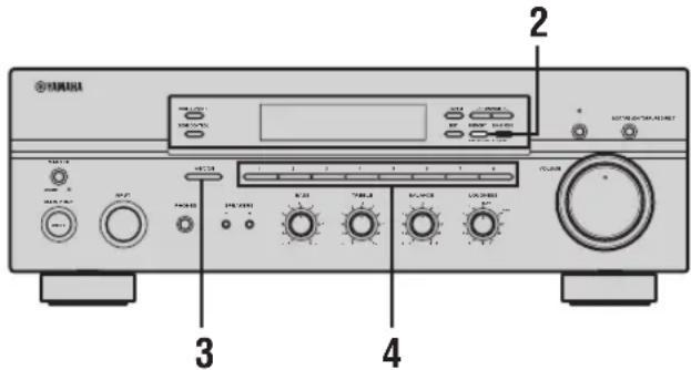
1 Repeat steps 1 to 4 in "Automatic tuning" or in "Manual tuning" to tune into a station.
When you tune into a station, the frequency of the received station is shown in the front panel display.
2 Press MEMORY on the front panel.
The MEMORY indicator flashes in the front panel display for approximately 5 seconds.

MEMORY
Flashes
3 Press A/B/C/D/E on the front panel repeatedly to select a preset station group (A to E).
The selected preset station group is shown in the front panel display.
4 Press one of the preset station number buttons on the front panel to select a preset station number (1 to 8) where you want to store the station.

Note
This operation must be done within 5 seconds while the MEMORY indicator is flashing in the front panel display. Otherwise, the manual preset tuning process is automatically canceled.
5 Press MEMORY on the front panel to store the station.
6 Repeat steps 1 to 5 to store other stations.
Notes
- Any station data stored under a preset station number is cleared when you store a new station under that preset station number.
- The reception mode (stereo or monaural) is stored along with the station frequency.
Selecting preset stations
You can tune into the desired station simply by selecting the preset station number where it is stored.
1 Press A/B/C/D/E on the front panel repeatedly (or press A/B/C/D/E < / > on the remote control) to select a preset station group (A to E).
The selected preset station group is shown in the front panel display.
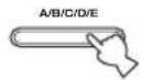
Front panel
or
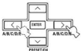
flowchart
graph TD
    A["ENTER"] --> B["A/B/C/D/E"]
    A --> C["A/B/C/D/E"]
    A --> D["PRESET/CH"]
Remote control
2 Press one of the preset station number buttons on the front panel (or PRESET <//> on the remote control) to select a preset station number (1 to 8).
The preset station number appears in the front panel display along with the reception band and the frequency.

Front panel
or
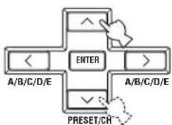
flowchart
graph TD
    A["ENTER"] --> B["A/B/C/D/E"]
    A --> C["A/B/C/D/E"]
    A --> D["PRESET/CH"]
    style A fill:#f9f,stroke:#333
    style B fill:#ccf,stroke:#333
    style C fill:#ccf,stroke:#333
    style D fill:#cfc,stroke:#333
Remote control
Exchanging preset stations
You can exchange the assignment of two preset stations with each other. The following procedure describes an example where a preset station E1 is exchanged with another preset station A5.
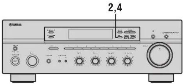
1 Repeat steps 1 and 2 in "Selecting preset stations" to select a preset station E1.
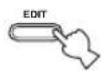
2 Press EDIT on the front panel.
E1 and the MEMORY indicator flash in the front panel display.

MEMORY Flashes
3 Repeat steps 1 and 2 in "Selecting preset stations" to select another preset station A5.
A5 and the MEMORY indicator flash in the front panel display.
MEMORY Flashes
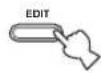
4 Press EDIT on the front panel again.
E1-A5 appears in the front panel display, indicating that the two preset station assignments have been exchanged.
RADIO DATA SYSTEM (EUROPE MODEL ONLY)
Receiving Radio Data System stations
Radio Data System is a data transmission system used by FM stations in many countries. The Radio Data System function is carried out among the network stations.
This unit can receive various Radio Data System data such as PS (Program Service name), PTY (Program Type), RT (Radio Text), CT (Clock Time), EON (Enhanced Other Networks) when receiving Radio Data System broadcasting stations.
■PS (Program Service name) mode
The name of the Radio Data System station being received is displayed.
■PTY (Program Type) mode
There are 15 program types to classify Radio Data System stations.
| NEWS News | |
| AFFAIRS Current affairs | |
| INFO General information | |
| SPORT Sports | |
| EDUCATE Education | |
| DRAMA Drama | |
| CULTURE Culture | |
| SCIENCE Science | |
| VARIED Light entertainment | |
| POP M | Pops |
| ROCK M | Rock |
| M.O.R. M | Middle-of-the-road music (easy-listening) |
| LIGHT M | Light classics |
| CLASSICS | Serious classics |
| OTHER M | Other music |
■RT (Radio Text) mode
Information about the program (such as the title of the song or name of the singer) on the Radio Data System station being received is displayed using a maximum of 64 alphanumeric characters, including the umlaut symbol. If other characters are used for RT data, they are displayed with an underbar (_).
■CT (Clock Time) mode
The current time is displayed and updated every minute.
If the data are accidentally cut off, "CT WAIT" may appear.
■EON (Enhanced Other Networks)
See "EON function" on page 28.
Changing the Radio Data System mode
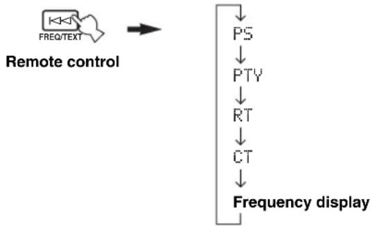
Four modes are available for displaying Radio Data System data. The PS, PTY, RT and/or CT indicators that correspond to the Radio Data System data services offered by the station light up in the front panel display.
1 Press TUNER on the remote control to set this unit to tuner mode.

2 Press FREQ/TEXT repeatedly on the remote control to display the various Radio Data System data offered by the transmitting station.
flowchart
graph TD
    A["Remote control"] --> B["PS"]
    B --> C["PTY"]
    C --> D["RT"]
    D --> E["CT"]
    E --> F["Frequency display"]
Notes
- Do not press FREQ/TEXT until a Radio Data System indicator lights up in the front panel display. You cannot change the mode if you press the button prior to this. This is because this unit has not finished receiving all of the Radio Data System data from the station.
- Radio Data System data not offered by the station cannot be selected.
- This unit cannot utilize the Radio Data System data source if the signal received is not strong enough. In particular, the RT mode requires a large amount of data, so it is possible that the RT mode may not be displayed even if other Radio Data System modes (PS, PTY, etc.) are displayed.
- Radio Data System data may not be received under poor reception conditions. In such cases, press TUNING MODE (AUTO/MAN'L MONO) so that the AUTO indicator disappears from the front panel display. Although this will change the reception mode to manual, Radio Data System data may be displayed when you change the display to Radio Data System mode.
- If the signal strength is weakened by external interference during the reception of a Radio Data System station, the Radio Data System data service may be cut off suddenly and “...WAIT” will appear in the front panel display.
PTY SEEK function
If you select the desired program type, this unit automatically searches all preset Radio Data System stations that are broadcasting a program of the required type.
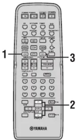

When performing this operation with the remote control, first press TUNER to set the remote to tuner mode.
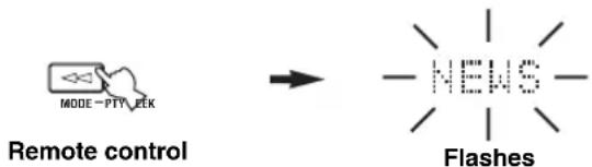
1 Press PTY SEEK MODE on the remote control to set this unit in the PTY SEEK mode.
The program type of the station being received or "NEWS" flashes in the front panel display. To exit from the PTY SEEK mode, press PTY SEEK MODE again.
flowchart
graph LR
    A["MODE - PTY_EEK"] --> B["→"]
    B --> C["NEWS"]
    C --> D["Flashes"]
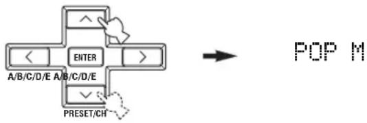
2 Press PRESET/CH ∧ / ∨ on the remote control to select the desired program type.
The selected program type appears in the front panel display.
flowchart
graph TD
    A["ENTER"] --> B["A/B/C/D/E"]
    B --> C["A/B/C/D/E"]
    C --> D["PRESET/CH"]
    D --> E["POP M"]
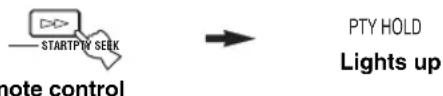
3 Press PTY SEEK START on the remote control to begin searching all preset Radio Data System stations.
The selected program type flashes and the PTY HOLD indicator lights up in the front panel display while searching for stations.
To cancel searching, press PTY SEEK START again.
flowchart
graph LR
    A["STARTPTV SEEK"] --> B["PTY HOLD"]
    B --> C["Lights up"]
- The unit stops searching when it finds a station broadcasting the selected type of program.
- If the found station is not the one you desire, press PTY SEEK START again. This unit resumes searching for another station broadcasting the same type of program.
EON function
This function uses the EON data service on the Radio Data System station network. If you select the desired program type (NEWS, INFO, AFFAIRS or SPORT), this unit automatically searches for all preset Radio Data System stations that are scheduled to broadcast the selected type of program and switches from the station currently being received to the new station when the broadcast starts.
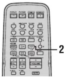

When performing this operation with the remote control, first press TUNER to set the remote to tuner mode.
Note
This function can only be used when a Radio Data System station that offers the EON data service is being received. When such a station is being received, the EON indicator lights up in the front panel display.
1 Check that the EON indicator is lit in the front panel display.
If the EON indicator is not lit up, tune into another Radio Data System station so that the EON indicator lights up.
2 Press EON repeatedly on the remote control to select the desired program type (NEWS, INFO, AFFAIRS or SPORT).
The selected program type name appears in the front panel display.

Remote control
- If a preset Radio Data System station type starts broadcasting the selected type of program, the unit automatically switches from the program being received to that program. (The EON indicator flashes.)
- When broadcasting of the selected program ends, the unit returns to the previous station (or another program on the same station).
■To cancel this function
Press EON repeatedly until no program type name is shown in the front panel display.
ADVANCED SETUP
■ADVANCED SETUP menu parameters
Change the initial settings (indicated in bold under each parameter) to reflect the needs of your listening environment.
Factory presets PRESET
Use to reset all parameters to the factory presets.
Choices: CANCEL, RESET
- Select CANCEL if you do not want the parameters of this unit to be initialized when you reset the factory presets.
- Select RESET if you want all of the parameters of this unit to be initialized when you reset the factory presets.
Notes
- This setting does not affect the parameters in the ADVANCED SETUP menu.
- The resetting process starts next time you turn on the power of this unit.
Remote REMOTE
Use to switch the remote control ID of this unit.
Choices: ID1, ID2
- Select ID1 to operate this unit using an alternative code.
- Select ID2 to operate this unit using the default code.
Note
You must also make settings for the remote control (see page 30).
Tuner TU
(Asia and General models only)
Use to switch the frequency step selection according to the frequency spacing in your area.
Choices: AM10/FM100, AM9/FM50
• North, Central and South America: AM10/FM100 (kHz)
• Other areas: AM9/FM50 (kHz)
Changing the ADVANCED SETUP menu parameters
The ADVANCED SETUP menu is displayed in the front panel display.
[Symbol]
- During the ADVANCED SETUP procedure, audio output is muted.
- During the ADVANCED SETUP procedure, only MASTER ON/OFF, A/B/C/D/E and the preset station number buttons (1 and 2) on the front panel are operational.
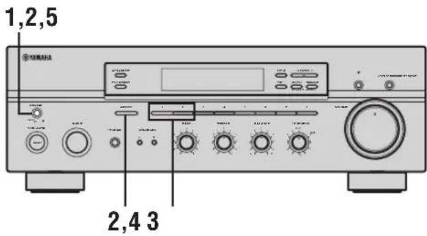
1 Press MASTER ON/OFF on the front panel to release it outward to the OFF position.
![YAMAHA RX497 - [Symbol] - 2](/content/2026/04/618721/images/db227fcaf9f4c51603afe3801501c174547f0510e9751bc531447b47dd239489.jpg)
2 Press and hold A/B/C/D/E on the front panel and then press MASTER ON/OFF inward to the ON position.
The power of this unit is turned on, and the ADVANCED SETUP menu appears in the front panel display.
![YAMAHA RX497 - [Symbol] - 3](/content/2026/04/618721/images/7f4d0b49a9bcdd624796932ac8c89fae450862bad1085af455a1220065a405c7.jpg)
While holding down, press
![YAMAHA RX497 - [Symbol] - 4](/content/2026/04/618721/images/453412558cdbb6e01cd026502912379b3df834f61a3ade30561e2bbc1970a6e2.jpg)
3 Press the preset station number buttons (1 and 2) on the front panel repeatedly to move through the menu and select the parameter you want to adjust.
See page 29 for a complete list of available parameters.
![YAMAHA RX497 - [Symbol] - 5](/content/2026/04/618721/images/4e03becf06556b05816e5322ba357a201fba1521366543fa027a0f3841022482.jpg)
4 Press A/B/C/D/E on the front panel repeatedly to toggle between the available parameters.
![YAMAHA RX497 - [Symbol] - 6](/content/2026/04/618721/images/c1934552e4cae3a779d48283c1f2103f1bf699fe0281032a74dacecfd24b9e96.jpg)
5 Press MASTER ON/OFF to release it outward to the OFF position to confirm your setting.
![YAMAHA RX497 - [Symbol] - 7](/content/2026/04/618721/images/9fbd500fb1ff9c2855ddbb5104ba4291681088ff0ad0a031f45d6fb7d511f95f.jpg)
Note
The settings you made are reflected next time you turn on the power of this unit.
Switching the remote control ID
You can select the unit you want to operate with the remote control by switching the remote control ID.
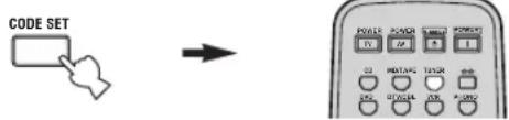
1 Press and hold CODE SET on the remote control and then press TUNER on the remote control.
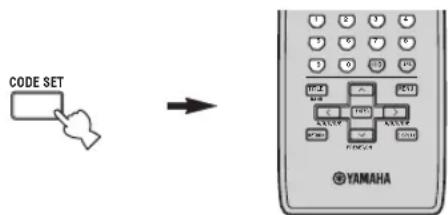
2 While holding down CODE SET on the remote control, use the numeric buttons on the remote control to enter the three-digit code number listed in the table below.
| Remote control ID* (this unit's setting) | Function Code number |
| ID1 | To operate this unit using an alternative code. |
| ID2 (default setting) | To operate this unit using the default code. |
* When you change the remote control ID, you must switch the remote control ID of this unit (see page 29).
When using multiple YAMAHA receivers or amplifiers with the same default code setting, you may unwantedly operate those components simultaneously. In this case, set one of the alternative codes for this unit to operate this unit separately.
ZONE 2
Connecting the Zone 2 components
This unit allows you to configure a multi-room audio and video system. The Zone 2 feature enables you to set this unit to reproduce separate input sources in the main room and in Zone 2 (the second room) simultaneously. You can also control this unit from the second room using the Zone 2 remote control (sold separately).
You need the following additional equipment to use the multi-room system of this unit:
- Zone 2 remote control
- An infrared signal receiver for the second room
- An infrared emitter for the main room. This emitter transmits the infrared signals sent by the Zone 2 remote control in Zone 2 to the components in the main room.
- An amplifier and speakers for the second room

Some YAMAHA models are able to connect directly to the REMOTE OUT jack on the rear panel of this unit. If you own these products, you may not need to use an infrared emitter. Up to six YAMAHA components can be connected as shown below.

flowchart
graph LR
    A["Infrared signal receiver"] -->|IN| B["This unit"]
    B -->|IN| C["YAMAHA component"]
    C -->|OUT| D["YAMAHA component"]
    D -->|IN| C
    C -->|OUT| E["Output"]
    style A fill:#fff,stroke:#000
    style B fill:#ccc,stroke:#000
    style C fill:#ccc,stroke:#000
    style D fill:#ccc,stroke:#000
■Multi-room configuration and connections
The following illustration shows an example of the multi-room system configuration and connections.
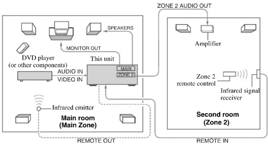
flowchart
graph TD
    A["Main Room (Main Zone)"] --> B["Main Room (Main Zone)"]
    B --> C["Video In"]
    C --> D["Monitor Out"]
    D --> E["Speaker"]
    E --> F["This Unit"]
    F --> G["Main"]
    F --> H["ZONE 2"]
    I["DVD player (or other components)"] --> J["AUDIO IN"]
    J --> K["VIDEO IN"]
    L["Infrared emitter"] --> M["Remote OUT"]
    N["ZONE 2 AUDIO OUT"] --> O["Amplifier"]
    P["Second Room (Zone 2)"] --> Q["Remote IN"]
    R["Infrared signal receiver"] --> S["Remote IN"]
    T["SPEAKERS"] --> D
    U["Ground"] --> V["Ground"]

Since there are many possible ways to connect and use this unit in a multi-room configuration, we recommend that you consult with your nearest authorized YAMAHA dealer or service center for the Zone 2 connections that best meet your requirements.
Controlling Zone 2
You can control the input source of Zone 2 independently of the listening conditions in the main room.
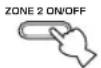
1 Press ZONE 2 ON/OFF on the front panel to turn on Zone 2.
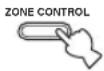
2 Press ZONE 2 CONTROL on the front panel
The ZONE 2 indicator flashes in the front panel display.
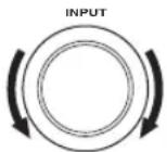
3 While the ZONE 2 indicator is flashing, rotate the INPUT selector on the front panel to select the input source of Zone 2.

- You can also select the input source by using the Zone 2 remote control (sold separately). Press POWER on the Zone 2 remote control to turn on Zone 2, and then press one of the input selector buttons to select the input source.
- You can mute the sound output to Zone 2 by pressing MUTE on the ZONE 2 remote control. Press again to restore the sound output.
REMOTE CONTROL FEATURES
Control area
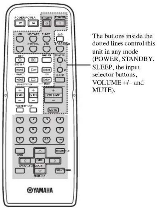
■Controlling this unit
The shaded areas below can be used to control this unit.
■Controlling other components
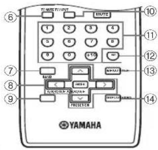
The shaded areas below can be used to control other audio and video components made by YAMAHA and other manufacturers. Each button has a different function depending on the selected component. Select the component you want to control by pressing one of the input selector buttons. The name of the selected component appears in the front panel display.
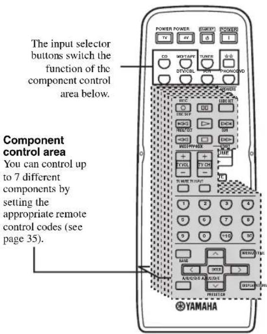

You can use the ☆ button to control other components regardless of whether they are connected to this unit.
Controlling other components
In addition to controlling this unit, you can also control other audio and video components made by YAMAHA and other manufacturers using the supplied remote control. To control other components, you must set the appropriate remote control codes.
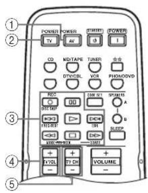

| DVD player VCR | Digital TV/Cable TV | TV CD player Tape deck | MD recorder | Tuner | ||||
| 1 AV POWER | Power *1 | Power *1 | Power *1 | VCR power | Power *1 | Power *1 | Power *1 | Power *1 |
| 2 TV POWER | TV power TV power | TV power | Power *1 | TV power TV power | TV power TV power | |||
| 3 ◀◀ | Search backward | Search backward | VCR search backward | VCR search backward | Search backward | Search backward | Search backward | PTY MODE *2 |
| ▷▷Search forward | Search forward | VCR search forward | VCR search forward | Search forward | Search forward | Search forward | PTY START *2 | |
| ◀◀ | Skip backward | Skip backward | Direction A | Skip backward | FREQ/TEXT *2 | |||
| ▶▶ | Skip forward | Skip forward | Direction B | Skip forward | EON *2 | |||
| REC/DISC SKIP | Disc skip | Rec | VCR rec | VCR rec | Disc skip | Rec | Rec | |
| □ | Stop | Stop | VCR stop | VCR stop | Stop | Stop | Stop | |
| □□ | Pause | Pause | VCR pause | VCR pause | Pause | Deck A/B | Pause | |
| ▷ | Play | Play | VCR play | VCR play | Play | Play | Play | |
| 4 TV VOL + | TV volume + | TV volume + | TV volume + | Volume + | TV volume + | TV volume + | TV volume + | TV volume + |
| TV VOL - | TV volume - | TV volume - | TV volume - | Volume - | TV volume - | TV volume - | TV volume - | TV volume - |
| 5 TV CII + | TV channel + | Channel + | Channel + | Channel + | TV channel + | TV channel + | TV channel + | TV channel + |
| TV CII - | TV channel - | Channel - | Channel - | Channel - | TV channel - | TV channel - | TV channel - | TV channel - |
| 6 TV MUTE | TV mute | TV mute | TV mute | Mute | TV mute | TV mute | TV mute | TV mute |
| 7 TITLE | Title | Title | Title | Title | Band | |||
| 8 ENTER | Menu enter | Menu select | Menu select | |||||
| PRESET/CH^ | Menu up | Menu up | Menu up | Preset up(1 to 8) | ||||
| PRESET/CII ∨ | Menu down | Menu down | Menu down | Preset down(1 to 8) | ||||
| A/B/C/D/E < | Menu left | Menu left | Menu left | Preset down(A to E) | ||||
| A/B/C/D/E > | Menu right | Menu right | Menu right | Preset up(A to E) | ||||
| 9 RETURN | Return | Return | Return | Return | ||||
| 10 TV INPUT | TV input | TV input | TV input | Input | TV input | TV input | TV input | TV input |
| 11 1-9, 0, +10 | Numeric buttons | Numeric buttons | Numeric buttons | Numeric buttons | Numeric buttons | Numeric buttons | Preset stations (1-8) | |
| 12 ENT. | Enter | Enter/rccall | Enter/numeric button | Index | ||||
| 13 MENU | Menu | Menu | Menu | |||||
| 14 DISPLAY | Display | Display | Display | Display | Display | |||
*1 This button functions only when the original remote control of the component has the POWER button.
*2 These buttons function for Europe model only.
Setting remote control codes
You can control other components by setting the appropriate remote control codes. Codes can be set up for each input source. For a complete list of available remote control codes, refer to "LIST OF REMOTE CONTROL CODES" at the end of this manual.
The following table show the default component category (library) and the remote control code for each input source.
Remote control code default settings
| Input source | Default component category (library) | Manufacturer | Default YAMAHA code |
| CD CD Y | AMAHA 199 | ||
| MD/TAPE TAPE YAMAHA 499 | |||
| DVD DVD | YAMAHA 699 | ||
| DTV/CBL* | — | — | — |
| VCR | — | — | — |
| PHONO | — | — | — |
| ☆☆ | — | — | — |
* You can only set the TV remote control codes for the DTV/CBL button. However, other remote control codes can be set for any input selector buttons except DTV/CBL.
Note
You may not be able to operate your other YAMAHA components even if the YAMAHA remote control code is initially set as listed above. In this case, try setting other YAMAHA remote control codes.
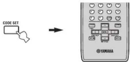
1 Press and hold CODE SET on the remote control and then press one of the input selector buttons on the remote control to select the input source you want to set up.
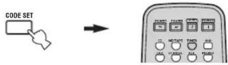
Note
You must press and hold CODE SET throughout this operation.
2 While holding down CODE SET on the remote control, use the numeric buttons on the remote control to enter the three-digit remote control code for the selected input source.
When the setting succeeds, "PRESET OK" appears; however, when it does not, "PRESET NG" appears in the front panel display.
To reset the code, enter the default code for each input source listed in the remote control code default settings table.
Notes
- If the manufacturer of your component has more than one code, try setting each of them until you find the correct one.
- You can only assign one remote control code to each input selector button.
TROUBLESHOOTING
Refer to the chart below if this unit does not function properly. If the problem you are experiencing is not listed below or if the instructions below do not help, set this unit to the standby mode, disconnect the power cord, and contact the nearest authorized YAMAHA dealer or service center.
■General
| Problem Cause | Remedy | See page | |
| This unit fails to turn on. | The power supply cord is not connected or the plug is not completely inserted. | Connect the power supply cord firmly. | — |
| The impedance setting is incorrect. Set the impedance to match your speakers. | 11 | ||
| The protection circuitry has been activated because of a short circuit, etc. | Check that the speaker wires are not touching each other and then turn the power of this unit back on. | 11 | |
| The IMPEDANCE SELECTOR switch on the rear panel is not set to either end. | Set the IMPEDANCE SELECTOR switch to either end when the power of this unit is turned off. | 11 | |
| This unit has been exposed to a strong external electric shock (such as lightning or strong static electricity). | Set this unit to the standby mode, disconnect the power supply cord, plug it back in after 30 seconds, then use it normally. | — | |
| No sound Incorrect input or output cable connections. | Connect the cables properly. If the problem persists, the cables may be defective. | 10 | |
| Select an appropriate input source with the INPUT selector on the front panel (or one of the input selector buttons on the remote control). | 15 | ||
| Turn on the corresponding SPEAKERS A or SPEAKERS B. | 15 | ||
| Speaker connections are not secure. Secure the connections. | 11 | ||
| The sound suddenly goes off. | The protection circuitry has been activated because of a short circuit, etc. | Check that the IMPEDANCE SELECTOR setting is correct. | 11 |
| Check that the speaker wires are not touching each other and then turn the power of this unit back on. | 11 | ||
| Only the speaker on one side can be heard. | Incorrect cable connections. Connect the cables properly. If the problem persists, the cables may be defective. | 10 | |
| Incorrect setting for the BALANCE control. | Set the BALANCE control to the appropriate position. | 16 | |
| There is a lack of bass and no ambience. | The + and - wires are connected in reverse at the amplifier or the speakers. | Connect the speaker wires to the correct + and - phase. | 11 |
| A “humming” sound can be heard. | Incorrect cable connections. Connect the audio plugs firmly. If the problem persists, the cables may be defective. | 10 | |
| No connection from the turntable to the GND terminal. | Make the GND connection between the turntable and this unit. | 10 | |
| The volume level is low while playing a record. | The record is being played on a turntable with an MC cartridge. | The turntable should be connected to this unit through the MC head amplifier. | — |
| The volume level cannot be increased, or the sound is distorted. | The component connected to the MD/TAPE OUT jacks of this unit is turned off. | Turn on the power of the component. | — |
| The sound is degraded when listening with the headphones connected to the CD player or the tape deck connected to this unit. | The power of this unit is turned off, or this unit is set to the standby mode. | Turn on the power of this unit. | 14 |
| The sound level is low. | The LOUDNESS control is functioning. Set | the LOUDNESS control to the FLAT position. | 16 |
| Using the BASS, TREBLE, BALANCE and LOUDNESS controls does not affect the tonal quality. | The PURE DIRECT button is turned on. The | PURE DIRECT button must be turned off to use those controls. | 16 |
Tuner
| Problem Cause | Remedy | See page | ||
| FM | FM stereo reception is noisy. | The particular characteristics of the FM stereo broadcasts being received may cause this problem when the transmitter is too far away or the antenna input is poor. | Check the antenna connections.Try using a high-quality directional FM antenna. | 12 |
| Try using the manual tuning method. | 21 | |||
| There is distortion, and clear reception cannot be obtained even with a good FM antenna. | There is multipath interference. Adjust the antenna position to eliminate the multipath interference. | — | ||
| The desired station cannot be tuned in with the automatic tuning method. | The signal is too weak. Try using a high-quality directional FM antenna. | 12 | ||
| Try using the manual tuning method. | 21 | |||
| Previously preset stations can no longer be tuned in. | This unit has been disconnected for a long period. | Preset the stations again. | 22 | |
| AM | The desired station cannot be tuned in with the automatic tuning method. | The signal is weak or the antenna connections are loose. | Tighten the AM loop antenna connections and orient it for the best reception. | — |
| Try using the manual tuning method. | 21 | |||
| There are continuous crackling and hissing noises. | The noises may result from lightning, fluorescent lamps, motors, thermostats or other electrical equipment. | Try using an outdoor antenna and a ground wire.This will help somewhat, but it is difficult to eliminate all noise. | — | |
| There are buzzing and whining noises. | A TV set is being used nearby. Move this unit away from the TV set. | — | ||
■Remote control
| Problem Cause | Remedy | See page | |
| The remote control does not work nor function properly. | Wrong distance or angle. The remote control | will function within a maximum range of 6 m (19.7 ft) and no more than 30 degrees off-axis from the front panel. | 9 |
| Direct sunlight or lighting (from an inverter type of fluorescent lamp, etc.) is striking the remote control sensor of this unit. | Reposition this unit. | — | |
| The batteries are weak. Replace all batteries. | 9 | ||
| The remote control ID and this unit's ID do not match. | Switch the remote control ID or this unit's ID. | 29, 30 | |
| The remote control code was not correctly set. | Try setting another code of the same manufacturer using “LIST OF REMOTE CONTROL CODES” at the end of this manual. | 35 | |
| Even if the remote control code is correctly set, there are some models that do not respond to the remote control. | Use the supplied remote control for the components. | — |
SPECIFICATIONS
AUDIO SECTION
- Minimum RMS Output Power (8 Ω, 20 Hz to 20 kHz, 0.04% THD) .... 75 W + 75 W
• Dynamic Power (IHF) (8/6/4/2 Ω) 105/125/150/178 W
• Maximum Output Power [Europe model only] (1 kHz, 0.7% THD, 4 Ω) 105 W
- IEC Output Power [Europe model only] (1 kHz, 0.04% THD, 8 Ω) 84 W
• Power Band Width (0.08% THD, 35 W, 8 Ω) 10 Hz to 50 kHz
- Damping Factor (SPEAKERS A) 20 Hz to 20 kHz, 8 Ω .... 150 or more
• Maximum Output Power (EIAJ) [Asia and General models only] (1 kHz, 10% THD, 8 Ω) .... 115 W
• Maximum Input Signal PHONO (1 kHz, 0.04% THD) .... 70 mV or more CD, etc. (1 kHz, 0.04% THD) .... 2.2 V or more
- Frequency Response CD, etc. (20 Hz to 20 kHz) .... 0 ± 0.5 dB CD, etc. PURE DIRECT ON (10 Hz to 100 kHz) .... 0 ± 1.0 dB
- RIAA Equalization Deviation PHONO .... ± 0.5 dB
- Total Harmonic Distortion PHONO to OUT (REC) (20 Hz to 20 kHz, 3 V) .... 0.02% or less CD, etc. to SPEAKERS (20 Hz to 20 kHz, 35 W, 8 Ω) .... 0.02% or less
- Signal to Noise Ratio (IHF-A Network) PHONO (5 mV input shorted) .... 82 dB or more CD, etc. (185 mV input shorted) .... 108 dB or more
- Residual Noise (IHF-A Network) PURE DIRECT ON 100 μV
- Gain Tracking Error (0 to -60 dB) 2 dB or less
- Input Sensitivity/Input Impedance PHONO .... 3.0 mV/47 kΩ CD, etc. .... 185 mV/47 kΩ
- Output Level/Output Impedance OUT (REC) 185 mV/1.2 kΩ or less SUB WOOFER OUTPUT 4 V/1.2 kΩ or less ZONE 2 OUT 185 mV/1.2 kΩ or less
- Headphone Output/Impedance (Input 1 kHz, 185 mV, 8 Ω, 0.015% THD) CD, etc. 0.47 V/390 Ω
- Channel Separation CD, etc. (5.1 kΩ input shorted, 1/10 kHz) ...... 65/50 dB or more
- Tone Control Characteristics BASS Boost/Cut (20 Hz) ....±10 dB Turnover Frequency ....350 Hz TREBLE Boost/Cut (20 kHz) ....±10 dB Turnover Frequency ....3.5 kHz
- Continuous Loudness Control Attenuation (1 kHz) ....-30 dB
VIDEO SECTION
- Video Signal Type [U.S.A., Canada and General models] .... NTSC [Other models] .... PAL
- Signal to Noise Ratio 50 dB or more
- Frequency Response (MONITOR OUT) Composite .... 5 Hz to 10 MHz, -3 dB
FM SECTION
- Tuning Range [U.S.A. and Canada models] .... 87.5 to 107.9 MHz [Asia and General models] .... 87.5/87.50 to 107.9/108.00 MHz [Other models] .... 87.50 to 108.00 MHz
- Usable Sensitivity (IHF).... 1.0 μV (11.2 dBf)
- Signal to Noise Ratio (IHF) Mono/Stereo 76 dB/70 dB
• Harmonic Distortion (1 kHz) Mono/Stereo 0.2%/0.3%
- Stereo Separation (1 kHz) 45 dB
• Frequency Response .... 20 Hz to 15 kHz, +0.5/-2 dB
AM SECTION
- Tuning Range [U.S.A. and Canada models] .... 530 to 1710 kHz [Asia and General models] .... 530/531 to 1710/1611 kHz [Other models] .... 531 to 1611 kHz
- Usable Sensitivity 300 V/m
GENERAL
• Power Supply [U.S.A. and Canada models] ..... AC 120 V, 60 Hz [Asia model] ..... AC 220/230-240 V, 50/60 Hz [General model] ..... AC 110/120/220/230-240 V, 50/60 Hz [Australia model] ..... AC 240 V, 50 Hz [Europe model] ..... AC 230 V, 50 Hz
• Power Consumption 180 W
- Standby Power Consumption 0.1 W
• Maximum Power Consumption [General model only] (8 Ω, 1 kHz, 10% THD) 400 W
- A C Outlets [Australia model] .... 1 (Total 100 W maximum) [General model] .... 2 (Total 50 W maximum) [Other models] .... 2 (Total 100 W maximum)
- Dimensions (W x H x D) 435 x 151 x 308 mm (17-1/8" x 5-15/16" x 12-1/8")
- Weight 8.7 kg (19 lbs. 3 oz.)
* Specifications are subject to change without notice.
ATTENTION: VEUILLEZ LIRE CE QUI SUIT AVANT D'UTILISER L'APPAREIL.
ACCESSOIRES FOURNIS....2
COMMANDES ET FONCTIONS.... 3
Face avant .... 3
Service PTY SEEK.... 27
Service EON 28
OPÉRATIONS DÉTAILLÉES
RÉGLAGES APPROFONDIS....29
③Prise SUB WOOFER OUTPUT
natural_image
Diagram of a medical or laboratory procedure showing three cylindrical objects connected by a wire, with an arrow pointing to one (no text or symbols present)flowchart
graph TD
    A["Screen with monitor icon"] --> B["Shelf with internal components"]
    B --> C["Shelf with base component"]
    C --> D["Shelf with cable and connector"]
    D --> E["Shelf with base component"]
    E --> F["Shelf with cable and connector"]
natural_image
Line drawing of a cable being inserted into a two-hole cabinet (no text or symbols)natural_image
Simple line drawing of a hand inserting a cable into a two-hole cabinet (no text or symbols)natural_image
Simple line drawing of a computer monitor with arrows indicating rotation or move (no text or symbols)Remarques
Remarques
■EON (Enhanced Other Networks)
③SUB WOOFER OUTPUT-Buchse
natural_image
Diagram of three cylindrical objects with a connecting rod, no text or symbols presentRot: positiv (+) Schwarz: negativ (−)
natural_image
Line drawing of a hand inserting a cable into a double door (no text or symbols)natural_image
Line drawing of a hand inserting a device into a two-hole drawer (no text or symbols)natural_image
Simple line drawing of a computer monitor with curved arrows indicating rotation (no text or symbols)Hinweise
Hinweis
③SUB WOOFER OUTPUT-koppling
1 Öppna luckan till batterifacket.
2 Skruva loss knoppen.
natural_image
Diagram of three cylindrical objects with a connecting rod, no text or symbols presentflowchart
graph TD
    A["Display Panel"] --> B["Computer Monitor"]
    B --> C["Printer"]
    C --> D["Printer with Press"]
    D --> E["Printer with Cable"]
natural_image
Line drawing of a cable inserted into a double door with a connector (no text or symbols)4 Släpp upp tabben.
natural_image
Line drawing of a hand inserting a card into a folder (no text or symbols)natural_image
Simple line drawing of a computer monitor with curved arrows indicating rotation or data flow (no text or symbols)Anmärkningar
flowchart
graph LR
    A["SLEEP"] --> B["→ SLEEP 120 min → SLEEP 90 min"]
    B --> C["SLEEP OFF ← SLEEP 30 min ← SLEEP 60 min"]
■EON (Enhanced Other Networks)
flowchart
graph LR
    A["STARTPY SEEK"] --> B["PTY HOLD Tänds"]
Anmärkning
WEERGAVE EN OPNAME 15
natural_image
Diagram of a medical device with three cylindrical components and a catheter inserted (no text or symbols)natural_image
Line drawing of a cable inserted into a double door with a pointer, showing electrical connection (no text or symbols)natural_image
Simple line drawing of a cabinet with two doors and a hand inserting a cable (no text or symbols)natural_image
Simple line drawing of a computer monitor with curved arrows indicating rotation or navigation (no text or symbols)Opmerkingen
Opmerking
natural_image
Diagram of a medical or laboratory procedure showing three cylindrical objects with a catheter inserted (no text or labels)flowchart
graph TD
    A["Screen with monitor icon"] --> B["Shelf with internal components"]
    B --> C["Shelf with base component"]
    C --> D["Base with arrow indicating assembly"]
natural_image
Line drawing of a cable being inserted into a two-hole electrical socket (no text or symbols)4 Опустите защелку.
natural_image
Simple line drawing of a hand inserting a card into a double door (no text or symbols)natural_image
Simple line drawing of a computer monitor with arrows indicating rotation or move (no text or symbols)Примечания
Примечание
JC Penny 293, 297, 234, 237
JVC 296, 246, 247, 286
Kendo 298
KTV 297, 239
Loewe 298, 248
LXI 293, 297, 225,
226, 233
Magnavox 297, 225, 239
Marantz 298
Matsui 295
Memorex 297
Mitsubishi 299, 297, 259, 287
NEC 297,252,282
Nokia 244, 245
Nokia Oceanic 245
Nordmende 265, 266
Onwa 296
Panasonic 234, 235, 236,
253, 288, 211
Philco 297, 225, 239
Philips 225, 298
Pioneer 226, 235, 254,
255, 268
Portland 297, 256
Proscan 293
Proton 297
Quasar 234, 235
Radio Shack 299, 293, 297
RCA 293, 297, 234,
256, 257, 258
SABA 223, 269, 265, 266
Sampo 297
Samsung 297, 239, 248,
262, 275
Sanyo 295, 233, 279,
272, 273, 274, 212
Schneider 296
Scott 297
Sharp 292, 239, 232,
213, 216
Siemens 229
Signature 292
Sony 263, 214
Sylvania 297, 225
Telefunken 269, 264, 265, 266
Thomson 223, 266
Toshiba 292, 226, 267, 215
Videch 297, 242
Wards 297, 239, 232
Yamaha 299, 292, 253, 242
VCR
Admiral 395
Aiwa 396, 397, 398, 329
Akai 322, 323, 324
Audio Dynamic 392, 394
Bell&Howell 393
Blaupunkt 325, 326
Brocsonic 327
Bush 322
Canon 325,328
CGM 396,332
Citizen 396
Craig 396, 363
Curtis Mathis 397, 328, 333
Daewoo 328, 334, 335
DBX 392,394
Dimensia 333
Dynatech 397
Emerson 327,334,396,397
Fisher 393,336
Funai 397
GE 328,333,387
Go Video 353
LG/Goldstar 396,388
Goodmans 334, 337
Grundig 332, 338
Hitachi 325, 333, 349,
342, 343
Instant Replay 325, 328
Itt/Nokia 393
JC Penny 392, 393, 394,
328, 333, 349,
396, 363
JVC 392, 394, 344,
345, 346, 347
Kendo 396
Kenwood 392, 394, 396
Loewe 396, 337
Luxor 395
LXI 393, 396, 397,
336, 349
Magnavox 325, 326, 328
Marantz 392, 394
Marta 396
Matsui 396
Memorex 328, 336, 396, 397
Minolta 333, 349
Mitsubishi 399, 344, 348,
359, 353
MTC 363, 397
Multitech 397, 348, 354
NEC 392, 394, 344, 383
Nokia 393,395
Nokia Oceanic 395
Okano 323
Olympic 325, 328
Orion 327
Panasonic 325, 328, 355,
378, 384, 385, 386
Pentax 333, 349
Philco 325, 328, 397
Philips 325, 326, 328,
337, 356, 357
Phonola 337
Pilot 396
Pioneer 325
Quasar 325, 328
RCA/PROSCAN 325, 326,
328, 333, 335,
349, 358, 363, 397
Realistic 393, 397, 328,
336, 359, 396, 363
Samsung 354, 358, 363,
364, 366
Sansui 394
Sanyo 393, 336, 367
Schneider 337
Scott 399, 335, 336,
348, 359, 354, 358
Seleco 322
Sharp 395,382
Siemens 393
Signature 2000 395, 397
Sony 368, 379, 372,
373, 374, 375
Sylvania 397, 325, 326, 328
Symphonic 397
Tandberg 334
Tandy 397
Tashiro 396
Tatung 392, 394
Teac 392, 394, 397
Technics 325.328
Teknika 396
Telefunken 376, 377
Thomas 397
Thorn 393,396
Toshiba 335,389
Totevison 363, 396
Unitech 363
Universum 396, 327, 376
Videosonic 363
W.WHouse 396
Wards 395, 396, 336
Yamaha 399, 392, 393, 394
Zenith 344, 368, 379,
396, 397
DVD player
DENON 623, 624
Funai 625
HITACHI 626
JVC 627
KENWOOD 628
Mitsubishi 629
Onkyo 632, 633, 634
Panasonic 623, 635
Philips 699, 647
Pioneer 636, 637, 638
RCA 639
Samsung 642
Sharp 643
Sony 644
Toshiba 634
LG/GOLD STAR 645
THOMSON 646
Yamaha 699, 622, 623
CD player
Yamaha 199
CD recorder
Yamaha 499
MD recorder
Yamaha 599
Tape deck
Yamaha 799

YAMAHA
© 2005 YAMAHA CORPORATION All rights reserved.
ATTENZIONE: LEGGERE QUANTO SEGUE PRIMA DI UTILZZARE L'UNITÀ.
③Presa SUB WOOFER OUTPUT
natural_image
Diagram of three cylindrical mechanical components with a connecting rod (no text or symbols)flowchart
graph TD
    A["Screen with monitor icon"] --> B["Device with internal structure"]
    B --> C["Device with internal structure and top panel"]
    C --> D["Base with arrow pointing to component"]
natural_image
Line drawing of a cable being inserted into a double door (no text or symbols)natural_image
Simple line drawing of a hand inserting a device into a box (no text or symbols)natural_image
Simple line drawing of a computer monitor with curved arrows indicating rotation (no text or symbols)Note

- Potenza dinamica (IHF) (8/6/4/2 Ω) 105/125/150/178 W
Modelo general ..... 110/120/220/230–240 V CA, 50/60 Hz
Modelo de Asia 220/230–240 V CA, 50/60 Hz
ADVERTENCIA
PARA REDUCIR EL RIESGO DE INCENDIO O DESCARGA ELÉCTRICA, NO EXPONGA ESTA UNIDAD A LA LLUVIA NI A LA HUMEDAD.
Control Zone 2....32
FUNCIONES DEL MANDO A DISTANCIA ....33
Área de control 33
③Jack SUB WOOFER OUTPUT
flowchart
graph TD
    A["TV digital"] --> B["Video"]
    C["Reproductor DVD"] --> D["Video"]
    E["Videograbadora"] --> F["Video"]
    G["Altavoces A"] --> H["Audio"]
    I["Altavoces B"] --> J["Audio"]
    K["Audio"] --> L["Audio"]
    M["Audio"] --> N["Audio"]
    O["Audio"] --> P["Audio"]
    Q["Audio"] --> R["Audio"]
    S["Audio"] --> T["Audio"]
    U["Audio"] --> V["Audio"]
    W["Audio"] --> X["Audio"]
    Y["Audio"] --> Z["Audio"]
    AA["Audio"] --> AB["Audio"]
    AC["Audio"] --> AD["Audio"]
    AE["Audio"] --> AF["Audio"]
    AG["Audio"] --> AH["Audio"]
    AI["Audio"] --> AJ["Audio"]
    AK["Audio"] --> AL["Audio"]
    AM["Audio"] --> AN["Audio"]
    AO["Audio"] --> AP["Audio"]
    AQ["Audio"] --> AR["Audio"]
    AS["Audio"] --> AT["Audio"]
    AU["Audio"] --> AV["Audio"]
    AW["Audio"] --> AX["Audio"]
    AY["Reproductor CD"] --> AZ["Giradiscos"]
    BA["Radio"] --> BB["Radio"]
    BC["Radio"] --> BD["Radio"]
    BE["Radio"] --> BF["Radio"]
    BG["Radio"] --> BH["Radio"]
    BI["Radio"] --> BJ["Radio"]
    BK["Radio"] --> BL["Radio"]
    BM["Radio"] --> BN["Radio"]
    BO["Radio"] --> BP["Radio"]
    BQ["Audio"] --> BR["Audio"]
    BS["Audio"] --> BT["Audio"]
    BU["Audio"] --> BV["Audio"]
    BW["Audio"] --> BX["Audio"]
    BY["Audio"] --> BZ["Audio"]
    CA["Audio"] --> CB["Audio"]
    CC["Audio"] --> CD["Audio"]
    CE["Audio"] --> DD["Audio"]
    DE["Audio"] --> DF["Audio"]
    DG["Audio"] --> DH["Audio"]
    DI["Audio"] --> DJ["Audio"]
    DK["Audio"] --> DL["Audio"]
    DM["Audio"] --> DN["Audio"]
    DO["Audio"] --> DX["Audio"]
    DY["Audio"] --> DY["Audio"]
    DY["Audio"] --> DYA["Audio"]
    DYA["Audio"] --> DYB["Audio"]
    DYB["Audio"] --> DYC["Audio"]
    DYC["Audio"] --> DYD["Audio"]
    DYD["Audio"] --> DYE["Audio"]
    DYE["Audio"] --> DYF["Audio"]
    DYF["Audio"] --> DYG["Audio"]
    DYG["Audio"] --> DYH["Audio"]
    DYH["Audio"] --> DYI["Audio"]
    DYI["Audio"] --> DYJ["Audio"]
    DYJ["Audio"] --> DYK["Audio"]
    DYK["Audio"] --> DYL["Audio"]
    DYL["Audio"] --> DYM["Audio"]
    DYM["Audio"] --> DYN["Audio"]
    DYN["Audio"] --> DYO["Audio"]
    DYO["Audio"] --> DYP["Audio"]
    DYP["Audio"] --> DYQ["Audio"]
    DYQ["Audio"] --> DYR["Audio"]
    DYR["Audio"] --> DYS["Audio"]
    DYS["Audio"] --> DYT["Audio"]
    DYT["Audio"] --> DYU["Audio"]
    DYU["Audio"] --> DYV["Audio"]
    DYV["Audio"] --> DYW["Audio"]
    DYW["Audio"] --> DYX["Audio"]
    DYX["Audio"] --> DYY["Audio"]
    DYY["Audio"] --> DYZ["Audio"]
natural_image
Diagram of a mechanical component with three cylindrical parts and a connecting rod (no text or symbols)flowchart
graph TD
    A["Component placement"] --> B["Assembly"]
    B --> C["Final assembly with a bracket and load"]
2 Mantenga pulsada la lengüeta.
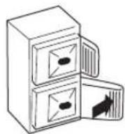
natural_image
Line drawing of a cable inserted into a double door with a pointer (no text or symbols)natural_image
Simple line drawing of a hand inserting a cable into a two-hole cabinet (no text or symbols)natural_image
Simple line drawing of a computer monitor with curved arrows indicating rotation or movement (no text or symbols)Notas
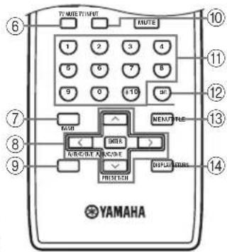
JC Penny 293, 297, 234, 237
JVC 296,246,247,286
Kendo 298
KTV 297, 239
Loewe 298, 248
LXI 293, 297, 225.
226,233
Magnavox 297, 225, 239
Marantz 298
Matsui 295
Memorex 297
Mitsubishi 299, 297, 259, 287
NEC 297, 252, 282
Nokia 244,245
Nokia Oceanic 245
Nordmende 265,266
Onwa 296
Panasonic 234, 235, 236,
253, 288, 211
Philco 297, 225, 239
Philips 225, 298
| Pioneer | 226, 235, 254, 255, 268 |
| Portland | 297, 256 |
| Proscan | 293 |
| Proton | 297 |
| Quasar | 234, 235 |
| Radio Shack | 299, 293, 297 |
| RCA 293, 297, 234, 256, 257, 258 | |
| SABA | 223, 269, 265, 266 |
| Sampo | 297 |
| Samsung | 297, 239, 248, 262, 275 |
| Sanyo | 295, 233, 279, 272, 273, 274, 212 |
| Schneider | 296 |
| Scott 297 | |
| Sharp | 292, 239, 232, 213, 216 |
| Siemens | 229 |
| Signature | 292 |
| Sony 263, 214 | |
| Sylvania 297, 225 | |
| Telefunken | 269, 264, 265, 266 |
| Thomson | 223, 266 |
| Toshiba | 292, 226, 267, 215 |
| Videch | 297, 242 |
| Wards 297, 239, 232 | |
| Yamaha | 299, 292, 253, 242 |
VCR
Admiral 395
Aiwa 396, 397, 398, 329
Akai 322, 323, 324
Audio Dynamic 392, 394
Bell&Howell 393
Blaupunkt 325, 326
Brocsonic 327
Bush 322
Canon 325,328
CGM 396,332
Citizen 396
Craig 396, 363
Curtis Mathis 397, 328, 333
Daewoo 328, 334, 335
DBX 392,394
Dimensia 333
Dynatech 397
Emerson 327,334,396,397
Fisher 393.336
Funai 397
GE 328,333,387
Go Video 353
LG/Goldstar 396,388
Goodmans 334,337
Grundig 332, 338
Hitachi 325, 333, 349,
342, 343
Instant Replay 325, 328
Itt/Nokia 393
| JC Penny | 392, 393, 394, |
| 328, 333, 349, | |
| 396, 363 | |
| JVC | 392, 394, 344, |
| 345, 346, 347 | |
| Kendo | 396 |
| Kenwood | 392, 394, 396 |
| Locwe 396, 337 | |
| Luxor | 395 |
| LXI 393, 396, 397, | |
| 336, 349 | |
| Magnavox | 325, 326, 328 |
| Marantz 392, 394 | |
| Marta | 396 |
| Matsui | 396 |
| Memorex | 328, 336, 396, 397 |
| Minolta | 333, 349 |
| Mitsubishi | 399, 344, 348, |
| 359, 353 | |
| MTC 363, 397 | |
| Multitech | 397, 348, 354 |
| NEC | 392, 394, 344, 383 |
| Nokia | 393, 395 |
| Nokia Oceanic | 395 |
| Okano | 323 |
| Olympic 325, 328 | |
| Orion | 327 |
| Panasonic 325, 328, 355, | |
| 378, 384, 385, 386 | |
| Pentax 333, 349 | |
| Philco 325, 328, 397 | |
| Philips | 325, 326, 328, |
| 337, 356, 357 | |
| Phonola | 337 |
| Pilot | 396 |
| Pioneer | 325 |
| Quasar | 325, 328 |
| RCA/PROSCAN | 325, 326, |
| 328, 333, 335, | |
| 349, 358, 363, 397 | |
| Realistic 393, 397, 328, | |
| 336, 359, 396, 363 | |
| Samsung | 354, 358, 363, |
| 364, 366 | |
| Sansui | 394 |
| Sanyo | 393, 336, 367 |
| Schneider | 337 |
| Scott 399, 335, 336, | |
| 348, 359, 354, 358 | |
| Seleco | 322 |
| Sharp | 395, 382 |
| Siemens | 393 |
| Signature 2000 | 395, 397 |
| Sony 368, 379, 372, | |
| 373, 374, 375 | |
| Sylvania | 397, 325, 326, 328 |
| Symphonic | 397 |
| Tandberg | 334 |
| Tandy | 397 |
| Tashiro | 396 |
| Tatung | 392, 394 |
| Teac | 392, 394, 397 |
| Technics | 325, 328 |
| Teknika | 396 |
| Telcfunken | 376, 377 |
| Thomas | 397 |
| Thorn | 393, 396 |
| Toshiba | 335, 389 |
| Totevison | 363, 396 |
| Unitech | 363 |
| Universum | 396, 327, 376 |
| Videosonic | 363 |
| W.WHousc | 396 |
| Wards 395, 396, 336 | |
| Yamaha | 399, 392, 393, 394 |
| Zenith | 344, 368, 379, 396, 397 |
DVD player
DENON 623, 624
Funai 625
HITACHI 626
JVC 627
KENWOOD 628
Mitsubishi 629
Onkyo 632, 633, 634
Panasonic 623, 635
Philips 699,647
Pioneer 636,637,638
RCA 639
Samsung 642
Sharp 643
Sony 644
Toshiba 634
LG/GOLD STAR 645
THOMSON 646
Yamaha 699,622,623
CD player
Yamaha 199
CD recorder
Yamaha 499
MD recorder
Yamaha 599
Tape deck
Yamaha 799


natural_image
Pure geometric diagram with intersecting lines and circular shapes (no text or symbols)
YAMAHA
© 2005 YAMAHA CORPORATION All rights reserved.
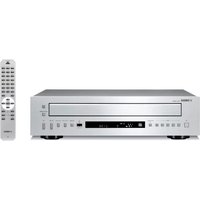
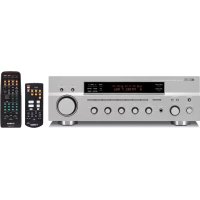
- WARNING
- CONTENTS
- INTRODUCTION
- PREPARATION
- BASIC OPERATION
- ADVANCED OPERATION
- ADDITIONAL INFORMATION
- FEATURES
- Built-in 2-channel power amplifier
- Sophisticated AM/FM tuner
- Other features
- SUPPLIED ACCESSORIES
- CONTROLS AND FUNCTIONS
- Front panel
- ①MASTER ON/OFF
- Note
- Memory back-up
- ②MAIN ZONE ON/OFF
- Notes
- ③ZONE 2 ON/OFF
- ④ZONE CONTROL
- ⑤ Remote control sensor
- ⑥Front panel display
- ⑦EDIT
- ⑧FM/AM
- ⑨TUNING ◀/▶
- ⑩TUNING MODE
- ⑪MEMORY
- ⑫PURE DIRECT and indicator
- ⑬MD/TAPE MONITOR
- ⑭VOLUME
- ⑮INPUT selector
- ⑯A/B/C/D/E
- ⑰PHONES jack
- ⑱SPEAKERS A/B
- ⑲BASS
- ⑳TREBLE
- ②1BALANCE
- ⑳LOUDNESS
- ②3Preset station number buttons
- (1 to 8)
- Front panel display
- ①SP (SPEAKERS) A/B indicators
- ②ZONE 2 indicator
- ③Input source indicators
- ④MD/TAPE MON (MONITOR) indicator
- ⑤MEMORY indicator
- ⑥AUTO indicator
- ⑦STEREO indicator
- ⑧SLEEP indicator
- ⑨MUTE indicator
- ⑩Multi-information display
- ⑪ TUNED indicator
- ■Europe model only
- ⑫Radio Data System indicators
- PTY HOLD indicator
- EON indicator
- Rear panel
- ■Asia and General models only
- Remote control
- Installing batteries in the remote control
- ■Notes on batteries
- Using the remote control
- ■Handling the remote control
- CONNECTIONS
- CAUTION
- Connecting speakers
- ■IMPEDANCE SELECTOR
- Connecting the AM and FM antennas
- ■Connecting the AM loop antenna
- Connecting the power supply cord
- ■AC OUTLET(S) (SWITCHED)
- Turning on and off this unit
- Press MASTER ON/OFF on the front panel inward to the ON position to turn on the power of this unit.
- #
- PLAYING AND RECORDING
- Playing a source
- Adjusting the tonal quality
- ■Adjusting the BALANCE control
- ■Using the PURE DIRECT button
- ■Adjusting the BASS and TREBLE controls
- BASS
- TREBLE
- ■Adjusting the LOUDNESS control
- Rotate the LOUDNESS control on the front panel to the FLAT position.
- Rotate VOLUME on the front panel (or press VOLUME +/- on the remote control) to set the sound output level to the loudest listening level that you would listen to.
- Rotate the LOUDNESS control until the desired volume is obtained.
- Recording a source
- Using the sleep timer
- Muting the sound output
- Press MUTE on the remote control to mute the sound output.
- Press MUTE on the remote control again to resume the sound output.
- FM/AM TUNING
- Automatic tuning
- Manual tuning
- Automatic preset tuning
- Rotate the INPUT selector (or press TUNER on the remote control) to select TUNER.
- Press FM/AM on the front panel to select FM as the reception band.
- Press and hold MEMORY on the front panel for more than 3 seconds.
- Press TUNING ◀/▷ once to begin automatic preset tuning.
- ■Customized automatic preset tuning
- Press and hold MEMORY on the front panel for more than 3 seconds.
- Press A/B/C/D/E and then press one of the preset station number buttons on the front panel to select the preset station group and the preset station number where the first received station will be stored.
- Press TUNING ◀/▷ on the front panel to begin automatic preset tuning.
- Manual preset tuning
- Selecting preset stations
- Exchanging preset stations
- RADIO DATA SYSTEM (EUROPE MODEL ONLY)
- Receiving Radio Data System stations
- ■PS (Program Service name) mode
- ■PTY (Program Type) mode
- ■RT (Radio Text) mode
- ■CT (Clock Time) mode
- ■EON (Enhanced Other Networks)
- Changing the Radio Data System mode
- PTY SEEK function
- Press PTY SEEK MODE on the remote control to set this unit in the PTY SEEK mode.
- Press PRESET/CH ∧ / ∨ on the remote control to select the desired program type.
- Press PTY SEEK START on the remote control to begin searching all preset Radio Data System stations.
- EON function
- Check that the EON indicator is lit in the front panel display.
- Press EON repeatedly on the remote control to select the desired program type (NEWS, INFO, AFFAIRS or SPORT).
- ■To cancel this function
- ADVANCED SETUP
- ■ADVANCED SETUP menu parameters
- Factory presets PRESET
- Remote REMOTE
- Tuner TU
- (Asia and General models only)
- Changing the ADVANCED SETUP menu parameters
- [Symbol]
- Switching the remote control ID
- ZONE 2
- Connecting the Zone 2 components
- ■Multi-room configuration and connections
- Controlling Zone 2
- REMOTE CONTROL FEATURES
- Control area
- ■Controlling this unit
- ■Controlling other components
- Controlling other components
- Setting remote control codes
- TROUBLESHOOTING
- SPECIFICATIONS
- AUDIO SECTION
- VIDEO SECTION
- FM SECTION
- AM SECTION
- GENERAL
- ATTENTION: VEUILLEZ LIRE CE QUI SUIT AVANT D'UTILISER L'APPAREIL.
- OPÉRATIONS DÉTAILLÉES
- Remarques
- Hinweise
- Hinweis
- Anmärkningar
- Anmärkning
- Opmerkingen
- Opmerking
- Примечания
- Примечание
- VCR
- DVD player
- CD player
- CD recorder
- MD recorder
- Tape deck
- YAMAHA
- ATTENZIONE: LEGGERE QUANTO SEGUE PRIMA DI UTILZZARE L'UNITÀ.
- ADVERTENCIA
- Notas
Brand : YAMAHA
Model : RX497
Category : Audio System