TV 900 - Measuring equipment Testboy - Free user manual and instructions
Find the device manual for free TV 900 Testboy in PDF.
| Product type | EVSE adapter for testing charging stations |
| Brand | Testboy |
| Model | TV 900 |
| Category | Measuring equipment |
| Power supply | Via type 2 connector (power from the charging station) |
| Main functions | Simulation of charge states (CP-State A to D), simulation of cable current (PP-State: N.C., 13A, 20A, 32A, 63A), phase test L1/L2/L3, fault simulation (PE break, CP short circuit), continuity test |
| Display | Phase indicator LED |
| Connectors | Type 2 connector, 4 banana jacks (L1, L2, L3, N, PE, CP), BNC connector for oscilloscope, mains socket 5A max |
| Selectors | Rotary CP-State (6 positions), rotary PP-State (5 positions), rotary Phase (L1/L2/L3) |
| Buttons | CP-State E (fault simulation), PE (fault simulation) |
| Operating temperature | 0 to +40 °C |
| Protection class | IP40 |
| Socket load limit | 5 A |
| Cleaning | Damp cloth with mild detergent; do not allow moisture to enter |
| Safety | Use by qualified electricians; observe the 5 safety rules; do not use in humid environments |
| Compliance | CE |
| Estimated weight | Approximately 300 g |
| Estimated dimensions | 150 x 80 x 50 mm |
| Warranty | Voids if instructions are not followed |
| Manufacturer | Testboy GmbH, Germany |
Frequently Asked Questions - TV 900 Testboy
User questions about TV 900 Testboy
0 question about this device. Answer the ones you know or ask your own.
Ask a new question about this device
Download the instructions for your Measuring equipment in PDF format for free! Find your manual TV 900 - Testboy and take your electronic device back in hand. On this page are published all the documents necessary for the use of your device. TV 900 by Testboy.
USER MANUAL TV 900 Testboy
natural_image
Line drawing of a handheld electronic device with control panel and buttons (no text or symbols)Testboy® TV 900
Version 1.1

Testboy TV 900 3
Bedienungsanleitung

Testboy TV 900 9
Operating Manual

Testboy TV 900 15
PP-State explanation 13
CP-State explanation 13
Fault simulation 13
Cleaning 13
Technical data 14
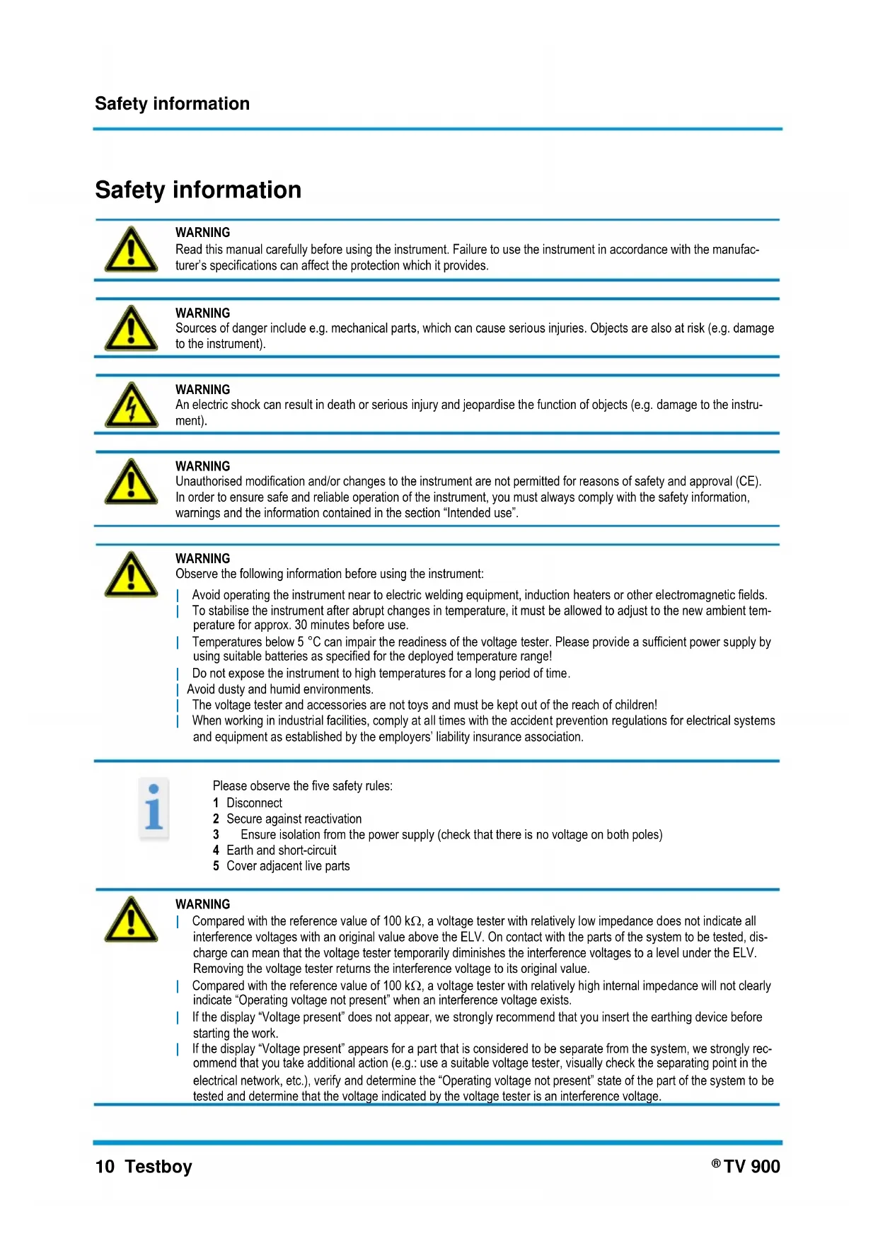
Safety information

WARNING
Read this manual carefully before using the instrument. Failure to use the instrument in accordance with the manufacturer's specifications can affect the protection which it provides.

WARNING
Sources of danger include e.g. mechanical parts, which can cause serious injuries. Objects are also at risk (e.g. damage to the instrument).
WARNING
An electric shock can result in death or serious injury and jeopardise the function of objects (e.g. damage to the instrument).

WARNING
Unauthorised modification and/or changes to the instrument are not permitted for reasons of safety and approval (CE). In order to ensure safe and reliable operation of the instrument, you must always comply with the safety information, warnings and the information contained in the section "Intended use".

WARNING
Observe the following information before using the instrument:
Avoid operating the instrument near to electric welding equipment, induction heaters or other electromagnetic fields.
To stabilise the instrument after abrupt changes in temperature, it must be allowed to adjust to the new ambient temperature for approx. 30 minutes before use.
Temperatures below 5 °C can impair the readiness of the voltage tester. Please provide a sufficient power supply by using suitable batteries as specified for the deployed temperature range!
Do not expose the instrument to high temperatures for a long period of time.
Avoid dusty and humid environments.
The voltage tester and accessories are not toys and must be kept out of the reach of children!
When working in industrial facilities, comply at all times with the accident prevention regulations for electrical systems and equipment as established by the employers' liability insurance association.

Please observe the five safety rules:
1 Disconnect
2 Secure against reactivation
3 Ensure isolation from the power supply (check that there is no voltage on both poles)
4 Earth and short-circuit
5 Cover adjacent live parts

WARNING
Compared with the reference value of 100 kΩ, a voltage tester with relatively low impedance does not indicate all interference voltages with an original value above the ELV. On contact with the parts of the system to be tested, discharge can mean that the voltage tester temporarily diminishes the interference voltages to a level under the ELV. Removing the voltage tester returns the interference voltage to its original value.
Compared with the reference value of 100 kΩ, a voltage tester with relatively high internal impedance will not clearly indicate "Operating voltage not present" when an interference voltage exists.
If the display "Voltage present" does not appear, we strongly recommend that you insert the earthing device before starting the work.
If the display “Voltage present” appears for a part that is considered to be separate from the system, we strongly recommend that you take additional action (e.g.: use a suitable voltage tester, visually check the separating point in the electrical network, etc.), verify and determine the “Operating voltage not present” state of the part of the system to be tested and determine that the voltage indicated by the voltage tester is an interference voltage.
Intended use
Only intended for use by qualified electricians and specialized personnel.
The instrument is only intended for the applications described in the manual, such as AC, DC and continuity checks, phase and rotating field tests. Any other usage is forbidden and can result in accidents or destruction of the instrument. Any such misapplication will result in the immediate expiry of all guarantee and warranty claims on the part of the operator against the manufacturer. All users of this tester should have the appropriate training and be familiar with the dangers associated with performing a voltage test that occur in an industrial environment, the necessary safety precautions and the procedure for checking the correct function of the instrument before and after each use.

We shall not accept any liability for damage to property or injury to persons resulting from improper handling or non-compliance with the safety information. In such cases, any warranty claim becomes invalid. An exclamation mark in a triangle indicates safety information in the operating manual. Read the entire manual before commissioning. This instrument is CE-approved and thus fulfils the required directives.
We reserve the right to change specifications without prior notice © 2020 Testboy GmbH, Germany.
Disclaimer

The warranty claim is voided in cases of damage caused by failure to comply with the specifications of the manual!
We shall not accept any liability for the resulting damage!
Testboy does not accept responsibility for damage resulting from
Failure to observe the manual
Changes to the product which have not been approved by Testboy or
Spare parts which have not been manufactured or approved by Testboy
The consumption of alcohol, drugs or medicines.
Correctness of the operating manual
This operating manual has been compiled with considerable care and attention. No guarantee is given that the data, figures and drawings are complete or correct. Subject to changes, printing mistakes and errors.
Disposal
Dear Testboy customer, Purchasing our product gives you the option of returning the instrument at the end of its lifespan to suitable collection points for waste electrical equipment.

The WEEE directive regulates the return and recycling of electrical appliances. Manufacturers of electrical appliances are obliged to take back and recycle all sold electrical appliances free of charge. Electrical appliances may no longer be disposed of through conventional waste disposal channels. Electrical appliances must be recycled and disposed of separately. All equipment subject to this directive is marked with this logo.
Certificate of quality
All quality-related activities and processes performed by Testboy GmbH are subject to continual monitoring within the framework of a Quality Management System. Testboy GmbH confirms that the testing equipment and instruments used during the calibration process are subject to a continual monitoring process.
Declaration of conformity
The product conforms to the most recent directives. For further information, go to www.testboy.de
Operation
Thank you for deciding on the Testboy® TV 900, an EVSE (Electric Vehicle Supply Equipment) adapter.
This test adapter is an accessory for additional Testboy measuring instruments and testers, for example, to carry out safety or function tests using an installation tester. It has a type 2 connector for testing charge accessories for electric vehicles (EVSE Mode 3).
The solid housing of the Testboy® TV 900 means that it can also be used under harsh operating conditions.
The Testboy TV 900's LED display is intended as a guide value rather than a reading.
For this, suitable measuring/test equipment should be used!
Safety information
You have chosen an instrument providing a high degree of safety. To ensure safe and correct application, it is necessary to fully read this operating manual before using the instrument for the first time.
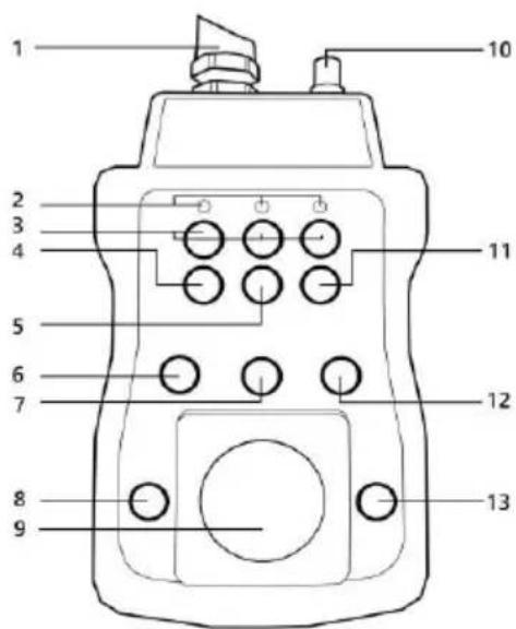
1) Type 2 connector
2) Phase indicator
3) Banana jacks for phases L1, L2, L3
4) Banana jack for CP
5) Banana jack for PE
6) CP-State rotary switch
7) Phase rotary switch
8) CP-State E (Fault Simulation) button
9) Socket
10) BNC jack
11) Banana jack for N
12) PP-State rotary switch
13) PE Fault Simulation button
The following safety precautions apply:
If the display fails to indicate one or more functions, then do not continue to use the instrument. It must be checked by a specialist.
Avoid contact with the banana jacks (3, 4, 5, 11)! (Refer to the figure)
The instrument must not be operated in a humid environment!
Always keep the instrument dry and clean. The housing should only be cleaned using a damp cloth.
The various signals displayed by the voltage tester should not be used for measurement purposes.
text_image
1 2 3 4 5 6 7 8 9 10 11 12 13Function
The instrument simulates a connected electric vehicle and enables various charge states to be simulated. The TV 900 has various measuring and tapping points. To switch on the instrument, connect the type 2 connector to a charge column. When the charge column is enabled, the LEDs indicate the phase(s). The "CP-State" (Control Pilot Resistance) rotary switch can be used to simulate various charge states. The banana jacks enable testing using various test leads. The BNC jack enables an oscilloscope to be used. Additional measuring instruments can be connected to the socket. The phases can be switched with the relevant rotary switch. The "PP-State" (Proximity Pilot Resistance) switch can be used to simulate a cable (N.C., 13 A, 20 A, 32 A, 63 A are selectable).
The "CP-State E" and "PE Fault Simulation" buttons can be used to simulate fault states. E.g. a PE conductor break.

WARNING
The socket has a maximum load capacity of 5 A! It is also important not to switch between phases under load!
Test procedure
Connect your installation tester to the socket (alternatively to the banana jacks) on the TV 900.
Select CP-State "A" and PP-State "N.C.".
Then connect the type 2 connector for the TV 900 to the charge equipment/column to be tested.
Installation tests can only be carried out for voltage-free installation circuits.
Now simulate the various charge conditions with the CP-State and PP-State rotary switches. Observe the feedback from the charge equipment/column.
The “Phase” rotary switch can be used to switch the phases to the sockets, so that each phase can be tested individually via the socket. Via the BNC jack on the head piece of the instrument, an oscilloscope can also be connected.
PP-State explanation
| Position | Description |
| N.C. | Incorrect operation or connector not connected |
| 13 A | |
| 20 A | Setting for maximum current of EV cable |
| 32 A | TV 900 is connected to the charge equipment/column and can carry out testing in each of these settings. |
| 63 A |
CP-State explanation
| Position | Simulation | Description |
| A | Charge equipment/column is not connected | TV 900 is idle, charge equipment/column does not supply energy |
| B | Charge equipment/column is connected | TV 900 has been detected, charge equipment/column does not supply energy |
| C | Charge equipment/column is active without fan | Charge equipment/column is ready for charging, TV 900 starts the charge process and does not require ventilation, energy supply only if there is no ventilation. |
| D | Charge equipment/column is active with fan | Charge equipment/column is ready for charging, TV 900 starts charge process and requires ventilation, energy supply only if there is no ventilation. |
Fault simulation
The TV 900 test adapter has the option to simulate two faults that could occur on charge columns.
CP-State E can be activated with the switch on the left of the socket. This corresponds to a fault or a break in the communication between the vehicle and the charge column. A short circuit is switched via a diode between PE and CP. This sometimes trips the fuse of the charging station!
The button on the right of the socket can be used to interrupt the PE conductor. It is then possible to check whether the charge column responds accordingly to this fault.
Cleaning
Use a damp cloth and mild household detergent to clean the instrument should it become soiled through daily use. Never use harsh cleaning agents or solvents to clean the instrument.

To avoid electric shocks, do not allow moisture to penetrate the housing.
Technical data
| Display | LEDs |
| Operating temperature | 0 to +40 °C |
| Protection class | IP 40 |
| Voltage supply | Type 2 connector / charge equipment/column for electric vehicles |
| Socket load limit | 5 A |
Table des matières
text_image
Testboy® GmbH, Germany Stands For Quality Since 1953Testboy GmbH Tel: +49 4441 89112-10
Germany info@testboy.de