
Whaly - Vacuum Cleaner HAYWARD - Free user manual and instructions
Find the device manual for free Whaly HAYWARD in PDF.

| Brand | Hayward |
| Model | Whaly |
| Product type | Above-ground pool vacuum cleaner with turbine suction |
| Category | Pool vacuum |
| Use | Automatic cleaning of above-ground pools |
| Power source | Connection to the pool's filtration system (pump) |
| Dimensions (approx.) | 40 x 40 x 30 cm |
| Weight (approx.) | 5 kg |
| Material | Reinforced plastic |
| Color | Blue/gray (as shown) |
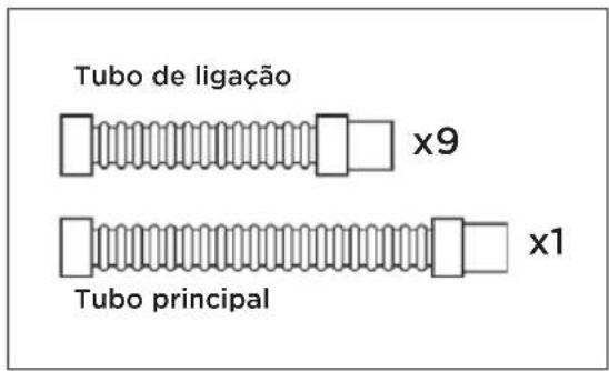
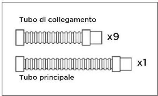
| Number of hose lengths | Variable depending on installation (starting hose + 2 additional recommended) |
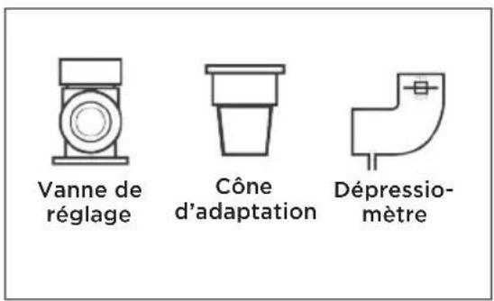
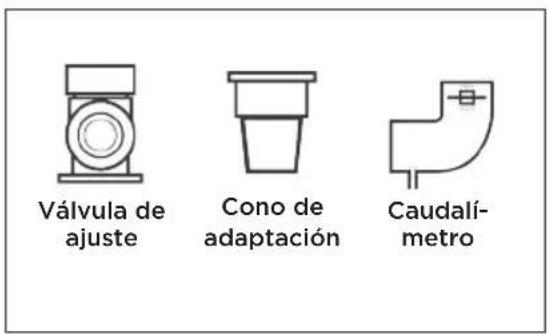
| Included accessories | Main hose, skimmer adapter cone, flow meter, adjustment valve (optional) |
| Main function | Cleaning of floor and walls by suction |
| Movement mechanism | Turbine driven by water flow |
| Recommended water flow | Between MIN and MAX marks on flow meter |
| Routine maintenance | Cleaning filters, checking skids and wings, storing hose flat |
| Wear parts | Skids, wings, flaps |
| Warranty | 2 years against manufacturing defects (excluding wear parts) |
| Safety standards | Do not use in the presence of children, remove before chemical treatment |
| Country of origin | United States (Hayward brand) |
Frequently Asked Questions - Whaly HAYWARD
User questions about Whaly HAYWARD
0 question about this device. Answer the ones you know or ask your own.
Ask a new question about this device
Download the instructions for your Vacuum Cleaner in PDF format for free! Find your manual Whaly - HAYWARD and take your electronic device back in hand. On this page are published all the documents necessary for the use of your device. Whaly by HAYWARD.
USER MANUAL Whaly HAYWARD
natural_image
Simple line drawing of an open book with no text or symbols visible
HAYWARD®
ROBOTS HORS SOL
Robot à aspiration
natural_image
Line drawing of a mechanical component with a lever and textured body (no text or symbols)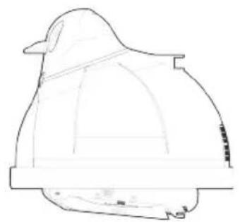
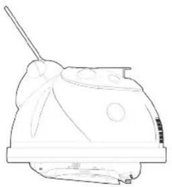
natural_image
Line drawing of a helmet with no text or symbols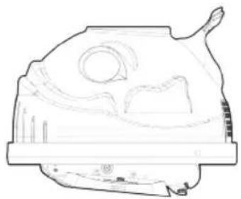
natural_image
Line drawing of a ceramic vessel with decorative patterns and a handle (no text or symbols)

natural_image
Simple line icon of an open book (no text or symbols)natural_image
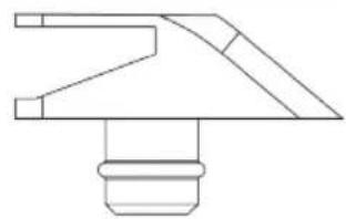
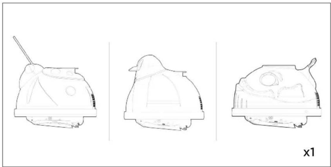
Three technical line drawings of a mechanical component, showing different views (top, front, side) with no visible text or symbols.Nettoyeur

Tuyau de connexion/ Tuyau principal
natural_image
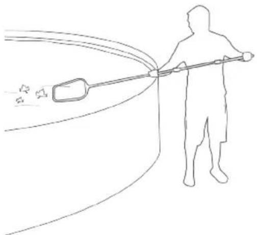
Line drawing of a person spraying water with a long tool, no text or symbols presentDÉBRIS
natural_image
Three identical black test tubes with liquid, no text or symbols present
pH : 7,2 à 7,6
natural_image
Diagram showing two hands holding a small object with bidirectional arrows indicating movement or force (no text or symbols)Étape 1
flowchart
graph TD
    A["Bottom Component"] --> B["Stage 1st"]
    B --> C["Stage 2nd"]
    C --> D["Output"]
Étape 2
Étape 7

OFF

natural_image
Prohibition sign showing a helmet crossed out by a diagonal line, no text or symbols present
natural_image
Line drawing of a mechanical component with a threaded top and base, no text or symbols presentÉtape 8

ON
CONSEILS IMPORTANTS

natural_image
Circular diagram with concentric rings and a diagonal line crossing through the center (no text or symbols)
natural_image
Illustration showing a hand holding a helmet and a circular diagram of a hand using a spring, with no text or symbols present.


natural_image
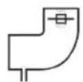
Simple line drawing of a container with a pipe and a circular symbol indicating no prohibition (no text or labels)CONSEILS DE MAINTENANCE
natural_image
Pure mechanical component diagram without any text, numbers, or symbolsSEMELLE EN BON ÉTAT
natural_image
Pure technical line drawing of a mechanical component without any text, numbers, or symbolsSEMELLE USÉE

natural_image
Line drawing of a device with labeled parts and a close-up of hands holding a connector (no text or symbols present)CONSEILS DE MAINTENANCE
natural_image
Technical line drawing of a curved mechanical component with directional arrows indicating movement or force (no text or symbols)Étape 3

natural_image
Illustration of a curved mechanical component with a triangular base and a triangular load, no text or symbols present.Étape 4

natural_image
Technical line drawing of a Hayward industrial machine component with no visible text or symbolsSuction Pool Cleaner
Owner's Manual
natural_image
Line drawing of a mechanical component with a lever and textured body (no text or symbols)
natural_image
Line drawing of a helmet with no text or symbols
natural_image
Line drawing of a ceramic vessel with decorative patterns and a handle (no text or symbols)

natural_image
Simple line icon of an open book (no text or symbols)TURBINE SUCTION CLEANER
Owner's Manual
Congratulations on the purchase of your Hayward automatic suction pool cleaning system. Your cleaner is the smart, efficient way to clean your above-ground pool.
Hayward turbine cleaners are powered by your pool's filter system and are designed to work well with most systems. The performance of the cleaner in your pool will be relative to its power source. Because the operation and performance of the cleaner are system reliant, there is a remote possibility that a service call may be necessary to complete the proper installation of your cleaner. This call will be at the consumer's expense.
Lastly, one or more of the accessories designed for the cleaner, including additional hose sections, might be applicable to your installation. Consult your Hayward dealer for prices and availability.
FOR YOUR RECORDS
Purchase Date:
Serial Number:
SAFETY WARNINGS
DO NOT use to remove large debris in new pools or when dewinterizing.
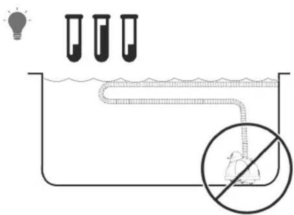
REMOVE cleaner and hose before adding ANY chemicals to your pool.
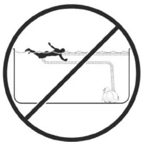
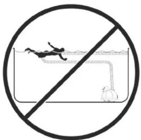
DO NOT swim with cleaner.
Store the cleaner in a shaded, safe area.
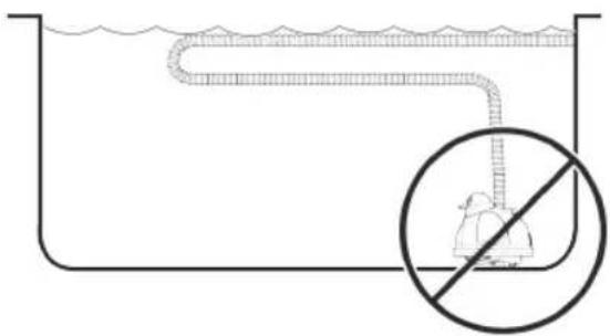
Hoses must be stored straight. DO NOT coil the hose.
THIS IS NOT A TOY. Do not use in the presence of children.
KEEP AWAY from children and pets.
REMOVE cleaner when performing backwash.
REMEMBER safety first.
KEY

Tip

Attention
Pressure Adjustment
Pump
natural_image
Three technical line drawings of a mechanical component, showing different views (top, front, side) with no visible text or symbols.Pool Cleaner
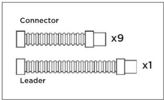
Connector/Leader Hoses Accessory Kit
PREPARING THE POOL
Please complete the following steps to prepare your pool for installation:
natural_image
Line drawing of a person cleaning a surface with a long-handled tool, no text or symbols presentDEBRIS
Remove any large objects and excessive debris from the pool.
WATER LEVEL
Confirm that water level is at the recommended level.
natural_image
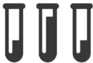
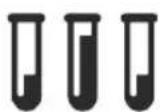
Three identical black test tubes with liquid, no text or symbols present
pH: 7.2 - 7.6
Chlorine: 1.0-3.0 PPM
Total Alkalinity: 80 - 120 PPM
WATER CHEMISTRY
Make sure water is properly balanced and that the pool is free from algae.
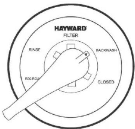
FILTER
Clean or backwash the filter.
Clean the skimmer and pump baskets prior to installing the cleaner.
Sizing Suction Hose
natural_image
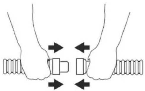
Diagram showing two hands holding a small object with bidirectional arrows indicating movement or force (no text or symbols)Step 1
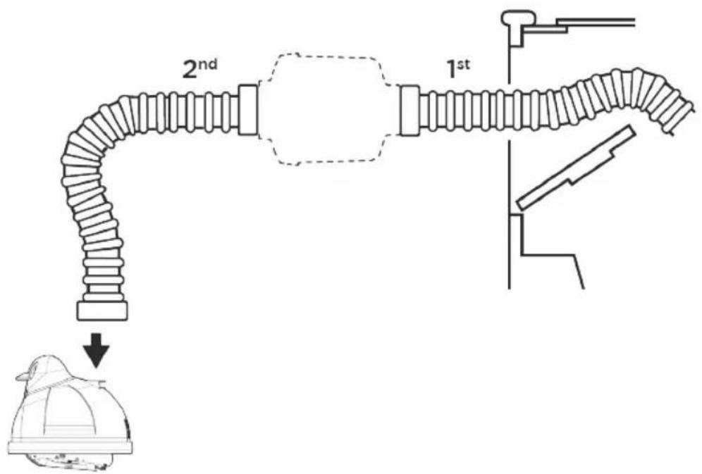
Connect hose sections.
Note: Make sure all connections are tight to prevent air leaks.

TIP: Wetting the hose ends will make it easier to connect the hose sections.

If optional leaf canister is purchased, install between 1st and 2nd hose sections starting from the wall connector or skimmer.
flowchart
graph TD
    A["Base"] --> B["Stage 1st"]
    B --> C["Stage 2nd"]
    C --> D["Final State"]
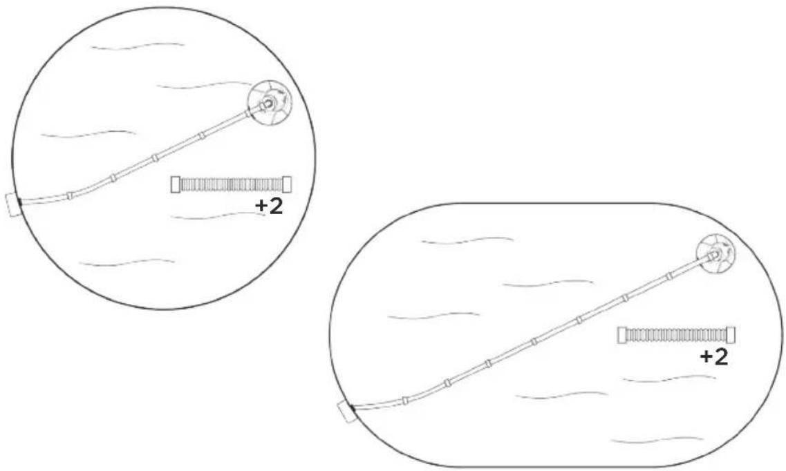
Step 2
Pull hose to farthest location in the pool opposite the wall connector or skimmer + 2 extra hose sections.
Step 3


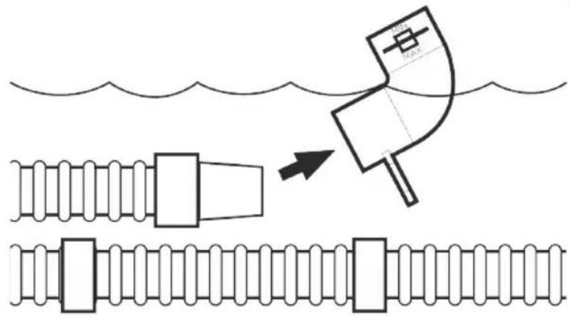
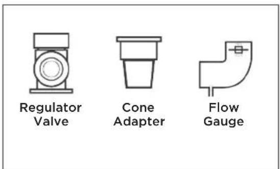
Fill hose completely with water. Insert flow gauge onto the leader hose. Attach the C-clip of the gauge onto the 1st hose section.
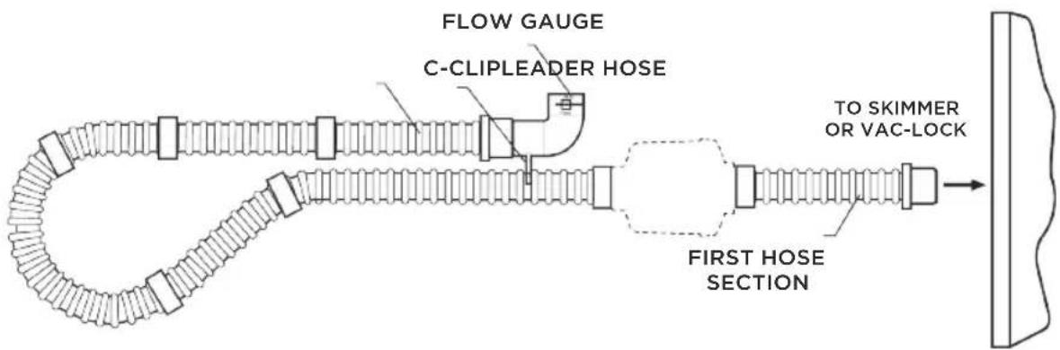

Make sure the flow gauge is under water.
INSTALLATION
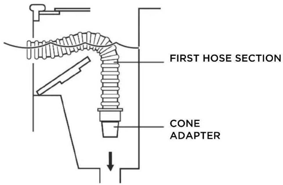
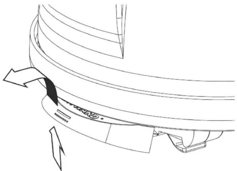
Step 4
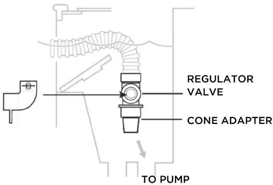
Connecting to skimmer:
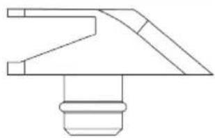
Connect the skimmer cone adapter to tapered male end of the first hose section.
Note: Hose end goes into cone adapter.

ON
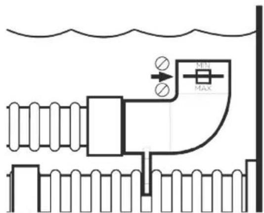
Step 5
Check the water flow reading on the flow gauge.
The black disk should be between the "MIN" and "MAX" markings.
If the disk is in the proper location, move on to step 6.
Reading Too High?

If the black disk is outside of the box on the "MAX" side and you have connected your hose to the skimmer, reduce the vacuum/water flow by using one of the following:
- Suction valve(s) in the filter system (if equipped with)
• Hayward regulator valve
To install the Hayward regulator valve:

OFF
- Remove the hose from the skimmer cone adapter.
- Close the regulator valve by rotating the blue collar clockwise until tight.
- Insert the regulator valve onto the skimmer cone adapter and the hose end into the regulator valve.
- Turn the filter system on and allow it to evacuate any air in the system.
- Turn the blue collar counterclockwise until black disk appears between "MIN" and "MAX" markings.
INSTALLATION
Reading Too Low?

An initial vacuum reading that is TOO low to meet the water flow setting necessary to operate the cleaner is indicative of a system problem, and not a problem with the cleaner.
The regulator valve cannot be used to INCREASE the initial vacuum reading.
Step 6
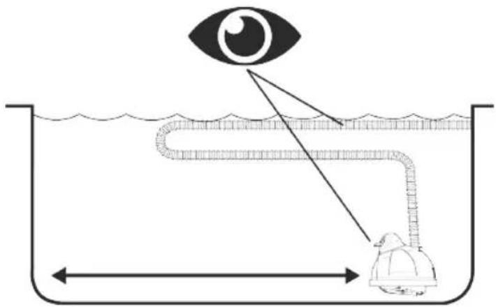
Submerge the cleaner into the water to remove all air.
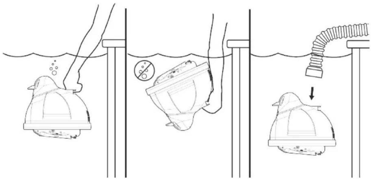
Step 7

natural_image
Diagram showing a submerged object with a curved arrow pointing to it, above and below a wavy line (no text or symbols)
OFF

natural_image
Prohibition sign showing a helmet crossed out by a diagonal line, no text or symbols present
natural_image
Line drawing of a mechanical component with a spiral top and checkmark below (no text or symbols)Step 8

ON
Turn pump on and observe cleaner.

IMPORTANT TIPS

Periodically check the water flow/vacuum to be sure that your cleaner is operating as efficiently as possible.
Remember, too much vacuum is just as bad as too little.

Periodically check to make sure that the cleaner hose is securely attached to its suction source (i.e. skimmer, wall connector, etc.).

Disconnect the cleaner hose from the skimmer/regulator valve prior to "backwashing", in order not to restrict water flow.

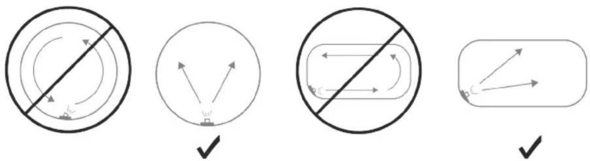
DO NOT COIL HOSE
When storing your cleaner, the hose sections must be stored straight. A coiled hose will create a memory in the hose that will impede the cleaner's ability to move properly.

Coiled hoses are not covered under the Hayward warranty.
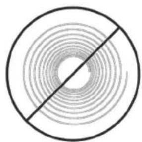
natural_image
Concentric circles divided by a diagonal line, no text or symbols present
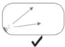
Adjust the water return toward the center of the pool so water circulation does not interfere with the cleaner's pool coverage capability.

Use only original Hayward spare parts and hoses to ensure proper operation.

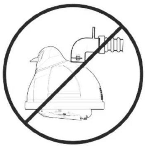
When the cleaner is out of the pool, always disconnect the leader hose from the cleaner.

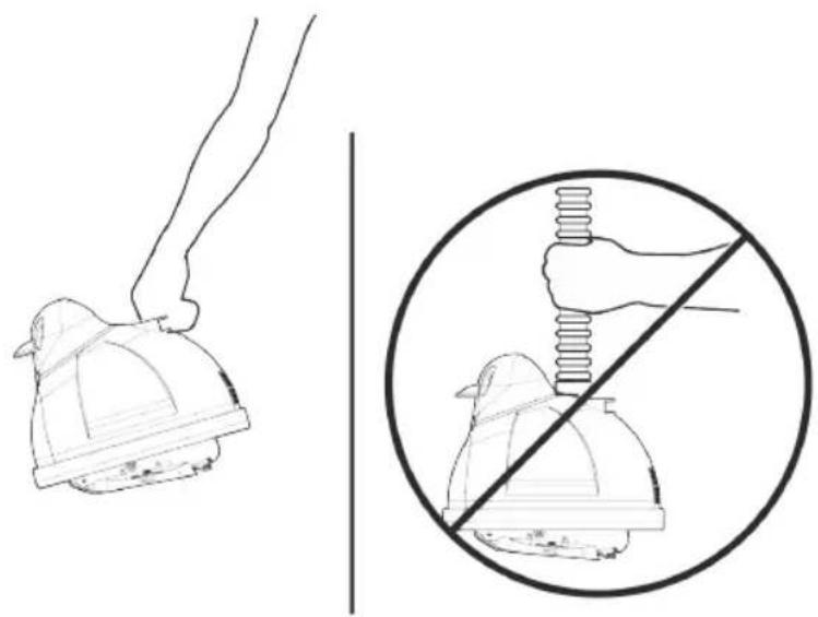
natural_image
Illustration showing a hand holding a helmet and a circular diagram of a hand using a spring, with no text or symbols present.


natural_image
Simple line drawing of a container with a pipe and a circular symbol indicating no prohibition (no text or labels)MAINTENANCE TIPS
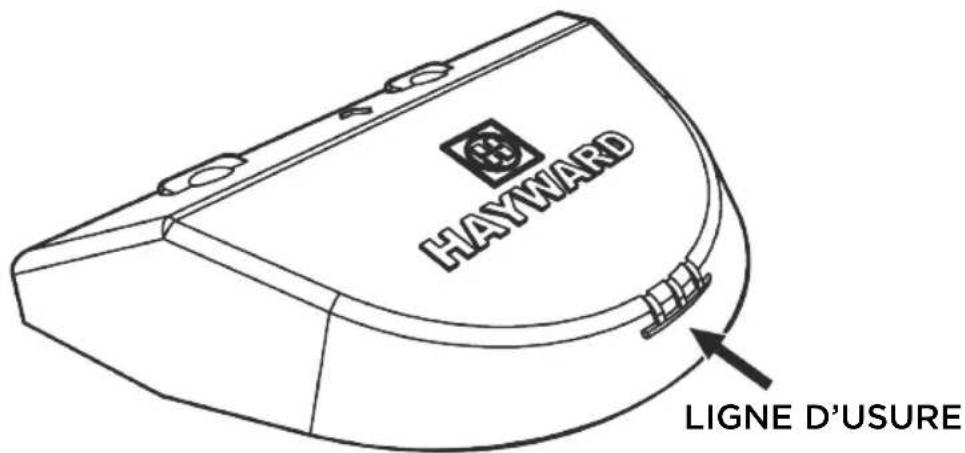
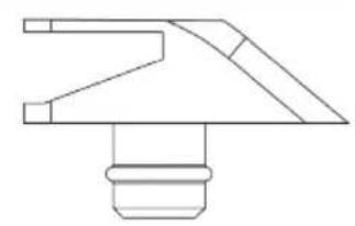
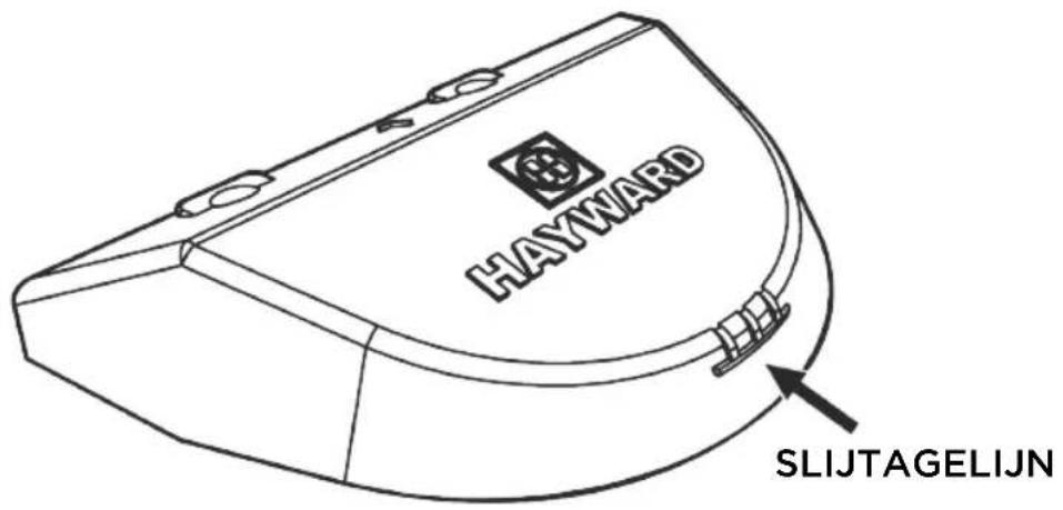
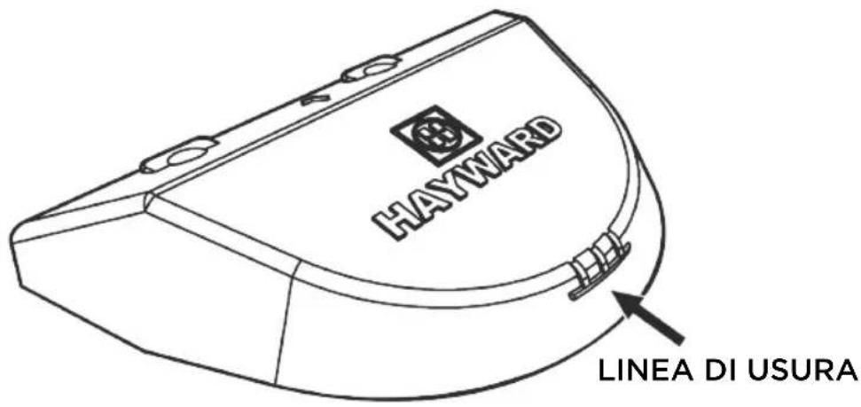
Check the condition of the "shoes, wings, and flaps" periodically.
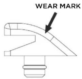
GOOD SHOE
natural_image
Pure technical line drawing of a mechanical component (no text or symbols)WORN SHOE

Hayward is not responsible for damage caused by misuse of the cleaner or damage caused by worn or broken parts.
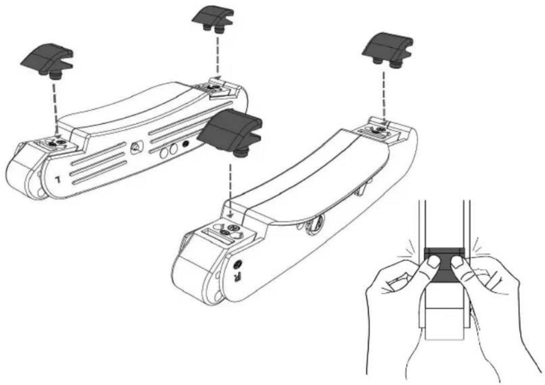
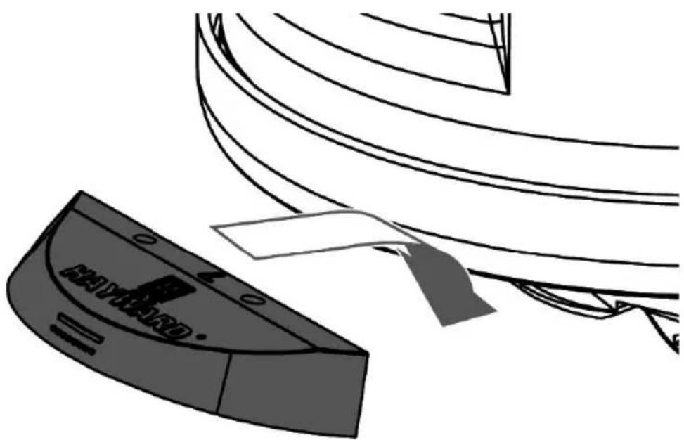
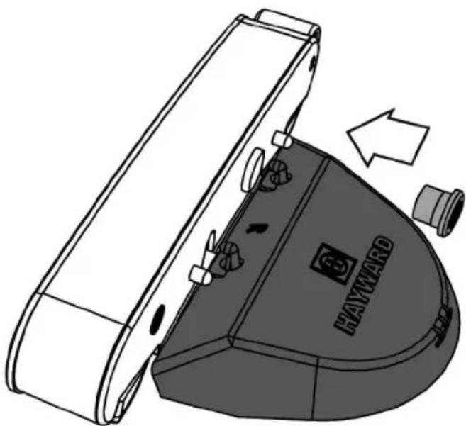
Shoe Replacement:
Step 1
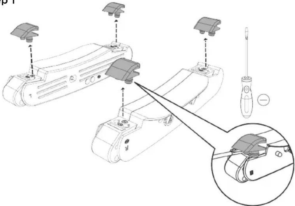
Step 2

natural_image
Line drawing of a handheld device with multiple camera modules and a close-up of its handle (no text or symbols)MAINTENANCE TIPS
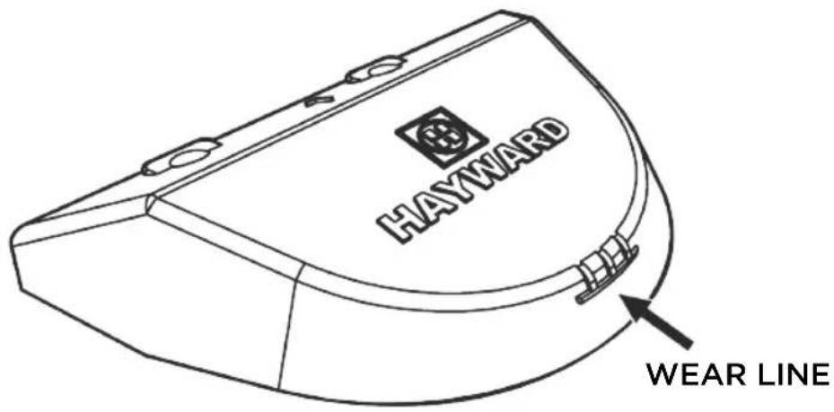
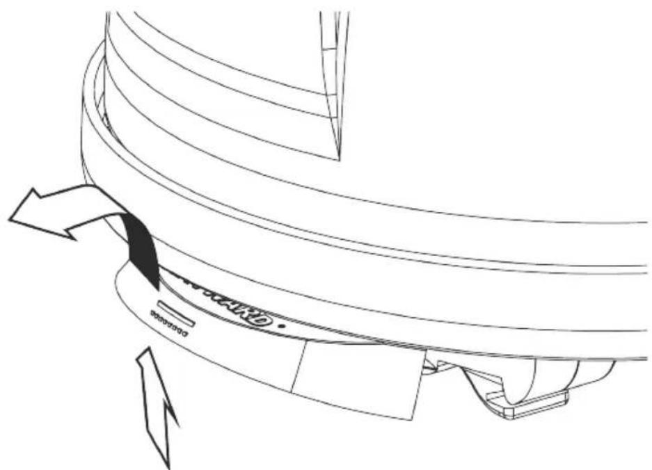
Wing Replacement:
Step 1

Step 2
natural_image
Technical line drawing of a curved mechanical component with directional arrows indicating motion or force (no text or symbols)Step 3

natural_image
Illustration of a curved mechanical component with a triangular base and a triangular load, no text or symbols present.Step 4

natural_image
Technical line drawing of a Hayward industrial machine component with no visible text or symbolsTROUBLESHOOTING
| PROBLEM CAUSES SOLUTION | ||
| Slow/no forward movement | Lack of/improper water flow through cleaner | Check water flow with flow gauge and adjust as per Step 5. |
| Blockage of the cleaner throat | Clear blockage | |
| Worn shoes | Replace shoes | |
| Worn wings | Replace wings | |
| Improper cleaner model for application | See your pool dealer or servicer. | |
| Cleaner head “floats” | Air trapped in the head | Remove all air from cleaner head. Stop all air from entering the pool through the return lines. If cleaner head and hose are covered with fine bubbles, give the hose a good tug. This will release the air bubbles and allow the cleaner head to settle to the bottom of the pool until the hose is covered with bubbles again. |
| The cleaner head is actually being pulled or lifted off the bottom of the pool by the cleaner hose, or return line flow -either at the surface or at the bottom of the pool-or both. | Readjust return outlets to prevent water flow interfering with cleaner head and/or hose. | |
| Cleaner sticks at ladder, corners, etc. | Improper water flow | Check water flow with flow gauge and adjust as per Step 5. |
| Worn shoes Replace shoes | ||
| Worn wings Replace wings | ||
| Hose too short | Install additional hose sections per installation instructions. | |
| Steering failure 1. Check and clean rear screen, if necessary2. Check to see that cone gear is free of debris and rotates smoothly in both directions3. Check steering program and troubleshoot -then:a. clean, repair or replace gearboxb. check pod/A-frame connection and REPLACE IF NECESSARY. DO NOT ATTEMPT TO RETIGHTEN LOOSE PODSc. check medium turbine and spindle gear assemblies | ||
WARRANTY
HAYWARD LIMITED WARRANTY
All HAYWARD products are covered for manufacturing defects or material defects for a warranty period of 2 years as of date of purchases. Any warranty claim should be accompanied by evidence of purchase, indicating date of purchase. We would therefore advise you to keep your invoice.
The HAYWARD warranty is limited to repair or replacement, as chosen by HAYWARD, of the faulty products, provided that they have been subjected to normal use, in compliance with the guidelines given in their user guides, provided that the products have not been altered in any way, and provided that they have been used exclusively with HAYWARD parts and components. The warranty does not cover damage due to frost and to chemicals. Any other costs (transport, labour, etc.) are excluded from the warranty. HAYWARD may not be held liable for any direct or indirect damage resulting from incorrect installation, incorrect connection, or incorrect operation of a product.
In order to claim on a warranty and in order to request repair or replacement of an article, please ask your dealer.
No equipment returned to our factory will be accepted without our prior written approval.
Wearing parts are not covered by the warranty.
HAYWARD
natural_image
Simple line icon of an open book (no text or symbols)natural_image
Three technical line drawings of a mechanical component, showing different views (top, front, side) with no visible text or symbols.Limpiafondos
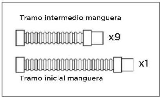
Tramo intermedio manguera / Tramo inicial manguera
natural_image
Line drawing of a person using a long tool to catch fish, with no text or symbols presentRESIDUOS
natural_image
Three identical black test tubes with liquid, no text or symbols present
pH: 7,2 a 7,6
Cloro: 1,0 a 3,0 ppm
natural_image
Diagram showing two hands holding a small object with bidirectional arrows indicating movement or force (no text or symbols)Etapa 1
flowchart
graph TD
    A["Bottom Component"] --> B["Stage 1st"]
    B --> C["Stage 2nd"]
    style A fill:#f9f,stroke:#333
    style C fill:#bbf,stroke:#333
Etapa 2
Etapa 7

natural_image
Diagram showing a submerged object with a curved arrow pointing to it, above and below a wavy line (no text or symbols)
OFF

natural_image
Prohibition sign showing a helmet crossed out by a diagonal line, no text or symbols present
natural_image
Line drawing of a mechanical component with a threaded top and a checkmark below (no text or symbols)Etapa 8

ON
natural_image
Circular diagram with concentric rings and a diagonal line crossing through the center (no text or symbols)
natural_image
Simple circular diagram with concentric rings and a diagonal line crossing through, no text or symbols present.
natural_image
Simple diagram with a circle and two arrows pointing outward, one with a checkmark below (no text or symbols)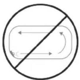
flowchart
graph TD
    A["Start"] --> B{Split}
    B --> C["Loop Back"]
    C --> D["End"]

natural_image
Simple diagram with arrows pointing to a rounded rectangle and a checkmark below (no text or symbols)
natural_image
Illustration showing a hand holding a helmet and a circular diagram of a hand using a spring, with no text or symbols present.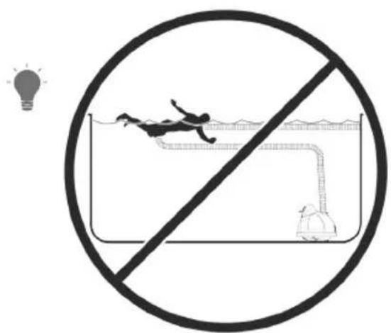
CONSEJOS DE MANTENIMIENTO
natural_image
Pure mechanical component diagram without any text, numbers, or symbolsSUELA EN BUEN ESTADO

natural_image
Pure technical line drawing of a mechanical component without any text, numbers, or symbolsSUELA DESGASTADA
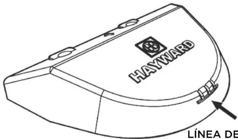
LÍNEA DE DESGASTE

Etapa 2
natural_image
Line drawing of a handheld device with multiple camera modules and a close-up of its handle (no text or symbols)CONSEJOS DE MANTENIMIENTO
natural_image
Technical line drawing of a curved mechanical component with directional arrows indicating motion or force (no text or symbols)Etapa 3

natural_image
Illustration of a curved mechanical component with a triangular base and a triangular load, no text or symbols present.Etapa 4

natural_image
Technical line drawing of a Hayward industrial machine component with no visible text or symbolsnatural_image
Line drawing of a mechanical component with a lever and circular features (no text or symbols)
natural_image
Line drawing of a helmet with no text or symbols
natural_image
Line drawing of a mechanical component or housing with no visible text or symbols
natural_image
Simple line icon of an open book with an information symbol inside (no text or numbers)
natural_image
Simple line drawing of an open book with no text or symbols visiblenatural_image
Three technical line drawings of a mechanical component, showing different views (top, front, side) with no visible text or symbols.Robô de limpeza
natural_image
Line drawing of a person spraying water with a long tool, no text or symbols presentDETRITOS
natural_image
Three identical test tubes with liquid, no text or symbols present
pH: 7,2 a 7,6
Cloro: 1,0 a 3,0 ppm
Alcalinidade total: 80 a 120 ppm
EQUILÍBRIO QUÍMICO DA ÁGUA
natural_image
Diagram showing two hands adjusting a belt buckle with directional arrows indicating movement (no text or symbols)Etapa 1
flowchart
graph TD
    A["Section 1st"] --> B["Section 2nd"]
    B --> C["Bottom Section"]
    style A fill:#f9f,stroke:#333
    style B fill:#ccf,stroke:#333
    style C fill:#cfc,stroke:#333
Etapa 2
natural_image
Diagram showing a submerged object with a curved arrow pointing to it, above and below a wavy line (no text or symbols)
OFF

natural_image
Prohibition sign showing a helmet crossed out by a diagonal line, no text or symbols present
natural_image
Line drawing of a mechanical component with a spiral top and checkmark below (no text or symbols)Etapa 8

ON
Pôr a bomba a funcionar e observar o robô..
SUGESTÕES IMPORTANTES

natural_image
Circular diagram with concentric rings and a diagonal line crossing through the center (no text or symbols)
natural_image
Simple circular diagram with concentric rings and a diagonal line crossing through, no text or symbols present.
natural_image
Simple diagram with a circle and two arrows pointing outward, one with a black checkmark at the bottom (no text or symbols)
flowchart
graph TD
    A["Start"] --> B{Split}
    B -->|Yes| C["Loop Back"]
    B -->|No| D["End"]

natural_image
Simple diagram with arrows pointing outward from a central point, enclosed in a rounded rectangle with a checkmark below (no text or symbols)
natural_image
Illustration showing a hand holding a helmet and a circular diagram of a hand using a spring, with no text or symbols present.


natural_image
Simple line drawing of a container with a pipe and a circular symbol indicating no prohibition (no text or labels)natural_image
Pure mechanical component diagram without any text, numbers, or symbolsSAPATA EM BOM ESTADO
natural_image
Pure technical line drawing of a mechanical component without any text, numbers, or symbolsSAPATA GASTA
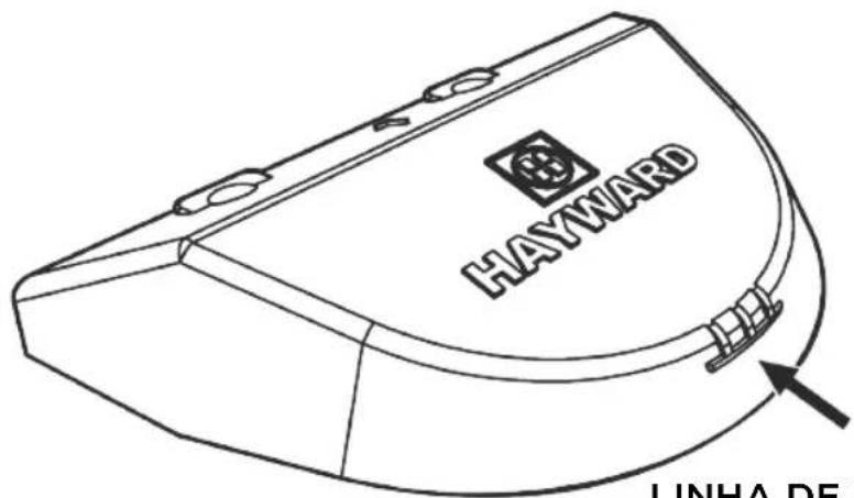
LINHA DE DESGASTE

Etapa 2

natural_image
Line drawing of a handheld device with multiple camera modules and a close-up of its handle (no text or symbols)natural_image
Technical line drawing of a curved mechanical component with directional arrows indicating motion or force (no text or symbols)Etapa 3

natural_image
Illustration of a curved mechanical component with a triangular base and a triangular load, no text or symbols present.Etapa 4

natural_image
Technical line drawing of a Hayward industrial machine component with no visible text or symbolsnatural_image
Line drawing of a bread roll with a spoon (no text or symbols)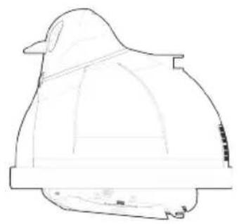
natural_image
Line drawing of a helmet with a wide brim and flat blade (no text or symbols)
natural_image
Line drawing of a mechanical component or housing with no visible text or symbols
natural_image
Simple line icon of an open book with an information symbol inside (no text or numbers)
natural_image
Simple line drawing of an open book with no text or symbols visiblePOOLSAUGER MIT TURBINE
Benutzerhandbuch
natural_image
Three technical line drawings of a mechanical component, showing different views (top, front, side) with no visible text or symbols.Reinigungsroboter

natural_image
Line drawing of a person spraying water with a tool, no text or symbols presentVERUNREINIGUNGEN
natural_image
Three identical black test tubes with liquid, no text or symbols present
pH: 7,2 bis 7,6
natural_image
Diagram showing two hands holding a small object with bidirectional arrows indicating movement or force (no text or symbols)Schritt 1
Schritt 7

OFF


natural_image
Prohibition sign showing a helmet crossed out by a diagonal line, no text or symbols present
natural_image
Line drawing of a mechanical component with a threaded top and base, no text or symbols presentSchritt 8

ON
WICHTIGE HINWEISE

natural_image
Circular diagram with concentric rings and a diagonal line crossing through the center (no text or symbols)
natural_image
Illustration showing a hand holding a helmet and a circular diagram of a hand using a spring, with no text or symbols present.

natural_image
Pure mechanical component diagram without any text, numbers, or symbolsnatural_image
Pure technical line drawing of a mechanical component without any text, numbers, or symbolsSchritt 2

natural_image
Line drawing of a handheld device with multiple camera modules and a close-up of its handle (no text or symbols)natural_image
Technical line drawing of a curved mechanical component with directional arrows indicating movement or force (no text or symbols)Schritt 3

natural_image
Illustration of a curved mechanical component with a triangular base and a triangular load, no text or symbols present.Schritt 4

natural_image
Technical line drawing of a Hayward industrial machine component with no visible text or symbolsnatural_image
Line drawing of a small container with a straw and lid, no text or symbols present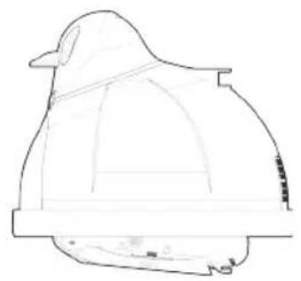
natural_image
Line drawing of a helmet with no text or symbols
natural_image
Line drawing of a mechanical component or housing with no visible text or symbols
natural_image
Simple line icon of an open book with an information symbol inside (no text or numbers)
natural_image
Simple line icon of an open book (no text or symbols)ZUIGROBOT MET TURBINE
Gebruikshandleiding
natural_image
Three technical line drawings of a mechanical component, showing different views (top, front, side) with no visible text or symbols.Zwembadreiniger
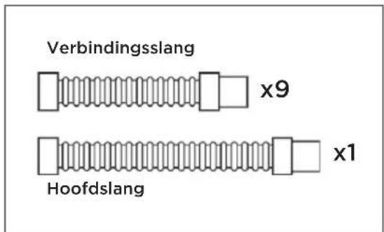
Verbindingsslang/Hoofdslang
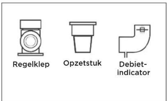
Meegeleverde accessoires
HET ZWEMBAD VOORBEREIDEN
natural_image
Line drawing of a person spraying water with a long tool, no text or symbols presentVUIL
natural_image
Three identical test tubes with liquid, no text or symbols present
pH: 7,2 tot 7,6
Chloor: 1,0 tot 3,0 ppm
natural_image
Diagram showing two hands holding a small object with bidirectional arrows indicating movement or force (no text or symbols)Stap 1
Stap 7

natural_image
Diagram showing a submerged object with a curved arrow pointing to it, above and below a wavy line (no text or symbols)
OFF
natural_image
Prohibition sign showing a helmet crossed out by a diagonal line, no text or symbols present
natural_image
Line drawing of a mechanical component with a threaded top and base, no text or symbols presentStap 8

ON
BELANGRIJKE TIPS

natural_image
Circular diagram with concentric rings and a diagonal line crossing through the center (no text or symbols)
flowchart
graph TD
    A["Circle with diagonal line crossing"] --> B["Circle with arrows pointing inward"]
    B --> C["Circle with horizontal line crossing"]
    C --> D["Rectangle with arrows pointing inward"]
    style A fill:#fff,stroke:#000
    style B fill:#fff,stroke:#000
    style C fill:#fff,stroke:#000
    style D fill:#fff,stroke:#000

natural_image
Illustration showing a hand holding a helmet and a circular diagram of a hand using a spring, with no text or symbols present.


natural_image
Simple line drawing of a container with a pipe and a circular symbol indicating no prohibition (no text or labels)ONDERHOUDSTIPS
natural_image
Pure mechanical component diagram without any text, numbers, or symbols
natural_image
Pure technical line drawing of a mechanical component without any text, numbers, or symbolsVERSLETEN GLIJBLOKJE
GLIJBLOKJE
IN GOEDE CONDITIE

Stap 2

natural_image
Line drawing of a device with labeled parts and a close-up of hands holding a connector (no text or symbols present)ONDERHOUDSTIPS
Vleugels vervangen:
Stap 1
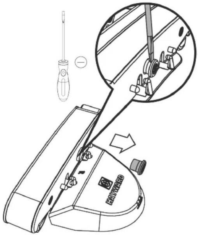
Stap 2
natural_image
Technical line drawing of a curved mechanical component with directional arrows indicating movement or force (no text or symbols)Stap 3

natural_image
Illustration of a curved mechanical component with a triangular base and a triangular load, no text or symbols present.Stap 4

natural_image
Technical line drawing of a Hayward industrial machine component with no visible text or symbolsPROBLEMEN IDENTIFICEREN
EN OPLOSSEN
natural_image
Simple line icon of an open book with an information symbol inside (no text or numbers)
natural_image
Simple line icon of an open book (no text or symbols)ROBOT AD ASPIRAZIONE A TURBINA
Manuale per l'uso
natural_image
Three technical line drawings of a mechanical component, showing different views (top, front, side) with no visible text or symbols.Pulitore
natural_image
Line drawing of a person spraying water with a long tool, no text or symbols presentDETRITI
natural_image
Three identical black test tubes with liquid, no text or symbols present
pH: da 7,2 a 7,6
Cloro: da 1,0 a 3,0 ppm
natural_image
Diagram showing two hands holding a small object with bidirectional arrows indicating movement or force (no text or symbols)Fase 1
Fase 7

natural_image
Diagram showing a submerged object with a curved arrow pointing to it, above and below a wavy line (no text or symbols)
OFF

natural_image
Prohibition sign showing a helmet crossed out by a diagonal line, no text or symbols present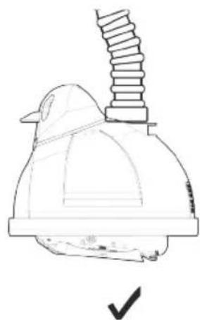
natural_image
Line drawing of a mechanical component with a threaded top and base, no text or symbols presentFase 8

ON
CONSIGLI IMPORTANTI

natural_image
Circular diagram with concentric rings and a diagonal line crossing through the center (no text or symbols)
natural_image
Circular diagram with concentric rings and a diagonal line crossing through, no text or symbols present.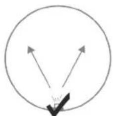
natural_image
Simple diagram with a circle and two arrows pointing outward, one with a checkmark at the bottom (no text or symbols)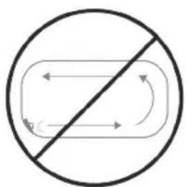
flowchart
graph TD
    A["Start"] --> B{Split}
    B -->|Path 1| C["Loop Back"]
    B -->|Path 2| D["Loop Back"]
    C --> E["End"]
    D --> E
    E --> F["End"]
natural_image
Simple diagram with arrows pointing to a rounded rectangle and a checkmark below (no text or symbols)
natural_image
Illustration showing a hand holding a helmet and a circular diagram of a hand using a spring, with no text or symbols present.


natural_image
Simple line drawing of a container with a pipe and a circular symbol indicating no prohibition (no text or labels)natural_image
Pure mechanical component diagram without any text, numbers, or symbolsnatural_image
Pure technical line drawing of a mechanical component (no text or symbols)PIEDINO CONSUMATO

Fase 2

natural_image
Line drawing of a handheld device with multiple camera modules and a close-up of its handle (no text or symbols)natural_image
Technical line drawing of a curved mechanical component with directional arrows indicating motion or force (no text or symbols)Fase 3
natural_image
Illustration of a curved mechanical component with a triangular base and a triangular load, no text or symbols present.Fase 4
natural_image
Technical line drawing of a Hayward industrial machine component with no visible text or symbols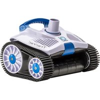


- HAYWARD®
- ROBOTS HORS SOL
- Robot à aspiration
- DÉBRIS
- Étape 1
- Étape 2
- Étape 8
- CONSEILS IMPORTANTS
- CONSEILS DE MAINTENANCE
- Suction Pool Cleaner
- Owner's Manual
- TURBINE SUCTION CLEANER
- FOR YOUR RECORDS
- SAFETY WARNINGS
- KEY
- PREPARING THE POOL
- Please complete the following steps to prepare your pool for installation:
- DEBRIS
- WATER LEVEL
- WATER CHEMISTRY
- FILTER
- Sizing Suction Hose
- Step 1
- Step 2
- Step 3
- INSTALLATION
- Step 4
- Connecting to skimmer:
- Step 5
- Reading Too High?
- To install the Hayward regulator valve:
- Reading Too Low?
- Step 6
- Step 8
- IMPORTANT TIPS
- DO NOT COIL HOSE
- MAINTENANCE TIPS
- Shoe Replacement:
- Wing Replacement:
- TROUBLESHOOTING
- WARRANTY
- HAYWARD LIMITED WARRANTY
- HAYWARD
- RESIDUOS
- Etapa 1
- Etapa 2
- Etapa 8
- CONSEJOS DE MANTENIMIENTO
- DETRITOS
- EQUILÍBRIO QUÍMICO DA ÁGUA
- SUGESTÕES IMPORTANTES
- POOLSAUGER MIT TURBINE
- Benutzerhandbuch
- VERUNREINIGUNGEN
- Schritt 1
- Schritt 8
- WICHTIGE HINWEISE
- ZUIGROBOT MET TURBINE
- Gebruikshandleiding
- HET ZWEMBAD VOORBEREIDEN
- VUIL
- Stap 1
- Stap 8
- BELANGRIJKE TIPS
- ONDERHOUDSTIPS
- Vleugels vervangen:
- PROBLEMEN IDENTIFICEREN
- EN OPLOSSEN
- ROBOT AD ASPIRAZIONE A TURBINA
- Manuale per l'uso
- DETRITI
- Fase 1
- Fase 8
- CONSIGLI IMPORTANTI
Brand : HAYWARD
Model : Whaly
Category : Vacuum Cleaner