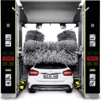
CW 5 Klean!Star Q - Automatic car wash Kärcher - Free user manual and instructions
Find the device manual for free CW 5 Klean!Star Q Kärcher in PDF.
| Product type | Automatic gantry car wash |
| Model | CW 5 Klean!Star Q |
| Brand | Kärcher |
| Washing height | 2100 to 2900 mm depending on configuration |
| Total height | 2930 to 3730 mm |
| Total width (with side brushes) | 4040 mm |
| Depth | 2170 mm |
| Brush diameter (side and roof) | 975 mm |
| Side brush rotation speed | 107 rpm |
| Roof brush rotation speed | 127 rpm |
| Gantry speed | 0 to 24 m/min |
| Power supply | 400 V / 50 Hz / 10-16 kW |
| Water connection | 1 inch, pressure 0.4-0.6 MPa, max 50 °C |
| Compressed air connection | 1/2 inch, pressure 0.6-0.8 MPa |
| Noise level (washing + drying) | 87 dB(A) |
| Water consumption per wash (vehicle 4.5 m) | Approximately 50 liters (without antifreeze) |
| Main functions | High-pressure washing, brushing, foam, wax, drying, degreasing, rim cleaning |
| Safety | Emergency stop, safety switches, anti-tilt protection, safety valve |
| Maintenance | Daily cleaning of nozzles, filters, barriers; weekly, monthly, semi-annual and annual maintenance |
| Spare parts | Use only genuine Kärcher parts |
Frequently Asked Questions - CW 5 Klean!Star Q Kärcher
User questions about CW 5 Klean!Star Q Kärcher
0 question about this device. Answer the ones you know or ask your own.
Ask a new question about this device
Download the instructions for your Automatic car wash in PDF format for free! Find your manual CW 5 Klean!Star Q - Kärcher and take your electronic device back in hand. On this page are published all the documents necessary for the use of your device. CW 5 Klean!Star Q by Kärcher.
USER MANUAL CW 5 Klean!Star Q Kärcher
natural_image
White car under a robotic lift with multiple car wheelbars, no visible text or symbols on the vehicle or background.Deutsch 2
English 24
Français 46
Italiano 70
Nederlands 94
Español 118
Português 142
Dansk 166
Norsk 188
Svenska 210
Suomi 232
Ελληνικά 254
Русский 279
Magyar 304
Inhalt
text_image
Technical diagram of an industrial control room with numbered components and wiring, including a stop unit and internal electronics display.text_image
Diagram of a car cleaning or dust removal system with numbered components and labeled parts in Chinesetext_image
C3 C2 C1 H4 B2 B1 H3 L K G H2 A2 A1 A3text_image
Diagram of an electrical control cabinet with labeled components including switches, a red socket, and warning labelstext_image
Electrical control panel with numbered components and labeled switches, wires, and meters①Dosierpumpe
②Dosierpumpe Shampoo
③Dosierpumpe Schaum
④Dosierpumpe Wachs 1
⑤Dosierpumpe Vorreinigung (Insekten)
⑥Dosierpumpe Wachs 2
⑦Dosierpumpe Felgenreiniger (Felgenschaum)
⑧Dosierpumpe Polieren
text_image
① ↑ ② STOP ↓ ③①Vorwärts fahren
natural_image
3D rendering of a white plastic container with a black cap and threaded screw, labeled with parts 1 and 2 (no text or symbols on the main subject)text_image
Technical diagram of an industrial control room with numbered components and labeled parts, including a stop unit and electrical equipment.text_image
Diagram of a car cleaning or maintenance system with numbered components and close-ups of mechanical components, including brooms, hoses, and sensors.natural_image
Close-up of a metal pipe joint with two circular components, no visible text or symbols
natural_image
Close-up of concrete structural beams and a small circular component with two rings, no visible text or symbols
natural_image
Close-up of a metallic industrial control box with a circular eye and three screws, mounted on a wall (no visible text or symbols)
natural_image
Three industrial pipe fittings with brass and metallic components, no visible text or symbols④ ③
text_image
Technical diagram of a pressure regulator with labeled parts including valve, fittings, and adjustment knobstext_image
Technical diagram showing exploded and assembled views of a mechanical device with numbered componentstext_image
Technical diagram of a pump system with labeled components and an inset view showing internal components.①Kreiselpumpe
H. Jenner
Chairman of the Board of Management
S. Reiser
Manager Regulatory Affairs & Certification
71364 Winnenden (Germany)
Tel.: +49 7195 14-0
Fax: +49 7195 14-2212
Winnenden, 2022/11/01
Contents
General notes 24
Environmental protection 24
Safety instructions 24
Intended use 26
Water connection 26
Accessories and spare parts.... 27
System description.... 27
Control elements.... 30
Display description.... 32
Start-up 34
Operation 34
Shutting down 37
Care and service.... 37
Troubleshooting guide 42
Warranty 45
Technical data.... 45
Declaration of Conformity 46
General notes
Read these original operating instructions and the safety instructions chapter before using the device for
the first time. Act in accordance with them.
Keep them safe for future reference or for future owners.
Environmental protection
The packing materials can be recycled. Please dispose of packaging in accordance with the environmental regulations.
Electrical and electronic devices contain valuable, recyclable materials and often components such as batteries, rechargeable batteries or oil, which - if handled or disposed of incorrectly - can pose a potential danger to human health and the environment. However, these components are required for the correct operation of the device. Devices marked by this symbol are not allowed to be disposed of together with the household rubbish.
Notes on the content materials (REACH)
Current information on content materials can be found at: www.kaercher.de/REACH
Safety instructions
Dangers can be presented to the operator and other persons if the device is incorrectly operated or misused:
• High water pressure
• High electrical voltage
- Compressed air
- Detergent
To avoid danger to persons, animals and property, read the following documents before operating the system:
- The operating instructions, including all safety instructions
• The respectively applicable national regulations
- The safety instructions provided with the detergent used
Ensure the following:
• That you have understood all notes and instructions
- That all users of the system are notified of the instructions and have understood them
All persons working on the erection, commissioning and operation of the system must:
- Be appropriately qualified
- Know and adhere to the operating instructions
- Know and adhere to the applicable regulations
In self-service operation, ensure that clearly visible notices are present informing all users with regard to:
• Potential dangers
- Safety devices
- Operating the system
The owner/operator of the washing bay is to create work instructions based on these operating instructions, the local conditions and the personnel conditions. The operating instructions are to be made available by providing copies or hanging signs with corresponding content in the workplace.
Hazard levels
△DANGER
- Indication of an imminent threat of danger that will lead to severe injuries or even death.
△WARNING
- Indication of a potentially dangerous situation that may lead to severe injuries or even death.
△CAUTION
- Indication of a potentially dangerous situation that may lead to minor injuries.
ATTENTION
- Indication of a potentially dangerous situation that may lead to damage to property.
Regulations and guidelines
In the Federal Republic of Germany, the following regulations and guidelines apply to the operation of this system (available from Carl Heymanns Verlag KG, Luxemburger Straße 449, 50939 Cologne):
- Accident prevention regulations "General regulations" BGV A1
• Vehicle washing plant safety EN 17281
• German work safety directive (BetrSichV)
Vehicle washing plants
Only persons familiar with the work, the operating instructions and the dangers associated with the system are permitted to operate, monitor, care for and inspect car wash systems.
Waste water containing mineral oil
ATTENTION
Environmental pollution through vehicles
Escaping oils.
Protect the ground and dispose of old oil in an environmentally-friendly manner.
Do not allow gear oil and waste water containing mineral oil to enter the soil or waterways.
Treat the waste water before channelling it into the sewage system.
Observe the locally applicable statutory regulations and waste water treatment regulations.
Self-service
In self-service systems, a person must always be available during operating periods, who is familiar with the washing bay and can take or initiate the measures necessary for preventing potential dangers in the case of a system malfunction.
Clearly visible instructions on the operation and intended use of the washing system must be provided at the washing bay for the users of the washing system.
Maintenance and servicing
The washing bay must always be shut down when performing maintenance and servicing work.
⚠ WARNING
Risk of injury from machine movements
Switch the system off before performing maintenance and servicing work.
Secure the main switch with a padlock to prevent it from being switched on again.
Operation with detergent
⚠ WARNING
Danger from substances in detergents that present a hazard to health
Observe the safety data sheets for the detergents used.
Adhere to the prescribed safety measures.
Wear the prescribed protective clothing such as safety goggles and protective gloves.
ATTENTION
Increased risk of corrosion through the use of unsuitable cleaning agents
Do not use the following cleaning agents in the system:
Detergents intended for cleaning the washing hall.
Detergents intended for externally cleaning the washing bay.
Acidic cleaning agents.
Cleaning agents applied to the vehicle using a separate device (e.g. wheel cleaner).
Water treatment agents.
Entering the portal washing station
△DANGER
Danger through entering the portal washing station
Prohibit unauthorised persons from entering the portal washing station.
Erect suitable permanent signage indicating prohibited entry.
Risk of slipping
ATTENTION
Risk of slipping on wet surfaces
Wear suitable shoes when entering the system and exercise care when walking.
Erect suitable permanent signage informing customers of the danger of slipping.
Operating the system
△WARNING
Danger through incorrect operation
Persons operating the system must:
Be instructed in the correct handling of the system,
Have provided verification of their ability to operate the system, Be explicitly nominated to operate the system.
The operating instructions must be accessible to all operators.
The system may not be operated by persons under 18 years of age. This does not include supervised trainees of 16 years of age or more.
⚠ WARNING
Risk of tripping over objects or supply lines lying on the ground
Remove all objects lying in the washing station before starting the system.
Danger of frost
⚠ WARNING
Risk of injury or damage due to the formation of ice in the system
Drain all water from the system if there is a danger of frost.
Keep all footpaths slip-free (e.g. floor heating, gravel).
Workstation
The system is started via the control panel or via a wash card/code reader.
- The occupants must leave the vehicle before washing.
- Entering the system before washing has finished is prohibited.
Danger sources
General dangers
△DANGER
Risk of injury from escaping compressed air, high-pressure water at nozzle outlets and propelled dirt particles or similar in the vicinity of the rotating brushes!
Dirt particles or loose objects can injure persons or animals when propelled off the vehicle.
Compressed air or high-pressure water can remain pressurised even when the system is switched off.
Keep the hall floor free of loose lying objects.
Exercise care when operating the compressed air system and the high-pressure system.
Wear suitable safety goggles when performing maintenance work.
Risk of explosion
DANGER
Risk of explosion
Do not operate the system in the vicinity of potentially explosive spaces. Systems specifically designed for this, and labelled accordingly, are exempt from this stipulation
Do not use explosive or poisonous substances as cleaning
agents, e.g.:
- Petrol
• Heating oil or diesel fuel
- Solvents
• Liquids containing solvents
- Acids
- Acetone
Note
Contact the manufacturer if you are unsure.
Hearing damage
The noises emitted by the system are not hazardous for the washing customers due to the short exposure time.
Note
The sound level at the entry side during dry operation is 91 dB(A).
△WARNING
Risk of hearing damage to the operating personnel during drying mode
Wear hearing protection during drying mode.
Hearing damage due to high volume in the machine room
Wear suitable hearing protection when staying in the machine room.
Electrical hazards
△DANGER
Danger of electric shock
Never touch electrical components and cables with wet hands.
Ensure that the electrical connection cables or extension cable are not damaged by being driven over, crushed, yanked or similar.
Protect the cables from heat, oil and sharp edges.
Never point a water jet at electrical devices or systems.
Protect all live components in the work area from water jets.
Connect the system only to correctly earthed power sources.
Allow only qualified electricians to work on electrical components of the system.
Substances harmful to health
△DANGER
Danger due to harmful substances
Be sure to observe the information and notes provided with the detergent.
Never drink water expelled from the system! The water is not of drinking water quality due to the added cleaning agents.
Observe the anti-bacterial regulations of the treatment system manufacturer when using processed water for operating the system.
Ensure that materials not normally present during exterior cleaning of vehicles (e.g. heavy metals, pesticide, radioactive materials, faeces or infectious materials) do not enter the washing bay.
Danger due to power failure
Design measures are to be taken to ensure that uncontrolled re-starting of the system after a power failure is impossible.
Environmental hazard due to waste water
Observe the local waste water disposal regulations.
Servicing and monitoring
The corresponding instructions must be followed to ensure safe operation of the system and avoid dangers during maintenance, monitoring and inspection.
Maintenance and servicing
Maintenance work must be performed as specified by the manufacturer by a technically qualified person at the specified regular intervals. Observe the applicable regulations and safety requirement. Allow only qualified electricians to work on the electrical system.
⚠ WARNING
Risk of injury from machine movements
Switch the system off before performing maintenance and servicing work.
Secure the main switch with a padlock to prevent it from being switched on again.
⚠ WARNING
Risk of injury from pressurised compressed air reservoirs and lines after the system has been switched off
Depressurise the system before performing any work on the system.
Check the pressure gauge at the maintenance unit to ensure that the system is depressurised.
⚠ WARNING
Risk of injury from the high-pressure system after the system has been switched off
Depressurise the high-pressure system before performing any work on the system.
Monitoring
This washing bay must be inspected by a technically qualified person to ensure a safe condition before initial commissioning and then at half-yearly intervals at the very least.
This inspection includes especially:
- A visual inspection for all externally visible signs of wear and tear or damage
- Function test
- The completeness and effectiveness of all safety devices at self-service stations must be checked daily before the start or operations, or as required on monitored systems but always at least once a month.
Use only original parts
Use only original manufacturer spare parts or parts recommended by the original manufacturer, otherwise all warranty claims will be invalidated.
Adhere to all safety instructions and application instructions provided with these parts.
This applies to:
- Spare parts and wearing parts
- Accessories
- Operating materials
- Detergent
Safety devices
The high-pressure pumps for the supply of the underbody washing unit and the high-pressure wash have the following safety devices.
Safety valve
The safety valve opens when the permissible operating pressure is exceeded and the water flows into the open.
Intended use
This washing bay is exclusively intended for external cleaning of passenger vehicles with standard equipment and closed delivery vehicles.
Adherence to the intended use also includes:
- Adherence to all information provided in these operating instructions.
- Adherence to the inspection and maintenance instructions.
ATTENTION
Risk of damage to vehicles when using the CareTouch brushes
Equip the system with a high pressure attachment kit or pre-wash the vehicles when using the CareTouch brushes.
Be aware of the dimensions
To prevent damage to vehicles and the washing bay, only passenger vehicles and closed delivery vehicles conforming to the specified dimensional limits may be cleaned, see chapter Technical data.
Water connection
A category 5 mains isolation must be installed between the system and the drinking water network to protect the drinking water network according to EN 1717.
Erection
The system must be erected by qualified technical personnel. The locally applicable safety regulations (e.g. clearances between the system and buildings) must be adhered to during erection.
Foreseeable misuse
Any type of improper use is prohibited.
The operating personnel are liable for hazards resulting from incorrect use. Usage for other purposes than those described in this documentation is prohibited.
ATTENTION
Material damage to vehicles and the system if the vehicle dimensional limits are not adhered to
Adhere to the specified vehicle dimensional limits, see chapter Technical data.
The portal washing station is not suitable for cleaning:
- Special passenger vehicles, e.g. vehicles with roof and alcove attachments projecting above the windscreen at the front or above the rear window at the rear
• Construction machines
• Vehicles with trailers
• Two-wheel and three-wheel vehicles
• Vehicles with double tyres / twin tyres - Pick-ups (optional)
- Convertibles with an open roof
- Convertibles with a closed roof but without manufacturer verification of washing system suitability
If these instructions are not followed, the system manufacturer accepts no liability for any resulting
- personal injury,
- material damage,
• injuries to animals.
Unsuitable detergents
ATTENTION
Increased risk of corrosion through the use of unsuitable cleaning agents
The following cleaning agents may not be used in the system:
• Detergents intended for cleaning the washing hall.
• Detergents intended for externally cleaning the washing bay.
• Acidic cleaning agents.
- Cleaning agents applied to the vehicle using a separate device (e.g. wheel cleaner).
• Water treatment agents.
Accessories and spare parts
Only use original accessories and original spare parts. They ensure that the appliance will run fault-free and safely.
Information on accessories and spare parts can be found at www.kaercher.com.
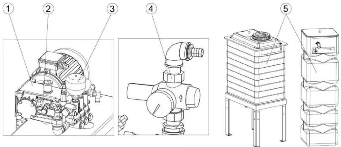
System description
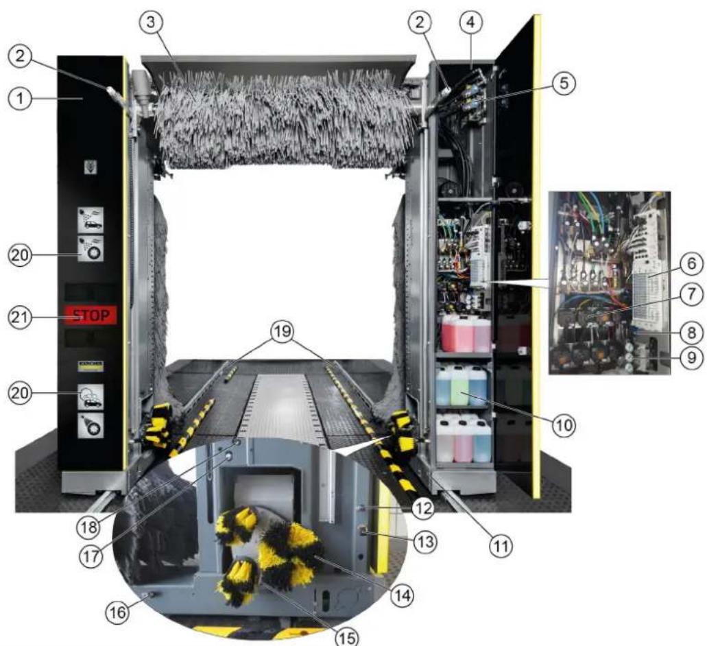
Overview of the entry side of the system
text_image
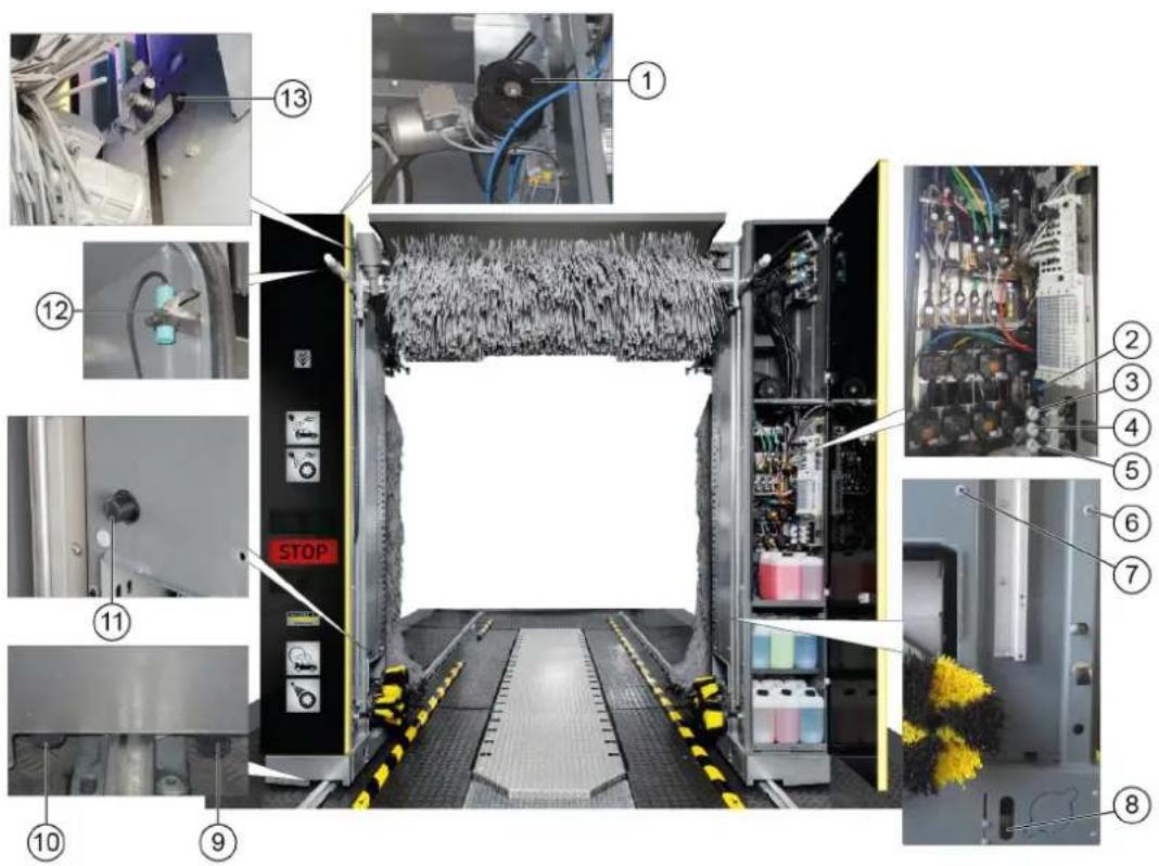
Technical diagram of an industrial control unit with numbered components and close-up views of internal wiring and equipment.①Pillar 1
②Brush watering nozzles (circuits A1 / A2 / A3 optional instead of C3)
③ Roof brush
④Pillar 2
⑤High-pressure valves
⑥Pneumatic valve block
⑦ Dosing pumps
⑧ Maintenance unit
⑨Pressure reducer
⑩Cleaning and care agents
⑪ Chassis and suspension
⑫ Nozzles for fresh water, chemical drying aids, wax (circuit A1)
⑬ Nozzles for wheel rim foam/prespraying of wheel rims
⑭ Wheel washing unit
⑮High pressure nozzles for wheel washer/wheel well cleaning
⑯ Nozzles for foam, insects, intensive Basic (circuit B2)
⑰Nozzles for processed water, shampoo (circuit B1)
⑱High-pressure nozzles
19 Guide rails
⑳ Washing phase display
②1 Positioning light
Overview of the exit side of the system
text_image
Diagram of a car cleaning or snow-making machine with numbered components and labeled parts, showing structural components and assembly.①Side brush 2
② Roof brush
③ Nozzles for polishing (circuit C3)
④ Nozzles for fresh water, chemical drying aids, wax (circuit C2)
⑤ Nozzles for processed water, shampoo (circuit C1)
⑥Roof blower motor
⑦Side brush 2 rotation motor
⑧ Roof drier
⑨Side brush 1 rotation motor
⑩Side brush 1
Standard equipment
Side brushes
The rotating side brushes clean the vehicle at the sides, front and rear.
Roof brush
The rotating roof brush removes dirt from the top of the vehicle.
Wheel washing unit (circular broom)
The washing bay is equipped with two wheel washing units for thorough wheel cleaning. The position of the wheels is determined by a light sensor.
The rotating brushes are pressed against the wheel rim by pneumatic cylinders.
The brushes are watered by a nozzle mounted in the centre of each brush.
Note
An optional height-adjustable wheel washing unit is available.
Nozzles and spray arches
Processed water and fresh water is sprayed onto the vehicle by nozzles and spray arches.
Cleaning agents and care agents are mixed into the water according to the washing program.
text_image
C3 C2 C1 H4 B2 B1 H3 L K G H2 A2 A1 A3A1 = Fresh water, chemical drying aid (CTH), wax
A2 = Processed water, shampoo
A3 = Polishing (optional, instead of C3)
B1 = Processed water, shampoo
B2 = Foam, insects, intensive Basic
C1 = Processed water, shampoo
C2 = Fresh water, chemical drying aid (CTH), wax
C3 = Polishing
G = Prespray wheel rims
L = Tar remover
K = Wheel gloss
H 2 = High pressure wheel wash
H 3 = High-pressure side nozzles
H4 = High-pressure roof nozzles
Foam wash
The cleaning agent for pre-cleaning is applied as a foam to extend the contact time.
Dirt traps
The dirt traps retain particles that might clog the nozzles.
Dosing pumps
The dosing pumps mix cleaning and care agents into the water.
Dryer side nozzles
The air required for blowing the sides of the vehicle dry flows out of the drier nozzles.
Roof drier
The drier blower bars are moved along the contour of the vehicle. The air flow required for drying the vehicle is generated by integrated fans.
Positioning light
The positioning light has the following functions:
- For positioning the vehicle before washing.
- For indicating the exit direction after washing.
- For indicating faults.
Light sensors
The light sensors provide the following information:
• The position and contours of the vehicle.
• The position of the vehicle wheels.
Cleaning and care agents
The cleaning and care agent canisters and dosing pumps are located in pillar 2.
A maximum of 8 canisters can be installed in pillar 2.
The supply can be optionally provided from the technical room if more canisters are required.
The suction hoses, canisters and dosing pumps are all labelled with the same colour Labelling of the dosing pumps.
| Name D | Description Consump- | tion | Order no. |
| RM 896 | Vehicle Pro Klear! RIM* 15-2 | 5ml 6.296-0 | 77.0 |
| RM 890 | Vehicle Pro Klear! Prewash* | 10-14ml 6.2 | 96-003.0 |
| RM 891 | Vehicle Pro Klear! Brush* 7-1 | 10ml 6.295-9 | 95.0 |
| RM 892 | Vehicle Pro Klear! Foam* 8-1 | 10ml 6.295-9 | 98.0 |
| RM 893 | Vehicle Pro Klear! Dry* 8-12 | ml 6.296-00 | 1.0 |
| RM 894 | Vehicle Pro Klear! Glow* 10- | 15ml 6.295-9 | 993.0 |
| RM 837 | Vehicle Pro Klear! Plus** | 15ml | 6.295-779.0 |
* Container capacity 10 litres
* Container capacity 20 litres
Type plate
The major device information is specified on the type plate.
Control cabinet
The system control cabinet is located at the main supply distributor.
Supply distributor
The main switch for the system is located on the main supply distributor.
The main supply distributor is located outside the washing bay, in the technical room or at suitable location in the vicinity of the washing bay.
text_image
① ② ③① Supply distributor
②Key switch, see ABS payment system
-0 = System off
- 1 = Operation via wash card reader
- 2 = Operation via wash card reader and control panel (display)
③ Main switch, see Main switch
Emergency off
In the event of danger to persons, equipment or animals, the system must be switched off immediately by pressing the "EMERGENCY OFF" button.
"EMERGENCY OFF" buttons are located:
- On the wash card/code reader.
- On the control panel.
- Optionally at the washing hall entrance if the control panel or wash card/code reader are not located at the entrance.
Operating station
The washing bay is supplied with:
• A control panel with display
• A wash card/code reader (optional)
Tilt protection
A mechanical retainer keeps the system on the guide rails, even in the case of incorrect behaviour by the washing customer.
Options
Wash card reader/code reader
A wash card reader or code reader is used for operating the washing bay in self-service mode.
Note
The wash cards/codes required for operating the system are programmed on the respective system.
Process water connection
The process water connection allows rain water or recycled water to be used as a partial replacement for fresh water.
Planet wheel washing unit
The planet wheel washing unit is equipped with 3 brushes instead of a circular broom.
Height-adjustable wheel washing unit
The wheel washing units can be additionally equipped with a height adjustment mechanism.
Wheel well cleaning
The wheel wells and sills of the vehicle are cleaned by water jets from 2 additional nozzles per washing direction.
Underbody washing unit
The vehicle underside can be washed with the underbody washing unit. For this, water is sprayed at high pressure over the entire underbody via two pivoting nozzle pipes.
Prespraying (remove insects)
Foam is applied to the front half of the vehicle by the prespraying nozzles. The foam is generated from water, prespraying agent and compressed air.
Intensive Basic
Pre-cleaning chemicals are applied to the vehicle by stationary nozzles.
The foam is generated from water, prespraying agent and compressed air.
Wheel rim foam
Compressed air is used to spray a water-cleaning agent mixture onto the wheel rims via 2 stationary foam nozzles.
High-pressure wash
The high-pressure wash removes coarse dirt from the surface of the vehicle. High-pressure cleaning minimises the danger of scratching from sand grains or similar abrasives and makes a significant contribution to preserving the paintwork during cleaning. Various different versions are available:
• Working pressure 16 bar (1.6 MPa)
• Working pressure 60 bar (6 MPa)
- Working pressure 70 bar (7 MPa), on-board high-pressure pump (in the portal)
Foam wax
Foam wax is applied to the vehicle by the drying aid nozzles before the drying process.
Cold wax
Water mixed with wax is sprayed onto the vehicle via the cold wax nozzles. Two different types of cold wax (wax 1 and wax 2) can be selected.
Cleaning agent heater
The cleaning agent heater is located in the cleaning agent supply in pillar 2.
Frost protection device
The washing bay can be equipped with a frost protection device: If there is a danger of frost, the water is blown out of the piping system automatically.
This blowing process is controlled by a thermostat.
Reverse osmosis system
Demineralised water (from an on-site system or optionally available reverse osmosis system) or fresh water dosed with drying aid is sprayed onto the vehicle via the drying aid nozzles.
Foam polishing
A compressed air foamed mixture of water and cleaning agent is sprayed onto the vehicle via 2 stationary nozzles. This is followed by a polishing procedure with the washing brushes.
Safety switch
Safety switches are required if the required safety clearances between the washing bay and permanent fixtures (e.g. walls, pillars, sinks) cannot be maintained. The safety switches prevent persons from being crushed between the system and the wall.
The washing bay stops immediately if a safety switch touches an obstacle.
Note
If the system is stopped by a safety switch, determine the cause if this hand have the safety switch reset by an authorised technical specialist.
Splash guard
The splash guard protects the areas adjacent to the washing station from sprayed dirt and splash water emitted by the rotating side brushes.
The splash guard is attached to the outer surfaces of the chassis and suspension as well as the pillars.
Bollard protection
The purpose of the bollard protection is to ensure central alignment of the vehicle. They prevent the vehicle from being parked too far away from the centre.
Remote reset
The Reset function allows the wash gantry to be moved to the initial position remotely with a command via an interface. The function can be enabled via a separate parameter in the system control.
- This function must only be enabled in countries or at locations where this function is permitted.
- Video surveillance must be installed on site, covering the entire area of the washing hall or the entire travel path of the system, and any regulations applicable in the country/municipality where the system is installed must be applied.
- The person who performs the remote reset must first ensure via the video surveillance that there are no persons in the travel path of the system. If a person then requests the command, that person must confirm that the system and its travel path are completely free by acknowledging a safety notice (e.g. pop-up window).
- The person who integrates the system into his system, e.g. via the Internet, is responsible for the required security or cybersecurity and a risk assessment must be carried out on the system.
Gate control
The on-site gate control is actuated by the passenger vehicle portal controller with the correct signals according to the washing sequence.
A distinction is made between summer gate control and winter gate control.
Summer gate control
- The gates are open before washing starts.
• The vehicle can drive in.
• The gates are closed when washing starts. - The gates are opened when washing ends and remain open.
Winter gate control
- The entry gate is closed before washing starts and must be opened to allow the vehicle to drive in. This is done by e.g. inserting a wash card into the wash card reader.
- The gates are closed when washing starts (e.g. by pressing the "Start" button on the wash card reader).
- The gates are opened when washing ends and are closed again after the vehicle has exited.
Control elements
Emergency off
In the event of danger to persons, equipment or animals, the system must be switched off immediately by pressing the "EMERGENCY OFF" button.
"EMERGENCY OFF" buttons are located:
- On the wash card/code reader.
- On the control panel.
- Optionally at the washing hall entrance if the control panel or wash card/code reader are not located at the entrance.
Main switch
The main switch is located at the main supply distributor.
Set the main switch to "1" to switch the system on.
ABS payment system
At the key switch on the main supply distributor, see Supply distributor can be used for selecting the operating stations from which washing programs can be started.
- Position 0: Programme start not possible
- Position 1: Programme start possible at the wash card/code reader
- Position 2: Programme start possible at the wash card/code reader and at the control panel
Wash card/code reader
Depending on the version of the Wash card/code reader, the washing program can be selected as follows:
- Entry via a keypad.
• The program specified on the wash card.
• Entry of a code number.
Note
Further information is provided in the separate operating instructions for the wash card/code reader.
Control panel
text_image
07.04.2018 10:07:02 ① ② ③①Emergency off button
②Display
③Control voltage/initial position button
Dosing pumps
The cleaning and care agents are added to the water by the dosing pumps located in pillar 2.
The assignment of the dosing pumps is by way of example only. Dosing pumps 1-4 are assigned as shown in a standard system. 7 different cleaning and care agents can be selected for dosing pumps 5-8.
text_image
Electrical control panel with numbered components and labeled switches, wires, and meters①Dosing pump
②Shampoo dosing pump
③Foam dosing pump
④Wax 1 dosing pump
⑤Pre-cleaning dosing pump (insects)
⑥ Wax 2 dosing pump
⑦Wheel cleaner dosing pump (wheel rim foam)
⑧Polishing dosing pump
The dosing pumps add cleaning and care agents to the washing water according to the washing program and the equipment in the system.
Note
The dosing quantities are adjusted optimally by the installation technician during initial commissioning. Changes to these settings are not usually necessary.
Labelling of the dosing pumps
Note
The positioning of the dosing pumps is system-dependent.
| Dosing pump | Cleaning and care agents |
 | Drying aid |
 | Shampoo |
 | Active foam |
 | Wax 1 |
 | Polish 1 |
 | Wheel cleaning |
 | Wax 2 |
 | Tyre gloss |
 | Insect pre-cleaning |
 | Polish 2 |
 | Intensive Basic |
Adjusting the dosing amount

text_image
1 2 3 3 Voh①Venting button
②Venting lever
③Dosing amount adjustment knob
ATTENTION
Damage to the dosing pump due to dry running
Only adjust the dosing amount when the dosing pump is running.
- Pull out the dosing amount adjustment knob.
- Alternately press and release the ventilation button while turning the adjustment knob to the desired setting.
- Release the ventilation button.
- Press in the dosing amount adjustment knob.
Vent the dosing pump
The system compressed air supply must be in operation.
text_image
1 2 3 3 kWh FORCHNER®① Venting button
②Venting lever
③Dosing amount adjustment knob
- Turn the venting lever anticlockwise as far as it will go.
- Set the dosing amount to 100%.
- Press the ventilation button repeatedly until the detergent comes out of the venting line on the underside of the dosing pump without bubbles.
- To set the dosing amount back to the desired value, see Adjusting the dosing amount.
- Turn the venting lever clockwise as far as it will go.
Display description
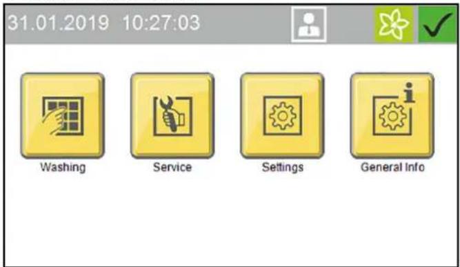
Start display
31.01.2019 10:27:03


Washing
Service
Settings
General Info
Note
The language is set during initial commissioning and can be changed via the Settings / General menu.
The display can be used for e.g. making system settings, making settings for the display and displaying system information.
Status bar
① ② 07.06.2018 10:04:08
③ ④ ⑤ ⑥
①Date
②Time
③Currently logged-in user
④ Service date is due
⑤Current season (if this function is enabled)
⑥Current system status
Description of symbols
The following symbols are shown on the display, depending on the current menu or status of the system

System ready for operation
System malfunction
Home button

The Home button us used to navigate back to the previous menu from a submenu.

Logged in with normal User access rights

Logged in with Cleaning agent supplier access rights

Logged in with Operator access rights

Logged in with Service access rights
Spring seasonal washing program set

Summer seasonal washing program set

Autumn seasonal washing program set
Winter seasonal washing program set
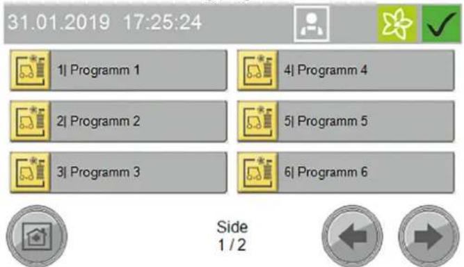
Washing
The Washing menu is used for selecting and starting programs and additional programs.
The currently running program can be interrupted and the progress in percent can be displayed.
31.01.2019 17:25:24


1| Programm 1

4| Programm 4

2| Programm 2

5|Programm 5

3| Programm 3

6|Programm 6

Side 1/2


Start washing program, see Start the program on the display.
Service
The Service menu allows manual functions to be executed and the manual frost protection device to be started.
31.01.2019 12:23:28


Manual Operation
Diagnosis

Service
The Service menu contains the following submenus:
- Manual mode (portal manual functions, manual starting of the frost protection device, manual water system functions)
- Diagnostics (Operators and Service personnel only) This calls up self-test functions for the system
Settings
The Settings menu contains the user management functions and allows system settings to be made.
31.01.2019 11:57:35


User Administration
Wash-Program Settings
Machine
General

Settings
The Settings menu contains the following submenus:
- User administration
- Wash program settings (pre-cleaning portal speed, brushes, care and drying, seasonal settings)
- System (cleaning agent, water supply, gate operation, customer text priority display)
- General (set date, time and opening times, select language, display system information)
General Infos
This menu can be used for displaying system reports and showing the current filling levels of the cleaning agents.
31.01.2019 17:18:35


Wash-Counter

Operating Hours
Maintenance Diagnostic
Liquid Level Detergents

General Info
The General Info menu contains the following submenus:
- Wash counter (Operators only) - display of the completed and interrupted washes
- Operating hours
- Maintenance diagnostics - interval to the next servicing, system information, error memory, event memory
- Cleaning agent filling levels - percentage filling levels of the cleaning agents (option)
Messages on the display
The following push messages can be shown on the display when the system is in operation.
Critical fault
Critical fault
SB2 Position not logical
Endpos. In-Out Simultaneous
Check Limit Switches
Inform Technical Service
F0212 31.01.2019 14:35:29

Message 2/2


△DANGER
Danger from a critical fault
Switch the system off and notify the Service department.
Critical faults may only be corrected by persons trained in the system servicing tasks.
If multiple errors are present, these are displayed one after another.
You can switch between the displays using the arrow keys.
Malfunction
Malfunction
Dryer LightbarrierMiddle
Lightbarrier Blocked
Check, Clean Lense
Malfunctions are errors occurring during the washing program. The washing program is interrupted and can be resumed after elimination of the malfunction.
If multiple malfunctions are present, these are displayed one after another.
You can switch between the displays using the arrow keys.
A detailed description of troubleshooting is provided in chapter Troubleshooting guide.
Event
Event
Position Right Wheelwasher
Not In Initial Position
Stroke Mechanisum, Air Supply
Reset (Blue Button)
E5017 31.01.2019 14:24:48

Message
2/2


An event is an error occurring when no washing program is active.
If multiple events are present, these are displayed one after another.
You can switch between the displays using the arrow keys.
A detailed description of troubleshooting is provided in chapter
Troubleshooting guide.
System not in initial position
31.01.2019 17:09:45


Machine Not In
Initial Position
Press Button To
Return Machine Into
Home Position

This message appears when one or more power units are not in their respective initial position.
Note
Press and hold the button (> 2 seconds) or press and hold the blue button (> 2 seconds) to move the system to the initial position.
Service required
31.01.2019 13:42:22


Service Intervall
Reached
Please Scedure
Maintenance

This message appears when a service date is due.
Note
Contact the Service to arrange a servicing appointment.
Start-up
-
Open the stop valves for water and compressed air.
-
Set the main switch at the main supply distributor to "1".
-
Press the blue control voltage/initial position button on the control panel.
System ready for operation. The vehicle to be washed can now be driven in.
Operation
△DANGER
Danger from moving system components
Switch the system off immediately using the emergency off button in the case of danger to persons, property or animals.
ATTENTION
Risk of damage to the vehicles through inadequately removed cleaning agent
If a malfunction occurs in the washing bay after application of the cleaning agent, you must remove the cleaning agents by spraying thoroughly with water after switching off the system to prevent paint damage due to an excessively long cleaning agent exposure time.
Note
In self-service systems, a person must always be available during operating periods who is familiar with the washing system and can take or initiate the measures necessary for preventing potential dangers.
Switching on again after an emergency off
Note
Correct the reason for actuating the emergency off button before switching the system on again.
Persons or animals must not be present in the work area. Any vehicles present must be driven out of the system.

text_image
19:04.2018 10:07 G2 Watchbox Sensors Exhaust engine Abgustaining index ① ②①Emergency stop button
②Control voltage/initial position button
1. Unlock the emergency off button by pulling it.
2. Press the blue control voltage/initial position button on the control panel.
In the initial position, the upper green "Forwards" lamp on the positioning light lights up. The system is now ready for operation, the vehicle to be washed can now be driven in.
Log in the user on the display
- Select Settings/User Administration in the main menu.
The available users are displayed.
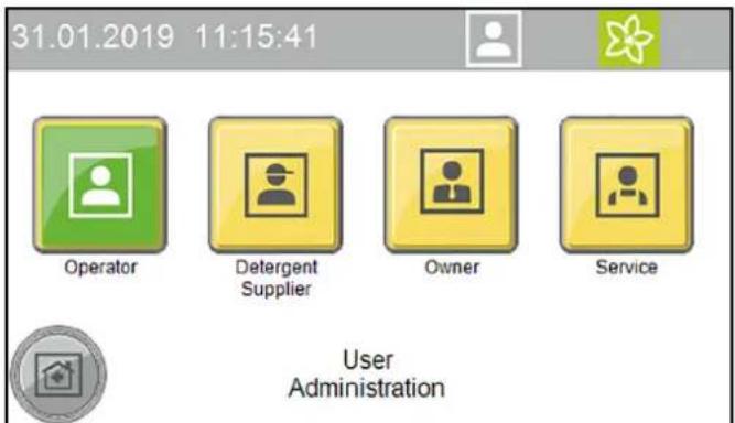
text_image
31.01.2019 11:15:41 Operator Detergent Supplier Owner Service User Administration- Select the desired user.
The dialogue for entering the code opens.
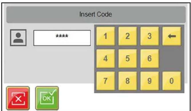
text_image
Insert Code **** 1 2 3 4 5 6 7 8 9 0- Enter and confirm the code.
The symbol for the currently logged-in user is displayed in the top line.
Note
The user level switches automatically back to the normal User level after 30 minutes of inactivity.
Preparing the vehicle
ATTENTION
Damage to the system and the vehicle
To prevent damage to the vehicle, take care to ensure that the following measures are taken before starting the system.
- Close all windows, doors and sunroofs.
- Push in the antennas, fold them in towards the rear or remove them.
- Fold in any large or wide projecting mirrors.
-
Check the vehicle for any loose vehicle parts and remove these, e.g.:
-
Trim strips
- Spoiler
- Bumpers
- Door handles
- Exhaust pipes
● Wind deflectors - Tarpaulin ropes
- Rubber seals
● Externally mounted sun visors - Luggage racks
Driving in the vehicle
The positioning light assists the customer in positioning the vehicle correctly.
text_image
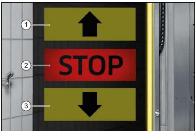
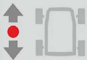
① ↑ ② STOP ↓ ③①Drive forwards
②Stop, position OK
③Drive in reverse
- Position the vehicle straight ahead and centrally between the guide rails.
After positioning
- Shut down the engine.
- Engage one gear.
- With an automatic transmission, select "P".
- Apply the handbrake.
- Check that all instructions from Preparing the vehicle have been followed.
- Exit the vehicle (all persons).
- Start the washing programme depending on the start type.
Starting the program
At the wash card/code reader
Note
Operation with a wash card/code reader is described in the separate operating instructions for the wash card/code reader.
Start the program on the display
- Press the "Wash" button.
text_image
31.01.2019 10:27:03 Washing Service Settings General Info- Select the desired washing program.
text_image
31.01.2019 17:25:24 1| Programm 1 2| Programm 2 3| Programm 3 4| Programm 4 5| Programm 5 6| Programm 6 Side 1 / 2- Select the desired options and confirm with "OK".
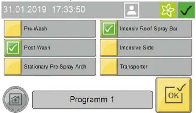
text_image
31.01.2019 17:33:50 Pre-Wash Post-Wash Stationary Pre-Spray Arch Intensiv Roof Spray Bar Intensive Side Transporter Programm 1- Start the washing program.
Start Wash Programm
Press START


natural_image
Two gray icons: one with a red dot and arrow, the other with a car outline (no text or symbols)- The following manual functions can be executed via the display while a washing program is running:
text_image
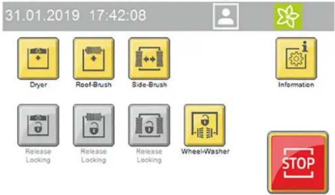
31.01.2019 17:42:08 Dryer Roof-Brush Side-Brush Information Release Locking Release Locking Release Locking Wheel-Washer STOPa Lock/raise dryer
b Lock/raise roof brush
c Lock/outwards movement of the side brushes
d Stop the wheel brushes
Press the "Information" button to show the program progress display.
Interrupting the currently running program

- Press the "Stop" button.
The program is interrupted.

- Press the "Start" button to resume the program.
Programme end
After the programme has finished, the positioning light indicates whether the vehicle should be driven forwards or backwards out of the system.
- Drive the vehicle out of the system.
Manual mode
Manual functions can be performed with the following assemblies:
- Portal - move
• Roof brush - raise and lower, switch on and off - Side brushes - move in and out, switch on and off
- Dryer - raise and lower, switch on and off
-
Wheel brushes - move in and out, switch on and off
-
Select Service / Manual mode / Manual portal in the main menu.
The menu with executable manual functions opens.
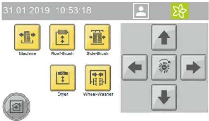
text_image
31.01.2019 10:53:18 Machine Roof-Brush Side-Brush Dryer Wheel-Washer- Select the desired assembly.
The executable manual functions are shown in yellow.
- Start the manual function.
The selected assembly must be deselected before selecting another assembly.
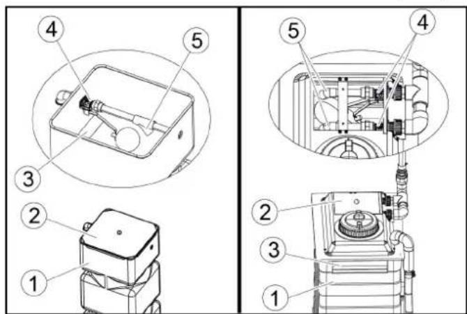
Refilling the cleaning and care agents
⚠ WARNING
Danger due to chemicals
Observe the safety data sheets for the cleaning and care agents used.
Note
Press the "General Infos" and "Cleaning agent filling levels" buttons on the display to display the filling levels", see General Infos.
The filling level display is an optional extra.
natural_image
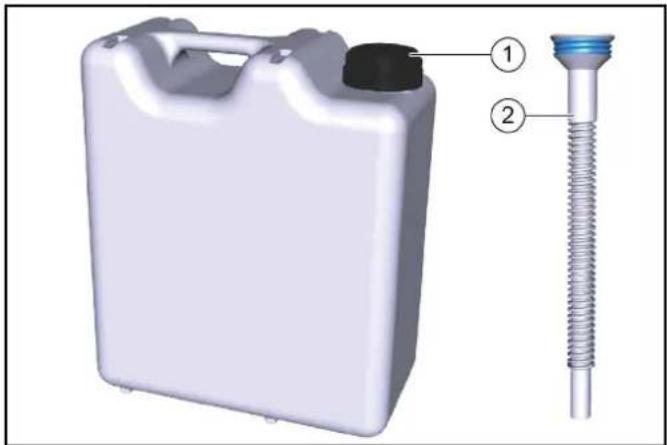
3D rendering of a white plastic container with a black cap and threaded spring, labeled with parts 1 and 2 (no text or symbols on the main subject)①10 litre refill canister
②Overflow pipe
- Screw the refill canister onto the overflow pipe.
- Open the corresponding cleaning or care agent container.
- Fill the reservoir and close it again.
Shutting down
Short-term shutdown
- End a currently running washing programme.
- Leave the main switch set to "1" so that the optional frost protection device can remain activated.
Long-term shutdown
- End a currently running washing programme.
- Drain all water lines if frost is to be expected during the shutdown period.
- Set the main switch to "0".
- Close the water supply line.
- Close the compressed-air supply line.
- Remove the detergent and care agents.
Shutdown via the automatic frost protection device (optional)
ATTENTION
Damage to the system if the frost protection device is not switched on
If frost is to be expected, take care to ensure that the main power switch is switched on and no emergency stop buttons are actuated. The following steps are performed automatically when the temperature falls below the minimum temperature:
- The currently running washing program is executed until finished.
- After the washing program has finished, the hoses and nozzle pipes of the portal are blown out with compressed air.
- Starting of further washing programs is locked out.
Note
The system is automatically ready for operation after the danger of frost has passed
Manually starting the automatic frost protection process
ATTENTION
Damage to the system through temperatures below zero Execute the frost protection process for the system.
Note
In systems with an automatic frost protection unit, the frost protection starts as soon as the preset temperature is reached.
31.01.2019 12:34:01


Manual Operation Machine
Manual Operation
Frost Protection
Manual Operation Water

Manual Operation
- Select Service / Manual mode in the main menu.
- Press the "Manual frost protection" button to start the frost protection process.
The frost protection process starts and the time remaining is shown in the display.
31.01.2019 13:24:34


60 °C
00:25:17

Manual Operation
Frost Protection
Care and service
Maintenance instructions
Regular maintenance according to the following maintenance plan is fundamental for a safely operating system.
△WARNING
Risk of injury from machine movements
Switch the system off before performing maintenance and servicing work.
Secure the main switch with a padlock to prevent it from being switched on again.
△WARNING
Risk of injury from pressurised compressed air reservoirs and lines after the system has been switched off
Depressurise the system before performing any work on the system.
Check the pressure gauge at the maintenance unit to ensure that the system is depressurised.
△WARNING
Risk of injury from the high-pressure system after the system has been switched off
Depressurise the high-pressure system before performing any work on the system.
△DANGER
Risk of injury from escaping compressed air, high-pressure water at nozzle outlets and propelled dirt particles or similar in the vicinity of the rotating brushes!
Dirt particles or loose objects can injure persons or animals when propelled off the vehicle.
Compressed air or high-pressure water can remain pressurised even when the system is switched off.
Keep the hall floor free of loose lying objects.
Exercise care when operating the compressed air system and the high-pressure system.
Wear suitable safety goggles when performing maintenance work.
Target groups for care and maintenance
Who is permitted to perform inspection, maintenance and servicing work?
Operator
Work labelled with "Operator" may only be performed by instructed persons who are capable of safely operating and maintaining the system.
Customer Service
Work labelled with "Customer service" may only be performed by Kärcher customer service technicians or Kärcher-authorised installation technicians.
Service contract
We recommend that you close a service contract to ensure reliable operation of the system. Please contact your KÄRCHER customer service department responsible.
Preparation
For you own safety and the safety of others, the system should be switched off when performing maintenance and servicing work. Since not all system components requiring maintenance are freely accessible, some system components must be moved during maintenance and servicing work. The "Manual mode" operating mode is provided for this.
The manual mode is executed on the display.
△DANGER
Risk of injury
Take care to ensure that you perform the following work steps only in the specified sequence.
ATTENTION
Risk of damage due to Manual mode
Do not use the Manual mode for washing vehicles.
- Drive any vehicle present out of the system.
- Ensure that no persons or animals are present in the system.
- Switch on the system.
- Select manual mode on the display.
- Move the system components.
- Switch off the system and secure it against being switched on again.
- Perform the maintenance and servicing work.
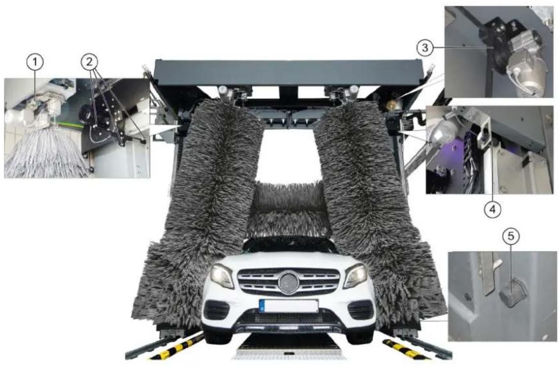
Front portal maintenance overview
text_image
Technical diagram of an industrial control room with numbered components and labeled parts, including a stop unit and electrical equipment.①Roof brush drive belt and belt pulley
② Maintenance unit
③Side brush tilt pressure reducer
④Side brush lock pressure reducer
⑤Wheel wash pressure reducer
⑥ Vehicle position 1 light sensor
⑦ Vehicle position 2 light sensor
⑧Wheel detection light sensor
⑨Portal movement start limit switch
⑩ Portal movement end limit switch
⑪Lower roof brush limit switch
⑫Pillar 1 door switch limit switch
⑬ Upper roof brush limit switch
Rear portal maintenance overview
text_image
Technical diagram of a car cleaning or maintenance system with numbered components and close-ups of mechanical components.①Side brush steering overload switch
② Roof drier light sensors
③Roof drier drive belt and belt pulley
④ Upper roof drier limit switch
⑤Lower roof drier limit switch
Hall maintenance overview
natural_image
Close-up of a metal pipe joint with two circular components, no visible text or symbols
natural_image
Close-up of concrete structural beams and a small circular component with two rings, no visible text or symbols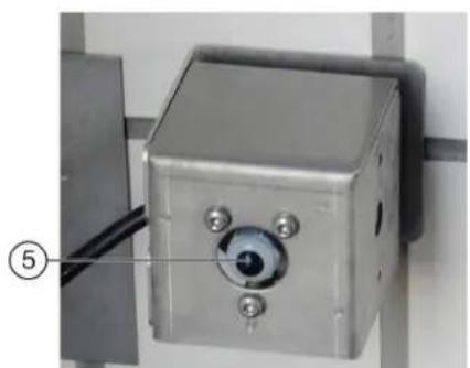
natural_image
Close-up of a metallic industrial control box with a circular eye and three screws, mounted on a wall (no visible text or symbols)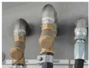
natural_image
Three industrial pipe fittings with brass and metallic components, no visible text or symbols④ ③
①Portal exit end position mechanical limit stop
②Portal entry end position mechanical limit stop
③Fresh water dirt trap
④Processed water dirt trap
⑤Hall entry and exit light sensors
Machine room maintenance overview
text_image
Technical diagram of a mechanical device with numbered parts and exploded views, including a cylindrical component and stacked storage unit.①High-pressure pump
②Oil level indicator
③Pressure tank
④Pressure reducer
⑤Fresh water tank
Daily maintenance plan
| Assembly Activity Performed Target group | |||
| Emergency off buttonSafety switch | Check Start the washing program | am, actuate an emergency-offbutton or safety switch, the system must stop immediately, then switch the system on again, see chapter “Switching on again after an emergency off”. | Operator |
| Signs with operating instructions and intended use | Check the instructions for self-service customers (self-service systems only) | Check all signs for completeness and legibility.Replace any damaged signs. | Operator |
| Cleaning and care agent reservoirs | Check the filling level | Refill or replace as necessary. | Operator |
| High-pressure hoses from the high-pressure pump to the washing bay | Check Check the hoses for damage. | Replace faulty hosesimmediately. Danger of accident. | Operator |
| Spray nozzles/sieves | Checking for clogging | Visual inspection (assess the spray pattern), clean if necessary. | Operator |
| Eliminate clogging Warning, do not swap over the nozzles.Unscrew nozzles individually to avoid mixing them up.Clean with compressed air or insert in a detergent solution and then clean with a brush or needle. Screw in the nozzles again. | Operator | ||
| Light sensors | Check for soiling, clean if necessary | For light soiling, wipe the light sensors with a damp cloth without detergent under light pressure. In the event of heavy soiling, spray the cloth with a gentle detergent. | Operator |
| Limits switches | Visual inspection | Check for mechanical damage and firm seating. | Operator |
| Side brushes, roof brush, wheel brushes | Check for foreign bodies | Visual inspection, remove any foreign bodies, clean dirty brushes with a high-pressure cleaner. | Operator |
| Rinsing and spray circuits | Check the water supply | In washing mode, check that sufficient water for vehicle washing is available.Too little water of no water can damage the vehicle being washed. | Operator |
| Positioning light | Function test | Interrupt the “Position 1” and “Position 2” light sensors, for the position of the light sensors see chapter “Front maintenance overview”.The positioning light must display corresponding signals. | Operator |
Weekly maintenance plan or after 500 vehicle washing hours
| Assembly | Activity | Rectification | Target group |
| Roof brush rollersSide brush rollers | Visual inspection Check the true running of the brush shaft.Check the brushes for tight seating.Check the brush for wear and tear.Minimum bristle length = as-new length minus 50 mmReplace the brushes if necessary. | Operator | |
| Supply line hoses and pipeline Visual inspection Check for leaks. | Operator | Customer Service | |
| High-pressure pump(s) Checking for leaks Check pump and line | system for leaks. Notify Customer Service if you lose oil or if there is a leak of more than 10 drops of water per minute. | Operator | |
| Checking the oil level Target level in the middle of the oil level indicator. Top up with oil if necessary (order no. 6.288-020.0) and inform Customer Service immediately. | Operator | ||
| Check pressure tank If there is increased vibration in the high-pressure pump, the pressure tank is defective. Contact Customer Service. | OperatorCustomer Service | ||
| Fresh water tank | Check the float switch | Check the function of the float valve (see "Maintenance work"). | Operator |
| Operating station with display | Cleaning/Care | Wipe the surface with a damp cloth, spray the cloth with a detergent and clean it if heavily soiled | Operator |
| Panel/glass front system | Cleaning | Spray the surface with an acidic cleaner and clean with a soft pad, then rinse with clean water and remove with a squeegee | Operator |
Maintenance plan after 1000 washes
| Assembly | Activity | Performed | Target group |
| Check the running rollers of the side brush rollers | Visual inspection Check the p | play by moving the side brushes.Contact Customer Service in the case of excessive play between the carriage and guide. | OperatorCustomer Service |
| Screws on the guide rails for the roof brush and roof drier | Re-tighten | Check for tight seating of the screws and tighten if necessary.Tightening torque 25 Nm | OperatorCustomer Service |
Monthly maintenance plan after 2000 washes
| Assembly | Activity | Rectification | Target group |
| Maintenance unit | Cleaning the filter | Shut off the compressed air supply and then extend and retract the wheel washing unit in manual mode until the system is depressurised.Check the pressure gauge to ensure that the system is completely depressurised.Unscrew the filter housing, remove the filter insert, clean the filter with compressed air, fit the filter, screw the cover on again. | Operator |
| Processed water and fresh water dirt trap | Cleaning | Shut off the water supply, unscrew the cover of the dirt trap, remove the filter, flush the filter with water, fit the filter again, screw on the cover. | Operator |
| Pressure reducer | Cleaning the sieve | See "Maintenance work". | Operator |
| Roof brush and roof drier | Visual inspection of the drive belts | Check the condition of the drive belts and replace if necessary. | Customer Service |
| All limit switches | Check the fasteners and clearances4 | Check the clearance between the limit switch and switching vane using a feeler gauge.If necessary, adjust the limit switches by adjusting the plastic nuts.Limit switch clearances:∅30 mm = 5.0 mm∅30 mm = 2.0 mmSide brush movement counter∅12 mm = 3.0/ ±0.1 mmRoof brush/drier lifting counter∅12 mm = 3.5/ ±0.1 mm | Customer Service |
| Washing hall | Cleaning | Spray the surfaces such as floor, walls and tiles with an acidic detergent, allow to take effect, clean off the detergent with a soft pad (white) | Operator |
Half-yearly maintenance plan or after 5000 washes
| Assembly | Activity | Rectification | Target group |
| Cables and hoses for:Energy pillar orenergy chain ortrailing cables | Visual inspection Condition of | the hoses and cables.Check the hoses and connecting elements for leaks. | Operator |
| Side brushes, roof brush, wheel brushes | Basic cleaning Spray the brus | hes with a detergent (pre-cleaner or hall cleaner), allow to act and rinse thoroughly with high-pressure cleaner and warm water at max. 40 °C | Operator |
Annual maintenance plan or after 10000 washes
| Assembly | Activity | Rectification | Target group |
| Self-service gantry Check the toothed rack for wear and tear | OperatorCustomer Service | ||
| Wheel washing brushes Visual inspection Replace the brushes after approx. 15000 washes.Replacing the wheel washing brushes: Remove the screws inside the brush ring, remove the wheel washing brush, fit the new wheel washing brush and fasten in place with the screws. | OperatorCustomer Service | ||
| High-pressure unit Safety check Carry out a safety check according to the guidelines for liquid emitters. | Expert customer service | ||
Maintenance work
Clean the pressure reducer strainer
- Close the water inlet.
- Unscrew the cover.
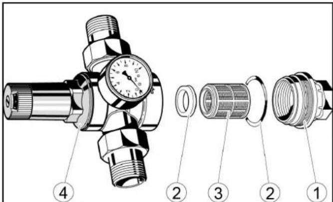
text_image
Technical diagram of a pressure regulator assembly with numbered parts for identification①Cover
②Seal
③ sieve
④Pressure reducer
- Take out the strainer and rinse it with water.
- Insert the sieve into the pressure reducer. Ensure that the seals are seated properly.
- Screw in and tighten the cover.
Check the float switch
- Check whether water comes out from the overflow opening.
text_image
Technical diagram showing exploded and assembled views of a mechanical device with numbered components①Fresh water tank
② Cover
③Overflow opening
④Float valve
⑤Outlet
- Remove the fresh water tank cap.
- Check whether the float valve closes completely when the fresh water is full.
Note
When the float valve is completely closed, no water comes out of the outlet.
4. Replace the cover.
Troubleshooting guide
△WARNING
Risk of injury from machine movements
Switch the system off before performing maintenance and servicing work.
Secure the main switch with a padlock to prevent it from being switched on again.
△WARNING
Risk of injury from pressurised compressed air reservoirs and lines after the system has been switched off
Depressurise the system before performing any work on the system. Check the pressure gauge at the maintenance unit to ensure that the system is depressurised.
△WARNING
Risk of injury from the high-pressure system after the system has been switched off
Depressurise the high-pressure system before performing any work on the system.
Target groups for troubleshooting
Who is permitted to eliminate faults?
Operator
Work labelled with "Operator" may only be performed by instructed persons who are capable of safely operating and maintaining the system.
Qualified electricians
Qualified electricians are persons with professional electrotechnical training and qualifications.
Customer Service
Work labelled with "Customer service" may only be performed by Kärcher customer service technicians or Kärcher-authorised installation technicians.
Fault messages on the display
Note
The faults, causes and remedies are shown in plain text on the display.
Critical fault
SB2 Position not logical
Endpos. In-Out Simultaneous
Check Limit Switches
Inform Technical Service
F0212 31.01.2019 14:35:29

Message 2/2


Eliminate the malfunction according to the message on the display and then acknowledge via the OK button.
Displays on the positioning light
| Display Blink | code | Cause Remedy | ||
| Blink-ing al-ternatel y | Manual mode ac-tive | Message | ||
| lights up | Washing is running | Message | ||
| lights up | Washing stopped | Message | ||
| Blink-ing al-ternatel y | Error ac-tive | Correct the error | ||
| Blink-ing briefly | Emergen-cy-off ac-tive | Determine the cause and unlock the emergency-off button | ||
| lights up | Move in-to posi-tion | Drive the vehicle into position | ||
| lights up | Stop posi-tioning | Stop the vehicle | ||
| Display Blink | code | Cause Remedy | ||
 | lights up | Reverse the positioning | Reverse the vehicle | |
 | ↑ STOP ↓ | Blinking | Washing finished | Drive the vehicle out forwards |
 | ↑ STOP ↓ | Blinking | Washing finished | Drive the vehicle out backwards |
Faults that are not displayed
| Fault | Cause | Rectification | Person responsible |
| Inadequate cleaning efficiency | No cleaning agent or insufficient cleaning agentNo air pressure or insufficient air pressure in the supply lineWorn brushes | Check the cleaning agent filling level and refill if necessary, vent the dosing pump.Check the air pressure and adjust if necessary (0.6 MPa (6 bar) at the maintenance unit pressure gauge).Clean the cleaning agent intake filter, check the cleaning agent pipes for damage.Check the brushes and replace if necessary. | Operator |
| High-pressure pump does not reach pressure | Suction-side pipeline system leaking.Water shortage | Check the screw connections and hos-es.Eliminate water shortage. | Operator, Customer Service |
| The pressure gauge pointer of the high-pressure pump vibrates strongly | Pump sucking airPressure tank defective | Check suction line.Replace pressure tank. | Customer Service |
| The high-pressure pump safety valve opens | Clogged washing bay nozzles | Check, clean, replace nozzles. | Operator |
| Hose or high-pressure valves clogged | Remove clog. Customer Service | ||
| Too little water or no water coming out of the nozzles | Dirt trap cloggedInsufficient water pressureNozzle cloggedAir in the centrifugal pumpSolenoid valve or supply line clogged | Clean the dirt trapCheck the water supply pressure and pumpsClean the nozzles with compressed airVenting the centrifugal pump by loosening the bleed screwCheck the solenoid valves and supply lines (water and electricity) and repair if necessary | Operator |
| Water continues coming out of the nozzles after washing | Dirty solenoid valve | Clean the solenoid valves | Customer Service |
| Inadequate drying Too little or too much drying aidIncorrect drying aidNo air pressure or inadequate air pressure | Increase or reduce the dosageCheck the cleaning agent filling levelClean the intake filterVent the dosing pumpUse original drying aid from KärcherCheck that the drying blower is working correctly | Increase or reduce the dosageCheck the cleaning agent filling levelClean the intake filterVent the dosing pumpUse original drying aid from KärcherCheck that the drying blower is working correctly | Operator |
| The wheel washing brush does not rotate | The motor circuit breaker in the control cabinet has triggeredContact pressure too high | Check the motor circuit breaker in the control cabinetReduce the contact pressure at the wheel wash pressure reducer | Operator |
| The wheel washing brush extends slowly or not at all | No air pressure or inadequate air pressure | Check the air pressure and adjust if necessaryIncrease the contact pressure at the wheel wash pressure reducer | Operator, Customer Service |
| The wheel washing brush extends at the wrong position | Dirty light sensors | Clean the light sensors and check the settings if necessary | Operator |
| The brushes become dirty quickly | Shampoo dosage too low | Adjust the shampoo dosageCheck the water volume and adjust if necessary | Operator |
| The undercarriage wash nozzle pipes pivot too slowly/too quickly or not at all | No air pressure or inadequate air pressurePivoting unit heavily soiledChokes incorrectly adjusted | Check the air pressure in the supply line and adjust if necessaryClean the pivoting unitRe-adjust the chokes | Operator, Customer Service |
| The system cannot be switched on | Power supply fault | Ensure a fault-free power supply as specified in the connection values | Operator, qualified electrician |
Venting the centrifugal pump
- Loosen the bleed screw.
text_image
Technical diagram of a pump system with labeled components and an inset view showing internal components.①Centrifugal pump:
② Bleed screw
- If water comes out, screw the bleed screw in again.
Warranty
The warranty conditions issued by our relevant sales company apply in all countries. We shall remedy possible malfunctions on your appliance within the warranty period free of cost, provided that a material or manufacturing defect is the cause. In a warranty case, please contact your dealer (with the purchase receipt) or the next authorised customer service site.
(See overleaf for the address)
Technical data
| CW 3 / CW 5(CWB 3/1) | CW 3 / CW 5(CWB 3/2) | CW 3 / CW 5(CWB 3/3) | ||
| Plant dimensions | ||||
| Washing height mm 2100, 2200, 2300 2400, 2500, 2600 2700, 2800, 2900 | ||||
| Frame height mm 2900 3200 3500 | ||||
| Total height mm 2930, 3030, 3130 3230, 3330, 3430 3530, 3630, 3730 | ||||
| Frame width mm 3500 3500 3500 | ||||
| Total width of side brushes mm 4040 4040 4040 | ||||
| Total width of splash guard mm 4060 4060 4060 | ||||
| Frame depth/depth with rotating brushes | mm | 1600 / 2170 | 1600 / 2170 | 1600 / 2170 |
| Total length of short hall | mm 2070 2070 2070 | |||
| System width at mirror height | mm 2450 2450 2450 | |||
| System width in the wheel wash region | mm 2100 2100 2100 | |||
| Track width of guide rails | mm | 2550, 2700, 2800 | 2550, 2700, 2800 | 2550, 2700, 2800 |
| Hall width with safety clearance | mm 4500 4500 4500 | |||
| Washing brushes | ||||
| Side brush diameter | mm 975 | 975 | 975 | |
| Side brush rotary speed | 1/min | 107 | 107 | 107 |
| Roof brush diameter | mm 975 | 975 | 975 | |
| Roof brush rotary speed | 1/min | 127 | 127 | 127 |
| Portal speed | m/min | 0 - 24 | 0 - 24 | 0 - 24 |
| Electrical connection | ||||
| Mains voltage | V | 400 | 400 | 400 |
| Frequency | Hz | 50 | 50 | 50 |
| Power rating | kW | 10-16 | 10-16 | 10-16 |
| Controller maximum supply fuse | A | 35-50 | 35-50 | 35-50 |
| Water connection | ||||
| Nominal width | Inches | 1 | 1 | 1 |
| Flow pressure as per DIN 1988 (at 100 l/min) | MPa | 0,4 - 0,6 | 0,4 - 0,6 | 0,4 - 0,6 |
| Max. temperature | °C | 50 | 50 | 50 |
| Compressed air connection | ||||
| Nominal width | Inches | 1/2 | 1/2 | 1/2 |
| Pressure | MPa | 0,6 - 0,8 | 0,6 - 0,8 | 0,6 - 0,8 |
| Consumption/washing (without frost protection device, pro-gram-dependent at a vehicle length of 4.5 m) | I | 50 | 50 | 50 |
| Consumption with without frost protection, approx. | I | 700 | 700 | 700 |
| Determined values in acc. with EN 60335-2-79 | ||||
| Sound level, washing process with drying | dB(A) | 87 | 87 | 87 |
| Sound level, drying mode only | dB(A) | 91 | 91 | 91 |
| Sound level, high pressure module | dB(A) | 86 | 86 | 86 |
| Sound power, washing process with drying | dB(A) | 101 | 101 | 101 |
| Sound power, drying mode only | dB(A) | 105 | 105 | 105 |
| Sound power, high-pressure module | dB(A) | 101 | 101 | 101 |
| Uncertainty | dB(A) | 3 | 3 | 3 |
Subject to technical modifications.
Water and detergent consumption
The water consumption depends on the vehicle length, system equipment and washing program.
The specified values are by way of example for the consumption per vehicle wash.
Note
Boundary conditions:
• Vehicle length 4.5 m
Declaration of Conformity
EU Declaration of Conformity
We hereby declare that the machine described below complies with the relevant basic safety and health requirements in the EU Directives, both in its basic design and construction as well as in the version placed in circulation by us. This declaration is invalidated by any changes made to the machine that are not approved by us.
Product: Washing bay
Type: 1.534-xxx
Currently applicable EU Directives
2006/42/EC (+2009/127/EC)
2014/30/EU
2009/125/EC + 2009/1781
Harmonised standards used
EN ISO 12100
EN 17281
EN 60204-1
EN 61000-6-2: 2005 + AC: 2005
EN 61000-6-4: 2007 + A1: 2001
The signatories act on behalf of and with the authority of the company management.
H. Jenner
Chairman of the Board of Management
S. Reiser
Manager Regulatory Affairs & Certification
Documentation supervisor:
S. Reiser
Alfred Kärcher SE & Co. KG
Alfred-Kärcher-Str. 28 - 40
71364 Winnenden (Germany)
Ph.: +49 7195 14-0
Fax: +49 7195 14-2212
Winnenden, 2022/11/01
Declaration of Conformity (UK)
We hereby declare that the product described below complies with the relevant provisions of the following UK Regulations, both in its basic design and construction as well as in the version put into circulation by us. This declaration shall cease to be valid if the product is modified without our prior approval.
Product: Washing bay
Type: 1.534-xxx
Currently applicable UK Regulations
S.I. 2008/1597 (as amended)
S.I. 2016/1091 (as amended)
2009/125/EC + 2009/1781
Harmonised standards used
EN ISO 12100
EN 17281
EN 60204-1
EN 61000-6-2: 2005 + AC: 2005
EN 61000-6-4: 2007 + A1: 2001
The signatories act on behalf of and with the authority of the company management.
H. Jenner
Chairman of the Board of Management
S. Reiser
Director Regulatory Affairs & Certification
Documentation supervisor:
S. Reiser
Alfred Kärcher SE & Co. KG
Alfred-Kärcher-Str. 28 - 40
71364 Winnenden (Germany)
Ph.: +49 7195 14-0
Fax: +49 7195 14-2212
Winnenden, 2022/11/01
Contenu
text_image
Technical diagram of an industrial control room with numbered components and close-up insets of equipment①Colonne 1
text_image
Diagram of a car cleaning or snow-making machine with numbered components and labeled parts, showing structural components and assembly.text_image
C3 C2 C1 H4 B2 B1 H3 L K G H2 A2 A1 A3A2 = eau industrielle, shampoing
B1 = eau industrielle, shampoing
B2 = mousse, insectes, basique intense
C1 = eau industrielle, shampoing
C2 = eau du robinet, CTH, cire
C3 = polissage
G = prévaporiser les jantes
H4 = buses haute pression toit
Lavage mousse
text_image
Diagram of an electrical control cabinet with labeled components including switches, a red socket, and warning labelsInstallation reverse-osmose
text_image
Electrical control panel with numbered components and labeled terminals, including thermometers and meters
Diagnostic maintenance
text_image
① ↑ ② STOP ↓ ③①Avancer
②Stopper, position correcte
③ Reculer
natural_image
Two abstract geometric shapes: a red dot with bidirectional arrows and a gray car outline (no text or symbols)natural_image
3D diagram of a white plastic container with a black cap and threaded spring, labeled with parts 1 and 2 (no text or symbols on the main components)text_image
Technical diagram of an industrial control room with numbered components and labeled parts, including a STOP unit and internal wiring.natural_image
Exterior view of a car with snow-covered roof and robotic arm, showing internal components and assembly (no text or symbols visible)natural_image
Close-up of a metal pipe joint with two circular components, no visible text or symbols
natural_image
Close-up of concrete structural beams and a small circular component with two rings, no visible text or symbols
natural_image
Close-up of a metallic industrial control box with a circular eye and three screws, mounted on a wall (no visible text or symbols)
natural_image
Three industrial pipe fittings with brass and metallic components, no visible text or symbols④ ③
text_image
Technical diagram of a mechanical device with numbered parts and exploded views, including a cylindrical component and stacked storage unit.text_image
Technical diagram of a pressure regulator assembly with labeled parts including valve, fittings, and adjustment knobstext_image
Technical diagram showing exploded and assembled views of a mechanical device with numbered componentstext_image
Technical diagram of a vertical pump assembly with labeled components and an inset view showing internal components.Garantie
2006/42/CE (+2009/127/CE)
2014/30/UE
2009/125/CE + 2009/1781
Chairman of the Board of Management

S. Reiser
Manager Regulatory Affairs & Certification
71364 Winnenden (Germany)
text_image
Technical diagram of an industrial control unit with numbered components and close-up views of internal wiring and equipment.text_image
Diagram of a car cleaning or snow-making machine with numbered components and labeled parts, showing structural components and assembly.text_image
C3 C2 C1 H4 B2 B1 H3 L K G H2 A2 A1 A3text_image
Diagram of an electrical control cabinet with labeled components including switches, a red switch, and warning labelstext_image
Electrical control panel with numbered components and labeled terminals, showing various analog meters and wiring connections.①Pompa dosatrice
②Pompa dosatrice shampoo
③Pompa dosatrice schiuma
S.I.2 finecorsa illogico
press. aria, controllare
meccanica, pos. base (tasto blu)
E5017 31.01.2019 14:24:48

Messaggio 2/2


text_image
① ↑ ② STOP ↓ ③natural_image
Five gray square buttons arranged in a cross pattern: two left-pointing arrows, one with a sunburst icon, and two right-pointing arrows (no text or symbols)
Asciug

Spazzola ru.

natural_image
3D rendering of a white plastic container with a black cap and threaded spring, labeled with parts 1 and 2 (no text or symbols on the main subject)text_image
Technical diagram of an industrial control room with numbered components and labeled parts, including a stop unit and wiring.text_image
Diagram of a car cleaning or maintenance system with numbered components and close-ups of cleaning equipment, including brooms, hoses, and sensors.natural_image
Close-up of a metal panel with two circular components and a textured surface (no visible text or symbols)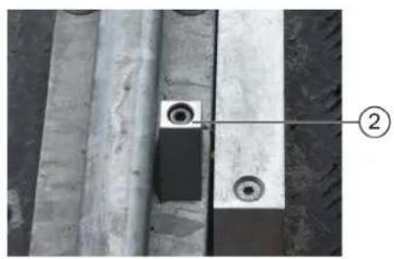
natural_image
Close-up of a concrete beam with two circular holes and a labeled component (②), no readable text or symbols present.
natural_image
Close-up of a metallic industrial control box with a circular dial and four screws, mounted on a wall (no visible text or symbols)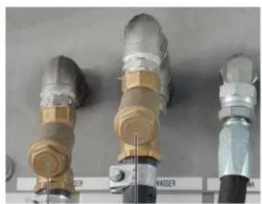
natural_image
Three industrial pipe fittings with brass and metallic components, labeled 'WASSER' (no additional text or symbols visible)④ ③
text_image
Technical diagram of industrial machinery with numbered components and exploded viewstext_image
Technical diagram of a pressure regulator assembly with labeled parts including valve, fittings, and adjustment knobstext_image
Technical diagram showing labeled components of a mechanical device, including parts numbered 1 to 5.text_image
Technical diagram of a vertical pump assembly with labeled components and an inset view showing internal components.Chairman of the Board of Management
S. Reiser
Manager Regulatory Affairs & Certification
71364 Winnenden (Germany)
Tel.: +49 7195 14-0
Fax: +49 7195 14-2212
Winnenden, 01/11/2022
Inhoud
text_image
Technical diagram of an industrial control room with numbered components and close-up insets showing internal wiring and equipment.text_image
Diagram of a car cleaning or dust removal system with numbered components and labeled parts, showing structural components and assembly.text_image
C3 C2 C1 H4 B2 B1 H3 L K G H2 A2 A1 A3A1 = schoon water, chemische drooghulp (CTH), was
A2 = industriewater, shampoo
B1 = industriewater, shampoo
C1 = industriewater, shampoo
C2 = schoon water, CTH, was
C3 = polijsten
text_image
Diagram of an electrical control cabinet with labeled components including switches, a red switch, and warning labels.①Voedingsverdeler
text_image
Electrical control panel with numbered components and labeled switches, wires, and meterstext_image
1 2 3 3 inInstallatie in storing
Toets home
text_image
① ↑ STOP ② ↓ ③natural_image
Five directional arrows arranged in a cross pattern, no text or symbols present
natural_image
3D diagram of a white plastic container with a black cap and threaded screw, labeled with parts 1 and 2 (no text or symbols on the main components)Langdurig stilleggen
text_image
Technical diagram of an industrial control room with numbered components and labeled parts, including a stop unit and electrical equipment.text_image
Diagram of a car cleaning or maintenance system with numbered components and close-ups of cleaning equipment, including brooms, hoses, and sensors.natural_image
Close-up of a metal pipe joint with two bolts and a circular component, no visible text or symbols
natural_image
Close-up of a concrete beam supported by two metal plates with circular holes, no visible text or symbols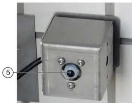
natural_image
Close-up of a metallic industrial sensor or camera unit mounted on a wall, with a numbered label pointing to the component (no visible text or symbols)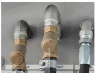
natural_image
Three cylindrical industrial components with metallic and beige fittings, displayed against a plain background (no visible text or symbols)④ ③
text_image
Technical diagram of a mechanical device with numbered parts and exploded views, including a cylindrical component and stacked storage unit.①Hogedrukpomp
②Oliepeilindicator
③Accumulator
④Drukregelaar
⑤Verswaterreservoir
text_image
Technical diagram of a pressure regulator with labeled parts including valve, fittings, and adjustment knobstext_image
Technical diagram showing exploded and assembled views of a mechanical device with numbered components①Verswaterreservoir
②Deksel
③Overloopopening
④Vlotterafsluiter
⑤Uitloop
text_image
Technical diagram of a vertical pump assembly with labeled components and an inset view showing internal structure.①Centrifugaalpomp
H. Jenner
Chairman of the Board of Management
S. Reiser
Manager Regulatory Affairs & Certification
71364 Winnenden (Germany)
Tel.: +49 7195 14-0
Fax: +49 7195 14-2212
Winnenden, 2022/11/01
text_image
Technical diagram of an industrial control room with numbered components and wiring, including a stop unit and internal electronics assembly.text_image
Diagram of a car cleaning or snow-making machine with numbered components and labeled parts, showing structural components and assembly.text_image
C3 C2 C1 H4 B2 B1 H3 L K G H2 A2 A1 A3A1 = agua fresca, agente secador químico (ASQ), cera
A2 = agua tratada, champú
Interruptor principal
text_image
Electrical control panel with numbered components and labeled terminals, including meters and switchestext_image
① ↑ ② STOP ↓ ③natural_image
Diagram showing a red dot with bidirectional arrows pointing up and down, next to a gray car silhouette (no text or symbols)natural_image
3D rendering of a white plastic container with a black cap and threaded screw, labeled with parts 1 and 2 (no text or symbols on the main subject)text_image
Technical diagram of an industrial control room with numbered components and labeled parts, including a stop unit and wiring.text_image
Diagram of a car cleaning or maintenance system with numbered components and close-ups of mechanical components, including spray and wheel assembly.natural_image
Close-up of a metal pipe joint with two circular components, no visible text or symbols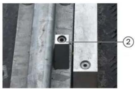
natural_image
Close-up of a concrete beam with two circular holes and a labeled component (②), no readable text or symbols present.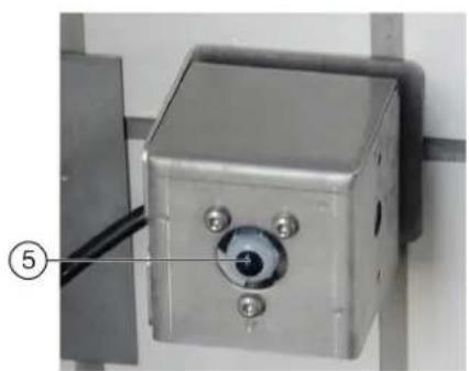
natural_image
Close-up of a metallic industrial control box with a central dial and four screws, mounted on a vertical surface (no visible text or symbols)
natural_image
Three industrial pipe fittings with metallic and brass components, mounted on a wall (no visible text or symbols)④ ③
text_image
Technical diagram of industrial machinery with numbered components and exploded viewstext_image
Technical diagram of a pressure regulator with labeled parts including valve, hose, and adjustment knobstext_image
Technical diagram showing labeled components of a mechanical device with numbered parts 1 to 5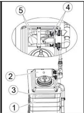
text_image
Technical diagram of a mechanical device with numbered components, likely for assembly or maintenance instructions.text_image
Technical diagram of a vertical pump assembly with labeled components and an inset view showing internal components.2006/42/CE (+2009/127/CE)
2014/30/UE
2009/125/CE + 2009/1781

Chairman of the Board of Management
S. Reiser
Manager Regulatory Affairs & Certification
71364 Winnenden (Germany)
Tel.: +49 7195 14-0
Fax: +49 7195 14-2212
Winnenden, 01/11/2022
Indice
text_image
Technical diagram of an industrial control room with numbered components and close-up insets of equipmenttext_image
Diagram of a car cleaning or snow-making machine with numbered components and labeled parts, showing structural components and assembly.text_image
C3 C2 C1 H4 B2 B1 H3 L K G H2 A2 A1 A3③ Interruptor principal, ver Interruptor principal
Interruptor principal
text_image
Electrical control panel with numbered components and labeled buttons, likely for industrial equipment or measurement setup① Bomba de dosagem
Verificar interruptor final
text_image
① ↑ ② STOP ↓ ③natural_image
3D rendering of a white plastic container with a black cap and threaded screw, labeled with parts 1 and 2 (no text or symbols on the main subject)text_image
Technical diagram of an industrial control room with numbered components and labeled parts, including a stop unit and wiring.text_image
Diagram of a car cleaning or maintenance system with numbered components and close-ups of mechanical components, including brooms, hoses, and sensors.natural_image
Close-up of a metal pipe joint with two circular components, no visible text or symbols
natural_image
Close-up of concrete structural beams and circular components, no visible text or symbols
natural_image
Close-up of a metallic industrial control box with a circular eye and three screws, mounted on a wall (no visible text or symbols)
natural_image
Three industrial pipe fittings with brass and metallic components, no visible text or symbols④ ③
text_image
Technical diagram of industrial machinery with numbered components and exploded viewstext_image
Technical diagram of a pressure regulator assembly with numbered parts for identificationtext_image
Technical diagram showing exploded and assembled views of a mechanical device with numbered componentsVerificar interruptor final
text_image
Technical diagram of a vertical pump assembly with labeled components and an inset view showing internal structure.2006/42/CE (+2009/127/CE)
2014/30/UE
2009/125/CE + 2009/1781
Chairman of the Board of Management

S. Reiser
Manager Regulatory Affairs & Certification
Winnenden, 2022/11/01
Indhold
text_image
Technical diagram of an industrial control room with numbered components and close-up views of internal electronics.text_image
Diagram of a car cleaning or snow-making machine with numbered components and labeled parts, showing structural components and assembly.text_image
C3 C2 C1 H4 B2 B1 H3 L K G H2 A2 A1 A3text_image
Electrical control panel with numbered components and labeled buttons for signal or measurement①Doseringspumpe
②Doseringspumpe shampoo
③Doseringspumpe skum
④Doseringspumpe voks 1
⑤Doseringspumpe forrensning (insekter)
⑥Doseringspumpe voks 2
⑦Doseringspumpe fælgrens (fælgskum)
⑧Doseringspumpe polering
natural_image
3D rendering of a white plastic container with a black cap and threaded screw, labeled with parts 1 and 2 (no text or symbols on the main subject)text_image
Technical diagram of an industrial control room with numbered components and labeled parts, including a stop unit and wiring.text_image
Technical diagram of a car cleaning or maintenance system with numbered components and close-ups of mechanical components.natural_image
Close-up of a metal pipe joint with two circular components, no visible text or symbols
natural_image
Close-up of concrete structural beams and circular components, no visible text or symbols
natural_image
Close-up of a metallic industrial control box with a circular eye and three screws, mounted on a wall (no visible text or symbols)
natural_image
Three industrial pipe fittings with brass and metallic components, no visible text or symbols④ ③
text_image
Technical diagram of industrial machinery with numbered components and exploded viewstext_image
Technical diagram of a pressure regulator with labeled parts including valve, fittings, and adjustment knobstext_image
Technical diagram showing exploded and assembled views of a mechanical device with numbered components①Rentvandstank
text_image
Technical diagram of a pump system with labeled components and an inset view showing internal components.①Centrifugalpumpe
②Udluftningsskrue
2006/42/EF (+2009/127/EF)
2014/30/EU
2009/125/EF + 2009/1781
Chairman of the Board of Management

S. Reiser
Manager Regulatory Affairs & Certification
71364 Winnenden (Germany)
Tlf.: +49 7195 14-0
Fax: +49 7195 14-2212
Winnenden, 2022/11/01
Indhold
Generelle merknader 188
Miljøvern 188
text_image
Technical diagram of an industrial control room with numbered components and close-up insets showing internal wiring and equipment.text_image
Diagram of a car cleaning or snow-making machine with numbered components and labeled parts in Chinesetext_image
C3 C2 C1 H4 B2 B1 H3 L K G H2 A2 A1 A3text_image
Electrical control panel with numbered components and labeled terminals, showing various switches, relays, and wiring connections.Grunnstilling (blå tast)
E5017 31.01.2019 14:24:48

Melding 2/2


text_image
30.64.2018 10:07 d2 Test Plan Service EventorLungen Algorithmize https ① ②text_image
① ↑ ② STOP ↓ ③natural_image
3D rendering of a white plastic container with a black cap and threaded spring, labeled with parts 1 and 2 (no text or symbols on the main subject)①10 liters påfyllingskanne
②Utløpsrør
text_image
Technical diagram of an industrial control room with numbered components and labeled parts, including a stop unit and wiring.text_image
Diagram of a car cleaning or maintenance system with numbered components and close-ups of mechanical components, including brooms, hoses, and sensors.natural_image
Close-up of a metal pipe joint with two circular components, no visible text or symbols
natural_image
Close-up of concrete structural beams and a small circular component with two rings, no visible text or symbols
natural_image
Close-up of a metallic industrial control box with a circular eye and three screws, mounted on a wall (no visible text or symbols)
natural_image
Three industrial pipe fittings with brass and metallic components, no visible text or symbols④ ③
text_image
Technical diagram of industrial machinery with numbered components and exploded viewstext_image
Technical diagram of a pressure regulator with labeled parts including valve, fittings, and adjustment knobs①Deksel
②Pakning
③Sil
④Trykkforminsker
- Ta ut silen og skyll den med vann.
- Sett silen inn i trykkforminskeren. Forsikre deg om at tetningene sitter korrekt.
- Skru på dekselet og stram det.
text_image
Technical diagram showing exploded and assembled views of a mechanical device with numbered componentsendebryter, informer service
F0212 31.01.2019 14:35:29

Melding
2/2


text_image
Technical diagram of a pump system with labeled components and an inset view showing internal components.①Sentrifugalpumpe
②Lufteskrue
2006/42/EF (+2009/127/EF)
2014/30/EU
2009/125/EF + 2009/1781
Anvendte harmoniserte standarder
EN ISO 12100
EN 17281
EN 60204-1
EN 61000-6-2: 2005 + AC: 2005
EN 61000-6-4: 2007 + A1: 2001
Chairman of the Board of Management

S. Reiser
Manager Regulatory Affairs & Certification
71364 Winnenden (Germany)
Tlf.: +49 7195 14-0
Winnenden, 2022/11/01
Innehåll
Allmän information 210
Miljöskydd 210
text_image
Technical diagram of an industrial control room with numbered components and close-up insets showing internal wiring and equipment.text_image
Diagram of a car cleaning or snow-making machine with numbered components and labeled parts in Chinesetext_image
C3 C2 C1 H4 B2 B1 H3 L K G H2 A2 A1 A3text_image
Electrical control panel with numbered components and labeled buttons for signal or measurement①Doseringspump
②Doseringspump schampo
③Doseringspump skum
④Doseringspump vax 1
⑤Doseringspump förrengöring (insekter)
⑥Doseringspump vax 2
⑦Doseringspump fälgrengöring (fälgskum)
⑧Doseringspump polering
text_image
FLOORCHER 3 intext_image
① ↑ ② STOP ↓ ③①Kör framåt
②Stanna, korrekt position
③Kör bakåt
natural_image
Diagram showing a red dot above a gray vehicle silhouette with arrows indicating direction (no text or symbols)natural_image
3D rendering of a white plastic container with a black handle and threaded screw, labeled with parts 1 and 2 (no text or symbols on the main subject)①10 liters påfyllnadstank
②Utloppsrör
text_image
Technical diagram of an industrial control room with numbered components and labeled parts, including a stop unit and wiring.text_image
Diagram of a car cleaning or maintenance system with numbered components and close-ups of mechanical components, including brooms, hoses, and sensors.natural_image
Close-up of a metal pipe joint with two circular components, no visible text or symbols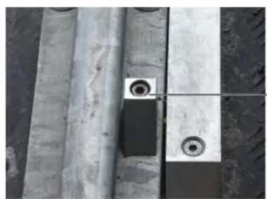
natural_image
Close-up of concrete structural beams and a small circular component with two rings, no visible text or symbols
natural_image
Close-up of a metallic industrial control box with a circular eye and three screws, mounted on a wall (no visible text or symbols)
natural_image
Three industrial pipe fittings with brass and metallic components, no visible text or symbols④ ③
text_image
Technical diagram of industrial machinery with numbered components and exploded views①Högtryckspump
②Indikator oljenivå
③Tryckackumulator
text_image
Technical diagram of a pressure regulator with labeled parts including valve, fittings, and adjustment knobstext_image
Technical diagram showing exploded and assembled views of a mechanical device with numbered components①Färskvattentank
text_image
Technical diagram of a vertical pump assembly with labeled components and an inset view showing internal components.①Kretspump
②Avluftningsskruv
Chairman of the Board of Management
S. Reiser
Manager Regulatory Affairs & Certification
D-71364 Winnenden (Germany)
Tfn: +49 7195 14-0
Fax: +49 7195 14-2212
Winnenden, 01.11.2022
Sisältö
text_image
Technical diagram of an industrial control unit with numbered components and close-up views of internal wiring and equipment.text_image
Diagram of a car cleaning or snow-making machine with numbered components and labeled parts, showing structural components and assembly.text_image
C3 C2 C1 H4 B2 B1 H3 L K G H2 A2 A1 A3text_image
Electrical control panel with numbered components and labeled terminals such as 120kV, 120kΩ, and 25kW.text_image
① ↑ STOP ② ↓ ③natural_image
3D rendering of a white plastic container with a black cap and threaded screw, labeled with parts 1 and 2 (no text or symbols on the main subject)text_image
Technical diagram of an industrial control room with numbered components and labeled parts, including a stop unit and internal electronics.text_image
Diagram of a car cleaning or maintenance system with numbered components and close-ups of mechanical components, including brooms, hoses, and sensors.natural_image
Close-up of a metal pipe joint with two circular components, no visible text or symbols
natural_image
Close-up of concrete structural beams and a small circular component with two rings, no visible text or symbols
natural_image
Close-up of a metallic industrial control box with a circular eye and three screws, mounted on a wall (no visible text or symbols)
natural_image
Three industrial pipe fittings with brass and metallic components, no visible text or symbols④ ③
text_image
Technical diagram of a pressure regulator assembly with labeled parts including valve, fittings, and adjustment knobs.①Kansi
②Tiiviste
③Seula
④Paineenalennin
text_image
Technical diagram showing exploded and assembled views of a mechanical device with numbered componentstext_image
Technical diagram of a pump system with labeled components and an inset view showing internal components.①Keskipakopumppu
② Ilmausruuvi
Chairman of the Board of Management

S. Reiser
Manager Regulatory Affairs & Certification
71364 Winnenden (Germany)
Puh.: +49 7195 14-0
text_image
Technical diagram of an industrial control unit with numbered components and internal wiring, including a stop unit and close-up insets of electrical equipment.①Στήλη 1
text_image
Diagram of a car cleaning or snow-making machine with numbered components and labeled parts, showing structural components and assembly.text_image
C3 C2 C1 H4 B2 B1 H3 L K G H2 A2 A1 A3text_image
Diagram of an electrical control cabinet with labeled components including switches, a red switch, and warning labelstext_image
Electrical control panel with numbered components and labeled terminals, showing wiring and switchestext_image
① ↑ ② STOP ↓ ③natural_image
3D illustration of a white plastic container with a black cap and threaded spring, labeled with parts 1 and 2 (no text or symbols on the main subject)text_image
Technical diagram of an industrial control room with numbered components and labeled parts, including a stop unit and internal wiring.text_image
Technical diagram of a car cleaning or maintenance system with numbered components and close-ups of mechanical components.natural_image
Close-up of a metal pipe joint with two circular components, no visible text or symbols
natural_image
Close-up of concrete structural beams and a small circular component with two rings, no visible text or symbols
natural_image
Close-up of a metallic industrial control box with a circular dial and three screws, mounted on a metal frame (no visible text or symbols)
natural_image
Three industrial pipe fittings with brass and metallic components, no visible text or symbols④ ③
text_image
Technical diagram of industrial machinery with numbered components and exploded viewstext_image
Technical diagram of a pressure regulator assembly with labeled parts including valve, hose, and adjustment knobstext_image
Technical diagram showing exploded and assembled views of a mechanical device with numbered componentstext_image
Technical diagram of a vertical pump assembly with labeled components and an inset view showing internal components.Εγγύηση
Chairman of the Board of Management

S. Reiser
Manager Regulatory Affairs & Certification
71364 Winnenden (Germany)
Tηλ.: +49 7195 14-0
Φαξ: +49 7195 14-2212
Winnenden, 2022/11/01
Содержание
Общие указания 279
text_image
Technical diagram of an industrial control room with numbered components and close-up insets of equipmenttext_image
Diagram of a car cleaning or dust removal system with numbered components and structural detailstext_image
C3 C2 C1 H4 B2 B1 H3 L K G H2 A2 A1 A3text_image
Diagram of an electrical control cabinet with labeled components including switches, buttons, and a warning label.text_image
Electrical control panel with numbered components and labeled buttons, likely for industrial equipment or measurement setuptext_image
① ↑ ② STOP ↓ ③natural_image
Diagram showing bidirectional arrow and vehicle silhouette (no text or symbols)natural_image
3D rendering of a white plastic container with a black cap and threaded spring, labeled with parts 1 and 2 (no text or symbols on the main subject)text_image
Technical diagram of an industrial control room with numbered components and labeled parts, including a stop unit and wiring.text_image
Diagram of a car cleaning or maintenance system with numbered components and close-ups of cleaning equipment, including brooms, hoses, and sensors.natural_image
Close-up of a metal pipe joint with two circular components, no visible text or symbols
natural_image
Close-up of concrete structural beams and a small circular component with two rings, no visible text or symbols
natural_image
Close-up of a metallic industrial control box with a circular dial and three screws, mounted on a metal frame (no visible text or symbols)
natural_image
Three industrial pipe fittings with brass and metallic components, no visible text or symbols④ ③
text_image
Technical diagram of a mechanical device with numbered parts and exploded views, including a cylindrical component and stacked storage unit.text_image
Technical diagram of a pressure regulator assembly with labeled parts including valve, hose, and adjustment knobstext_image
Technical diagram showing labeled components of a mechanical device with numbered parts 1 to 5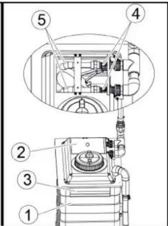
text_image
Technical diagram of a mechanical device with numbered components, likely for assembly or maintenance instructions.text_image
Technical diagram of a vertical pump assembly with labeled components and an inset view showing internal components.Chairman of the Board of Management
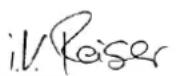
S. Reiser
Manager Regulatory Affairs & Certification
71364 Winnenden (Germany)
Тел.: +49 7195 14-0
Факс: +49 7195 14-2212
text_image
Technical diagram of an industrial control room with numbered components and close-up insets showing internal wiring and equipment.text_image
Diagram of a car cleaning or snow-making machine with numbered components and labeled parts, showing structural components and assembly.text_image
C3 C2 C1 H4 B2 B1 H3 L K G H2 A2 A1 A3text_image
Diagram of an electrical control cabinet with labeled components including switches, a red switch, and warning labels①Elosztó
text_image
Electrical control panel with numbered components and labeled buttons, likely for industrial monitoring or wiring setuptext_image
FLOCHER 3 l/htext_image
① ② STOP ③natural_image
Diagram showing bidirectional arrows and a vehicle silhouette with four wheels (no text or symbols)natural_image
3D rendering of a white plastic container with a black cap and threaded spring, labeled with parts 1 and 2 (no text or symbols on the main subject)text_image
Technical diagram of an industrial control room with numbered components and labeled parts, including a stop unit and electrical equipment.text_image
Diagram of a car cleaning or maintenance system with numbered components and close-ups of mechanical components, including brooms, hoses, and sensors.text_image
Technical diagram of a mechanical device with numbered parts and exploded views, including a cylindrical component and stacked storage unit.text_image
Technical diagram of a pressure regulator assembly with numbered parts for identificationtext_image
Technical diagram showing exploded and assembled views of a mechanical device with numbered componentstext_image
Technical diagram of a pump system with labeled components and an inset view showing internal components.Chairman of the Board of Management
S. Reiser
Manager Regulatory Affairs & Certification
Winnenden, 2022/11/01

natural_image
Black silhouette of a hand giving a thumbs-up gesture (no text or symbols)THANK YOU!
MERCI! DANKE! iGRACIAS!

Register your product and benefit from many advantages.
www.kaercher.com/welcome


Rate your product and tell us your opinion.
natural_image
Icon showing a gear and wrench inside a square frame (no text or symbols)www.kaercher.com/dealersearch
Alfred Kärcher SE & Co. KG
Alfred-Kärcher-Str. 28-40
71364 Winnenden (Germany)
Tel.: +49 7195 14-0
Fax: +49 7195 14-2212