WS 1700 - Weather Station TECHNOLINE - Free user manual and instructions
Find the device manual for free WS 1700 TECHNOLINE in PDF.
| Product type | Weather station with wireless outdoor sensors |
| Brand | TECHNOLINE |
| Model | WS 1700 |
| Main unit power supply | 3 AAA 1.5 V batteries or DC 5.0 V power adapter |
| Outdoor sensors power supply | 2 AA 1.5 V batteries |
| Transmission frequency | 433 MHz |
| Maximum range | Up to 100 m in open field |
| Indoor temperature range | -9.9 °C to +50 °C |
| Outdoor temperature range | -20 °C to +70 °C |
| Humidity range | 20 % to 95 % |
| Atmospheric pressure range | 850 hPa to 1050 hPa |
| Precipitation range | 0 to 999.99 mm |
| Wind speed range | 0 to 256 km/h |
| Wind direction | 16 directions |
| Time display | DCF77 radio-controlled, 12/24 h format, calendar |
| Alarms | Dual alarm with snooze function (5 min) |
| Weather forecast | Sunny, slightly sunny, cloudy, rainy, heavy rain |
| Moon phases | 8 phases displayed |
| Maintenance and cleaning | Clean with a slightly damp cloth; do not use solvents; do not immerse |
| Safety | Do not open the housing; use only non-rechargeable alkaline batteries; keep out of reach of children |
| General information | Compliant with directive 2014/53/EU and ROHS 2011/65/EC |
Frequently Asked Questions - WS 1700 TECHNOLINE
User questions about WS 1700 TECHNOLINE
0 question about this device. Answer the ones you know or ask your own.
Ask a new question about this device
Download the instructions for your Weather Station in PDF format for free! Find your manual WS 1700 - TECHNOLINE and take your electronic device back in hand. On this page are published all the documents necessary for the use of your device. WS 1700 by TECHNOLINE.
USER MANUAL WS 1700 TECHNOLINE
natural_image
Diagram of a device with two connectors and internal components, showing wiring connections (no text or symbols)HINWEIS
natural_image
Pure mechanical diagram showing a lever system with pulleys and weights, no text or symbols presentnatural_image
Pure mechanical diagram showing a lever mechanism with no text, numbers, or symbolsnatural_image
Technical line drawing of a mechanical assembly with spring-loaded components and a shaft (no text or symbols)Das "Alarm up / down"

Thank you for purchasing this Weather Station, Please read the operating instructions carefully to familiarize yourself with the features and modes of operation before using the instrument.
Keep the manual for future reference and pass it on with the device, if you pass on the device to other users.
NOTE: Always remember to use high quality batteries & change them at least once per year.
Package Contents
Carefully unpack and remove the contents:
• 1x Weather station main unit
- 1x Stainless steel mast
• 1x Thermo-hygro sensor
- 1x Rain sensor
- 1x Wind speed sensor
- 1x Wind direction sensor
- 1x Radiation shield
- Mounting screws
- Stainless steel accessory for fixing the mast.
Product overview
other
| Time | Value | | :--- | :--- | | 00:00 | 23.5 | | 01:00 | 23.7 | | 02:00 | 23.9 | | 03:00 | 24.1 | | 04:00 | 24.3 | | 05:00 | 24.5 | | 06:00 | 24.7 | | 07:00 | 24.9 | | 08:00 | 25.1 | | 09:00 | 25.3 | | 10:00 | 25.5 | | 11:00 | 25.7 | | 12:00 | 25.9 | | 13:00 | 26.1 | | 14:00 | 26.3 | | 15:00 | 26.5 | | 16:00 | 26.7 | | 17:00 | 26.9 | | 18:00 | 27.1 | | 19:00 | 27.3 | | 20:00 | 27.5 | | 21:00 | 27.7 | | 22:00 | 27.9 | | 23:00 | 28.1 | | 24:00 | 28.3 | | 25:00 | 28.5 | | 26:00 | 28.7 | | 27:00 | 28.9 | | 28:00 | 29.1 | | 29:00 | 29.3 | | 30:00 | 29.5 | | 31:00 | 29.7 | | 32:00 | 29.9 | | 33:00 | 30.1 | | 34:00 | 30.3 | | 35:00 | 30.5 | | 36:00 | 30.7 |
text_image
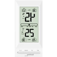
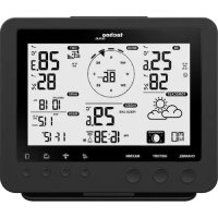
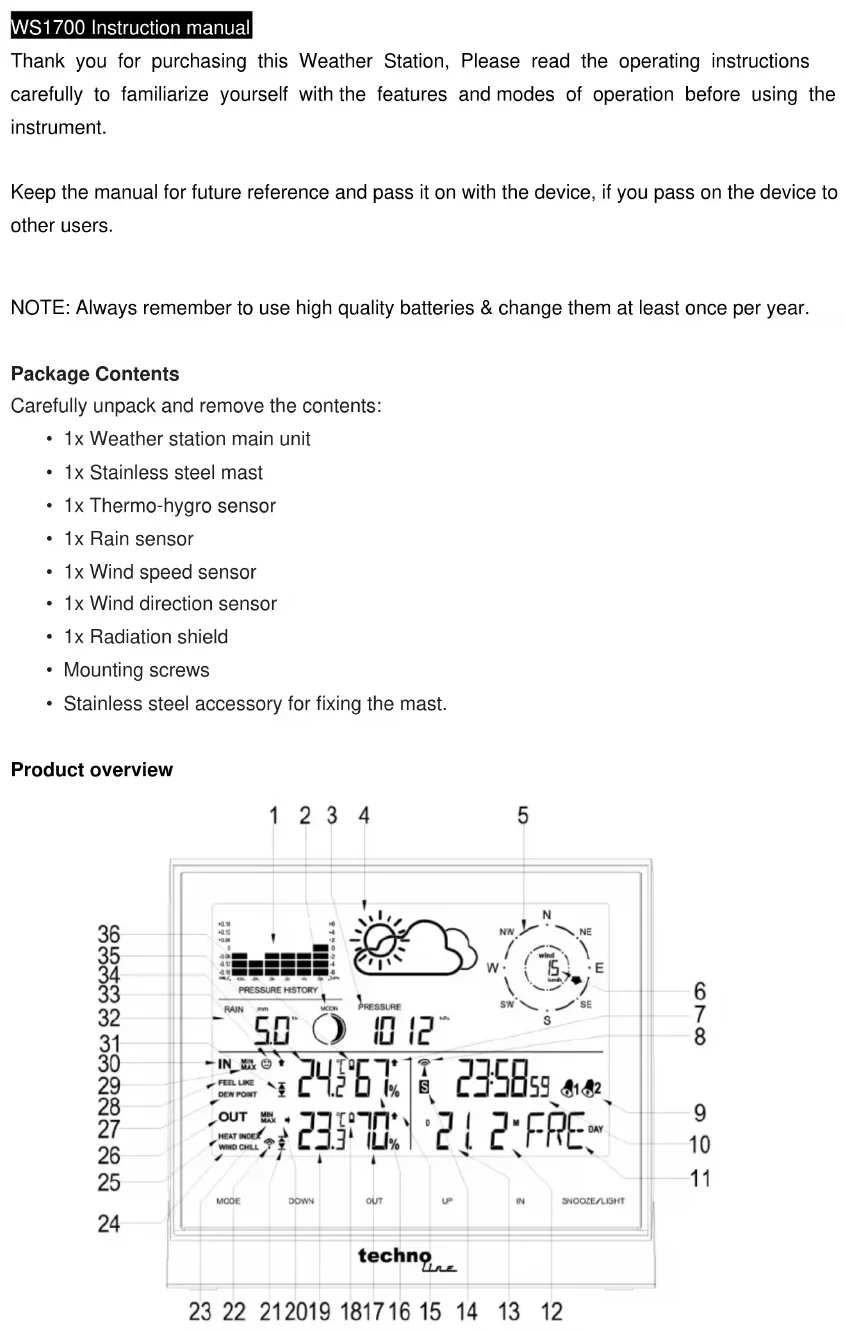
PRESSURE HISTORY RAIN mm MODE pressure 5.0 10 12 °F IN MIN MAX 24.2°67° S 23:58.59 12 FEEL LIKE DEW POINT OUT MIN MAX 23.3°70° D 21.2°FRE DAY HEAT INDEX WIND CHILL MODE DOWN OUT UP IN SNOOZE/LIGHT techno A B C D E F
text_image
G H I1 12 hour air pressure history bar
2 Moon phase
3 Air pressure
4 Weather forecast
5 Wind direction
6 Wind speed
7 Indoor humidity trend
8 Radio Controlled Clock indicator
9 Alarm
10 Time
11 Day of week
12 Month (in DM mode) / Date (in MD mode)
13 Date (in DM mode) / Month (in MD mode)
14 Daylight Saving Time
15 Outdoor humidity trend
16 Indoor humidity
| 17 Outdoor humidity | 29 Indoor MAX / MIN |
| 18 Outdoor low battery indicator | 30 Indoor information |
| 19 Outdoor temperature | 31 Indoor temperature alert |
| 20 Outdoor temperature trend | 32 Rainfall |
| 21 Outdoor temperature alert | 33 Living space icon |
| 22 RF outdoor sensor reception indicator | 34 Indoor temperature trend |
| 23 Outdoor MAX / MIN | 35 Indoor temperature |
| 24 Wind Chill | 36 Indoor low battery indicator |
| 25 Heat Index | |
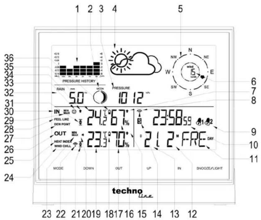
| 26 Outdoor sensor information | G Power adaptor socket |
| 27 Dew point | H Battery compartment |
| 28 Feel like | I Stand |
| Press button | Hold button | |
| (A) MODE | Time / Alarm1 / Alarm2 / In temp alert / Out temp alert mode switching | Setting the time, setting the alarm time, setting the temperature alert |
| (B) DOWN | 1. One step back in setting2. View the rainfall 1hr / 24hr / TOTAL3. Alarm on / off in alarm mode | Clear the rainfall reading |
| (C) OUT | View heat index and wind chill | Search for Radio Frequency outdoor sensor |
| (D) UP | 1. One step forward in setting2. View the Max / Min temperature and humidity3. Alarm on / off in alarm mode | Clear the Max / Min temperature and humidity record |
| (E) IN | View feel like / dew point | Start or end RCC reception |
| (F) SNOOZE/ LIGHT | 1. Activates alarm snooze2. Display back light (when without power adaptor plugged in)3. Change display brightness (when power adaptor plugged in) | Altitude and weather icon setting |
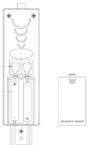
Getting Started with Power Supply
Insert batteries:
- Gently remove the stand downwards and remove battery compartment cover from the main unit.
- Insert 2 x AA Mignon batteries, matching the polarities (+/-).
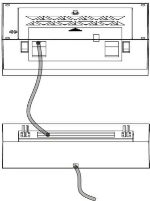
DC Power:
- Put the power cable pass through the hole in the stand, plug the power cable to the power jack and plug the power adapter into a suitable power outlet.
natural_image
Diagram of a device showing two connected components with connectors and wiring (no text or symbols)NOTE
It is recommended to insert the battery as backup for regular dc power.
Outdoor sensor
- Pull away the radiation shield off the thermo-hygro sensor to reveal the 2 sockets for the wind sensor and rain sensor.
-
Open the thermo-hygro sensor battery door, insert 2 x AA Mignon batteries, matching the polarities (+/-).
Note: To prevent water from entering the sensor, it is important to make sure the battery lid closes tightly. -
Place the sensor near the main unit in order to establish an effective wireless transmission. Do not place the sensor outside until the transmission has been confirmed.
- Observe the LCD screen to see outdoor temperature and humidity displayed to confirm the transmission is completed
NOTES:
- First plug in the adaptor or insert the batteries of main unit, then insert the batteries of the outdoor sensor in 3 minutes after the main unit is powered on, to assure of the sensor data received well.
In case of the outdoor sensor data received failure, please press "OUT" key for more than 3 seconds to synchronize the transmission signal. - Every time the power adaptor gets unplugged and with no batteries inserted, the main unit will lose all the weather data.
- Every time the outdoor sensor batteries are replaced, the sensor will synchronize with the main unit again. You must press the "OUT" key for more than 3 seconds to synchronize the reception signal.
Mounting the main unit
The main unit can be placed onto any flat surface or wall mounted at the desired location by hanging hole, It is important to check that the radio signal (from the outdoor sensor and from the DCF77 time signal) can be received well before mounting.
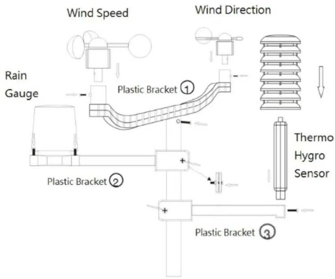
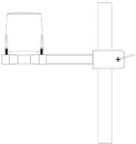
1) Mounting the outdoor sensor onto the stainless steel mast
For accurate results, the outdoor sensor mast should be securely mounted onto a horizontal surface and in an open area away from trees and other coverings where rainfall or wind speed may be reduced causing inaccurate reading.
The following diagram shows how the parts go together.
flowchart
graph TD
    A["Wind Speed"] --> B["Rain Gauge"]
    B --> C["Plastic Bracket ①"]
    C --> D["Plastic Bracket ②"]
    D --> E["Plastic Bracket ③"]
    E --> F["Thermo Hygro Sensor"]
    G["Wind Direction"] --> H["Top Wind Turbine"]
    H --> I["Downward Flow"]
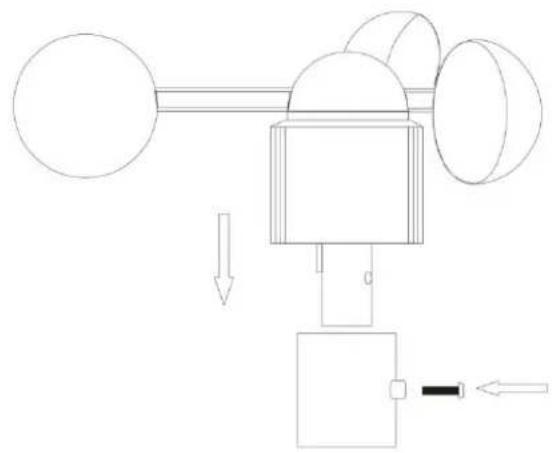
2) Mounting the wind speed sensor to the ① plastic bracket: first check the wind-fan can rotate freely before fixing. The wind speed sensor should now be mounted onto the bracket provided to allow the wind to travel around the sensor unhindered from all directions. Then fix it with bolt and screw. Please follow the below display:
natural_image
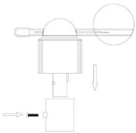
Pure mechanical diagram showing a lever system with pulleys and weights, no text or symbols present3) Mounting the wind direction sensor to the bracket: first check the wind direction
sensor before fixing, the wind direction sensor should now be mounted onto the bracket provided to allow the wind to travel around the sensor unhindered from all directions. Then fix it with bolt and screw. There is one cable from wind speed sensor, please insert it into the socket under the wind direction sensor. Please follow the below display:
natural_image
Pure mechanical diagram showing a lever mechanism with no text, numbers, or symbolsAttention!! Please align the "North" indicator sticker with the NORTH direction to enable it to record accurate reading
4) Mounting the rain sensor to the ② bracket: there are vertical engraved lines at the bottom edge of the round cover and the sensor part, you only need adjust the two line into one position, then turn clockwise, the rain sensor part will be connected well, then fix them with 4 screws and bolt onto the plastic bracket. Please follow the below display:
natural_image
Pure technical line drawing of a mechanical assembly without any text, numbers, or symbols- Note: The cover of the Rain Gauge can be removed by rotating in an anti-clockwise direction. When replacing the cover it will only fit in one position. When you find the correct position it fits snugly on, and then rotate it clockwise to secure the cover in place.
- It is important that the cover is securely located.
5) Mounting the thermo-hygro sensor to the bracket:
Once the wind sensors and rain sensor are fixed onto the bracket, insert the cables from the Wind Sensor & the Rain Gauge into the correct sockets. These are label on the plastic under the sockets.
text_image
WIND RF REMOTE SENSORSo that data can be transmitted to the main unit, then put the radiation shield onto the thermo-hygro sensor, please follow the below display:
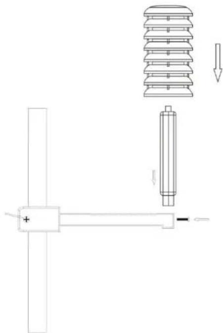
natural_image
Technical line drawing of a mechanical assembly with no visible text or symbolsNote: please don't put in or take off the plug very often, or put the plug outside in the air so long time to avoid any damage of the plug, as this can result in bad connection.
6) Mounting all the sensors onto the stainless steel mast and fix the whole parts at outdoor open area (please refer to the illustration above)
Note: please make sure all the cables are connected well into the sockets)
Attention!! Ensure that the outdoor sensor can be received from the base station at its intended location before the final installation of the outdoor sensor takes place at its final location.
Initial Operation
- After inserting the batteries, the altitude flashing in meters, press "UP" or "DOWN" to set the altitude of your position, then press "SNOOZE/LIGHT" to confirm
- The weather icon flashing, press "UP" or "DOWN" to choose the weather, then press "SNOOZE/LIGHT" to confirm
-
The main unit will connect with the outdoor sensor by RF signal. The RF signal symbol at the out area will flash.
-
This process takes about 3 minutes. Then the display shows the outdoor temperature /humidity/wind speed/wind direction/rainfall, in case of failure of reception, please press "OUT" for more than 3 seconds to receive again.
- The automatic receiving of the DCF77 radio signal begins after 3 minutes of outdoor RF reception.
- This RCC reception process is going on, the flashing symbol "radio tower" appears in the time display area at the same time.
- Once radio signal receiving is successful, the display shows the symbol "radio tower" continuously
Reception of radio controlled signal
- DCF77 radio signal search starts automatically about 3 minutes after battery exchange. The “radio tower” signal is flashing.
- Press "IN" for more than 3 seconds to enter or quit the Radio controlled signal reception
- Flashing "radio tower" symbol stands for DCF77 radio signal reception started.
- Continuous "radio tower" symbol stands for DCF77 radio signal reception successful.
- If the synchronization is unsuccessful, the "radio tower" symbol disappears.
- The clock synchronizes with the DCF77 radio signal automatically and daily from 1:00AM to 3:00AM to correct potential time deviations each hour. If the reception is unsuccessful, a further synchronization attempt is made at 4:00AM and 5:00AM until success. If it is still not success at 5:00AM, the daily reception will stop.
Information
- Please observe a minimal distance of 2.5m to sources of interference such as televisions or computer screens.
- The radio signal is weaker in rooms with concrete walls (e.g. in the basement) and in office buildings. For extreme cases, please put the main unit near a window.
- There are less atmospheric disturbances at night. A radio time signal reception is usually possible at that time. One synchronization per day is sufficient to keep the time display accuracy at 1 second.
Hint
You can adjust the time manually in case the clock cannot receive the DCF radio signal (due to interference, large distance to the sender, obstructions like mountains, etc.) As soon as the radio signal can be received, the clock will be adjusted automatically.
Manual setting
- Press "MODE" to switch to the "Time display mode"
- Press and hold the "MODE" button for 3 seconds.
- The 12/24 hour flashing. Use "UP" and "DOWN" to select.
- Press "MODE" to confirm.
- The display for the time zone is flashing. Use "UP" and "DOWN" to select the time zone (-12 to +12).
- Press "MODE" to confirm.
• The DM/MD flashing, Use "UP" and "DOWN" to select. - Press "MODE" to confirm.
- The display for the year is flashing. Use "UP" and "DOWN" to select the year.
- Press "MODE" to confirm.
- The display for the month is flashing. Use“UP” and “DOWN” to select the month.
- Press "MODE" to confirm.
- The display for the date is flashing. Use "UP" and "DOWN" to select the date.
- Press "MODE" to confirm.
- The display for the hour is flashing. Use "UP" and "DOWN" to select the hour.
- Press "MODE" to confirm.
- The display for the minutes is flashing. Use "UP" and "DOWN" to select the minutes.
- Press "MODE" to confirm.
- The language selection for the display of the weekdays is flashing. Use "UP" and "DOWN" to select the language (GER-German, ENG-English, ITA-Italian, FRE-French, DUT-Dutch, SPA-Spanish, DAN-Danish).
- Press "MODE" to confirm
- The °C/°F for temperature flashing, Use "UP" and "DOWN" to select the temperature unit.
- Press "MODE" to confirm.
- The hPa/inHg for air pressure flashing, Use "UP" and "DOWN" to select.
- Press “MODE” to confirm.
- The mm/inch for rainfall and km/hmph flashing, Use "UP" and "DOWN" to select.
- Press "MODE" to confirm and exit setting mode.
Information:
- The station automatically exits the set-up mode if no keys are pressed for 20 seconds.
- Explanation for the time zone display:
- The station automatically exits the set-up mode if no keys are pressed for 20 seconds. - Explanation for the time zone display:
You can manually adjust the clock to the time zone of a country (up to 1500km distance to Frankfurt/Main) where the clock receives the DCF77 signal but where the actual time differs from the time received.
If, e.g. the time in a given country is 1 hour ahead of the German time, set the time zone display to 01. The clock is now DCF77 controlled but the time is one hour ahead.
Daily alarm set-up
- Press "MODE" to switch to "Alarm1" mode, "A1" and the alarm displayed
- Press and hold the key "MODE" for 3 seconds, the flashing alarm time are shown
- The hour display of the alarm time is flashing. Use "UP" and "DOWN" to select the hour. Press "MODE" to confirm.
- Then follow the minutes. Use "UP" and "DOWN" to select the minutes,
- Press "MODE" to confirm.
- Then press "MODE" to switch to "Alarm2" mode, "A2" and the alarm displayed
- Press and hold the key "MODE" for 3 seconds, the flashing alarm time are shown
- The hour display of the alarm time is flashing. Use "UP" and "DOWN" to select the hour. Press "MODE" to confirm.
- Then follow the minutes. Use "UP" and "DOWN" to select the minutes,
- Press "MODE" to confirm.
Daily alarm on/off
- Press "MODE" to switch from time display to "Alarm 1" or "Alarm 2" mode
- When showing A1 or A2 alarm time, press "UP" or "DOWN" to activate the alarm with alarm symbol showing.
- Press "UP" or "DOWN" again to cancel the alarm
- The clock automatically changes from set-up mode to time mode if no keys are pressed for 20 seconds.
- The alarm sounds for 2 minutes if no key is pressed to stop it.
Information:
Snooze function
To activate the snooze function, follow the steps below
- Press the key "SNOOZE/LIGHT", while the alarm sounds, to activate the snooze function.
• If the snooze function is activated, alarm symbol is flashing.
• The alarm repeat after 5 minutes. - The snooze function can be stopped by pressing any other key than "SNOOZE/LIGHT"
Temperature alert set-up
- Press "MODE" to switch to "Temperature alert" mode
- In the "Temperature alert" mode, the indoor / outdoor temperature alert upper limit and the
icon displayed.

- Press "MODE" again the indoor / outdoor temperature alert lower limit and icon displayed.
- In the "Temperature alert" mode, press and hold the "MODE" key, until the "alert up /
down" icon


icon
- Press "UP" or "DOWN" to set the alert on or off. The "alert up / down" icon showed when it turned on.
- Press "MODE" to confirm
- The indoor upper limit temperature alert and the upper alert icon are flashing, press "UP" or "DOWN" to set the maximum alert temperature.
- Press "MODE" to confirm
- The indoor lower limit temperature alert and the lower alert icon are flashing, press "UP" or "DOWN" to set the minimum alert temperature.
- Press "MODE" to confirm
- The outdoor upper limit temperature alert and the upper alert icon are flashing, press "UP" or "DOWN" to set the maximum alert temperature.
- Press "MODE" to confirm
- The outdoor lower limit temperature alert and the lower alert icon are flashing, press "UP" or "DOWN" to set the minimum alert temperature.
- Press "MODE" to confirm, the weather station will return to the "Time display mode"
Information
- The clock automatically changes from temperature alert mode to time mode if no keys are pressed for 20 seconds.
- The lower alert temperature selected must at least be 1^ C below the upper alert selected temperature.
Temperature alert ring:
- When the temperature reach the set alert level and when alert turned on, the alert symbol

flash with alert sound
- Press any key to stop the alert sound, the alert symbol and corresponding temperature still flash until the temperature is out of alert range
- Or Press “MODE” to switch to the “Temperature alert mode”, press and hold the “MODE” key to enter setup, then press “UP” or “DOWN” to deactivate the alert
12/24 hours mode
- The time display can be in 12 (AM/PM) or 24 hours mode, please follow the "Manual set-up" section to select
°C/°F temperature display
- The temperature display can be in °C or °F, please follow the "Manual set-up" section to select.
Max. / Min. for the indoor/outdoor temperature and humidity
- Press "MODE" to switch to "Time display" / "Indoor temperature alert" / "Outdoor temperature alert" mode
- Press "UP" to display indoor and outdoor max temperature and humidity,
- Press "UP" again to display indoor and outdoor min temperature and humidity
- Hold "UP" for more than 3 seconds to clear up the max./min.
Wind speed in mph/kmh (0\~256kmh)
- The wind speed can be shown in mph and kmh, please follow the "Manual set-up" section to select mph/kmh, the display of the speed is updated in case of the sensor updated every 1 minute.
Wind direction
- There will be 16 wind directions, the display of the direction is updated in case of the sensor updated every 1 minutes
Rainfall display (0\~999.99mm)
- Rain fall can be shown in mm and inch, please follow the "Manual set-up" section to select the mm/inch.
- Press "MODE" to switch to "Time display" mode.
- Press "DOWN" to switch to 1Hour, press again to 24 Hour, then Total wind speed and rainfall
- Press and hold "DOWN" to clear up the volume accordingly, such as if showing 1 hour, clear up the data in 1 hour, others unchanged, if showing 24 hours, clear up the data in 24 hour, others unchanged.
- The max. of the rainfall is up to 999.99mm (99.99inch), the display is flashing in case of the max., you have to clear up the data by hand, otherwise, the data can not be updated any more.
Weather forecast
 |  |  |  |  |
| Sunny | Slightly Sunny | Cloudy | Rainy | Heavy Rain |
Remarks:
- As the weather forecast is calculated by air pressure only, the display will have discrepancy with the actual weather.
- Currently displayed icon means the forecast for the next 12–24 hours. It may not reflect the current state of the weather.
Altitude setting and barometer
- After inserting batteries or plugged in adaptor into the weather station, or by pressing and holding the "SNOOZE/LIHGT" button, set your altitude for more precise pressure calculation.
- Use the "UP" and "DOWN" buttons to set a value in the range -190 m to 2000 m (10 m increment). , press "SNOOZE/LIHGT" to confirm.
- After setting the altitude, use "UP" and "DOWN" buttons to set the weather forecast icon, press "SNOOZE/LIHGT" to confirm
- For accurate barometric pressure trends, the weather station should operate at the same altitude for recordings (i.e. it should not be moved from the ground to the second floor of the house). When the unit is moved to a new location, discard readings for the next 12 hours and correct the height adjustment (see "Initial operation") if needed.
Temperature, humidity and pressure trends
- The arrow shows the trends of values of the temperature and humidity measurements on sensor or station.
| Indications on the display |  |  |  |
| Temperature and humidity trends | Rising | Constant | Falling |
Moon phase display
Icons for the main phases of the moon are as follows:
 |  |  |  |  |  |  |  |
| New moon | Waxing crescent | First quarter | Waxing gibbous | Full moon | Waning gibbous | Last quarter | Waning crescent |
Living space icon
The weather station uses saved data to determine the indoor humidity in the living space to show the respective symbols for your health and home environment.
| Comfortable | (HYK) |
| Dry | (22×10) |
| Wet | (CTT) |
- If the indoor humidity is within 40–70 % RH and the temperature within 20–28 °C, the 😊 icon (comfortable environment) will be displayed.
- If the indoor humidity is lower than 40 % RH, the icon (dry environment) will be displayed.
- If the indoor humidity is higher than 70 % RH, the icon (wet environment) will be displayed.
- If the temperature is not within 20–28 °C and humidity is within 40–70% RH, no icon will be displayed.
Feel Like and Dew Point
Press "IN" to display "Feel Like", press "IN" again to display "Dew Point"
- "Feel Like" temperature is a measurement of how hot or cold you really feel like. It is measured by the temperature, humidity, and wind speed.
- “Dew point” is the temperature to which air must be cooled to become saturated with water vapor.
- When the dew point value is below 0^ , "LL.L" display
- When the dew point value is above 60°C, "HH.H" display
Heat Index and Wind Chill
Press "Out" to display "Heat Index", press "Out" again to display "Wind Chill"
- “Heat Index” combines the factors of heat and humidity. It is the apparent temperature of how hot it feels to a human being.
- Note: Heat Index is only displayed when temperature above 26.7°C
- "Wind Chill" is a measure of how cold felt by the body on exposed skin due to the flow of air.
- Note: Wind Chill is only displayed when temperature below 5^ C and wind speed above 3kmh
Backlight
- When plugged in power adaptor, press "Snooze/Light" to dim the backlight brightness or turn the display off
- When powered by batteries only, the backlight will be automatically off after 10 seconds without pressing any keys, press “Snooze/Light” to activate it for 10 seconds.
Low battery condition display
The weather station displays the low battery condition symbol to remind the batteries of the weather station or the outdoor sensor need to be exchanged.
- Weather station low battery condition display: within indoor area of the display
- Outdoor sensor low battery condition display: in the outdoor area of the display
Troubleshooting
| Display screen not working | Check the batteries in main unit are inserted and power adaptor is plugged in correctly |
| No outdoor sensor reception | Check the batteries in sensor are inserted correctlyBattery may need to be replacedRelocate the weather station and the sensor. The maximum transmission range is 100m without obstructionPress and hold “OUT” key for RF reception againTry to reset the units, take the sensor near the weather station, reinstall the batteries and replug power adaptor, place the sensor outdoor until reception successCheck the distance of the weather station and the sensor from the sources of interference (computer monitors or television sets). It should be at least 1.5 to 2 m during the reception of the signal. |
| Rainfall display error | Remove rain gauge cover to see if any obstruction insideMake sure the rain gauge is mounted securelyMake sure the outdoor sensor cable connect properly |
| Inaccurate weather forecast | Currently displayed icon means the forecast for the next 12–24 hours. It may not reflect the current state of the weather.Set the correct altitudeFor accurate barometric pressure trends, the weather station should operate at the same altitude for recordings (i.e. it should not be moved from the ground to the second floor of the house). When the unit is moved to a new location, discard readings for the next 12 hours and correct the height adjustment if needed |
| No RCC signal | Move the weather station to another location and try to detect the DCF signal again.Check the distance of the weather station from the sources of interference (computer monitors or television sets). It should be at least 1.5 to 2 m during the reception of the signal.When receiving DCF77 signal, do not put the weather station to the proximity of metal doors, window frames and other metal structures or objects (washing machines, dryers, refrigerators etc.).In reinforced concrete structures (cellars, high-rise buildings etc.), the DCF signal reception is weaker, depending on the conditions. In extreme cases, place the weather station close to a window |
| Wrong temperature | Press “MODE” to check if it is in alert mode. In the alertmode, the unit will display the alert upper or lower limit. |
Care and maintenance
- Read carefully the manual before using this product.
- Do not expose the main unit to direct sunlight, extreme cold and moisture, and sudden changes in temperature. This would reduce the accuracy of detection.
- Do not place the product in locations prone to vibration and shocks – these may cause damage.
- Do not expose the product to excessive force, impacts, dust, high temperatures or humidity - these may cause malfunction, shorter battery life, damage to batteries and deformation of plastic parts.
- Do not expose the main unit to rain or moisture, if it is not intended for outdoor use.
- Do not place any open flame sources on the product, e.g. a lit candle, etc.
- Do not place the product to places with inadequate air flow.
- Do not insert any objects in the product vents.
- Do not tamper with the internal electric circuits of the product – you may damage it, which will automatically terminate the guarantee. The product should only be repaired by a qualified professional.
- To clean the product, use a slightly moistened soft cloth. Do not use solvents or cleaning agents - they could scratch plastic parts and damage electric circuits.
- Do not immerse the product in water or other liquids.
● The main unit may not be exposed to dripping or splashing water.
- In the event of damage or defect of the product, do not perform any repairs by yourself.
- The transmitter of the wireless indoor/outdoor thermometer works down to -20^ , but at low temperatures, especially for a long period of time, the batteries may freeze, which may prevent the transmitter from transmitting the signal to the receiver and at the same time the transmission range is reduced at very low temperatures.
- This device is not intended for use by persons (including children) whose physical, sensory or mental disability or lack of experience and expertise prevents safe use, unless they are supervised or instructed regarding use of the appliance by a person responsible for their safety. It is necessary to supervise children to ensure they do not play with the device.
Note
● Manufacturer reserves the right to change specifications of the product.
● Manufacturer and supplier are not responsible for malfunction where interference occurs.
● This product is not intended for medical or commercial purposes.
Environmental reception effects
The station obtains the accurate time with wireless technology. Same as all wireless devices, the reception is maybe affected by the following circumstances:
- long transmitting distance
- nearby mountains and valleys
- near freeway, railway, airports, high voltage cable etc.
- near construction site
- among tall buildings
• inside concrete buildings
• inside moving vehicles
- near electrical appliances (computers, TV's, etc) and metallic structures
Place the station at a location with optimal signal, i.e. close to a window and away from metal surfaces or electrical appliances.
Precautions
- This main unit is intended to be used only indoors. Only the transmitter should be used outdoors.
- Do not subject the unit to excessive force or shock.
- Do not expose the unit to extreme temperatures, direct sunlight, dust or humidity.
- Do not immerse in water.
- Avoid contact with any corrosive materials.
- Do not dispose this unit in a fire as it may explode.
- Do not open the inner back case or tamper with any components of this unit.
Batteries safety warnings
- Use only alkaline batteries, not rechargeable batteries.
• Install batteries correctly by matching the polarities (+/-). - Always replace a complete set of batteries.
- Never mix used and new batteries.
- Remove exhausted batteries immediately.
- Remove batteries when not in use.
- Do not recharge and do not dispose of batteries in fire as the batteries may explode.
- Ensure batteries are stored away from metal objects as contact may cause a short circuit.
- Avoid exposing batteries to extreme temperature or humidity or direct sunlight.
- Keep all batteries out of reach from children. They are a choking hazard.
Use the product only for its intended purpose!
Consideration of duty according to the battery law

Old batteries do not belong to domestic waste because they could cause damages of health and environment. You can return used batteries free of charge to your dealer and collection points. As end-user you are committed by law to bring back needed batteries
to distributors and other collecting points!
Consideration of duty according to the law of electrical devices
This symbol means that you must dispose of electrical devices separated from the General household waste when it reaches the end of its useful life. Take your unit to your local waste collection point or recycling centre. This applies to all countries of the European Union, and to other European countries with a separate waste collection system.
Hereby, Technotrade declares that this product WS1700 is in compliance with the essential requirements and other relevant provisions of Directive 2014/53/EU and ROHS 2011/65/EC.
The original EU declaration of conformity may be found at:
● Barometer unit: hPa / inHg
● Barometer pressure measuring range: 850hPa to 1050hPa
● Weather display: Sunny, Slightly Sunny, Cloudy, Rainy, Storm
● Temperature unit: °C / °F
● Temperature measurement range: -9.9 °C to +50 °C
- Indoor temperature / humidity trend and max / min function
- Moon phase
● Humidity measurement range: 20 to 95%
● Living space humidity display
● Time display: 12/24 hour format
- Calendar: DD/MM or MM/DD
● Weekday in 7 languages: German, English, French, Italian, Dutch, Spanish, Danish
- Dual alarm with snooze function (5 minutes alarm interruption)
- Back light
● Power supply : 3 X AAA, UM-4, LR03 1.5V batteries, DC 5.0V power adapter HX0180500150D2E
b) Outdoor sensor
● Transmission frequency: 433 MHz
● Maximum transmission power: 8 dBm
● Transmission range: up to 100 m in open area with no obstruction
● Temperature measurement range: -20 °C to +70 °C
● Humidity measurement range: 20 to 95%
● Outdoor temperature / humidity trend and max / min function
● Rainfall measurement range: 0 to 999.99mm
● Wind speed measurement range: 0 to 256kmh
● Wind direction in 16 directions
● Power supply: 2 X AA, UM-3, LR6 1.5V batteries
natural_image
Diagram of a device showing two connected components with connectors and wiring (no text or symbols)Remarque
natural_image
Pure mechanical diagram showing a lever system with pulleys and weights, no text or symbols presentnatural_image
Pure mechanical diagram showing a lever mechanism with no text, numbers, or symbolsnatural_image
Pure technical line drawing of a mechanical assembly without any text, numbers, or symbolstext_image
Prises Compartment RF REMOTE SENSORtext_image
Technical diagram showing mechanical assembly with labeled components and directional arrows indicating motion or forcenatural_image
Diagram of a cable connection between two electronic devices, showing internal components and wiring (no text or labels)NOTA
natural_image
Pure mechanical diagram showing a lever system with pulleys and weights, no text or symbols presentnatural_image
Pure mechanical diagram showing a lever mechanism with no text, numbers, or symbolsnatural_image
Pure technical line drawing of a mechanical assembly without any text, numbers, or symbolstext_image
Tomas Comparamento RF REMOTE SENSORtext_image
Technical diagram showing electrical insulator assembly with labeled components and directional arrowother
| Time | Value | |---|---| | 23 | 24.2 | | 24 | 23.3 | | 25 | 21.2 | | 26 | 23.7 | | 27 | 23.7 | | 28 | 23.7 | | 29 | 23.7 | | 30 | 23.7 | | 31 | 23.7 | | 32 | 23.7 | | 33 | 23.7 | | 34 | 23.7 | | 35 | 23.7 | | 36 | 23.7 |
text_image
PRESSURE HISTORY RAIN mm MODE pressure 5.0 10 12 °F IN MIN MAX 24.2°67° S 23:58.59 12 FEEL LIKE DEW POINT OUT MIN MAX 23.3°70° D 21.2°FRE DAY HEAT INDEX WIND CHILL MODE DOWN OUT UP IN SNOOZE/LIGHT techno A B C D E F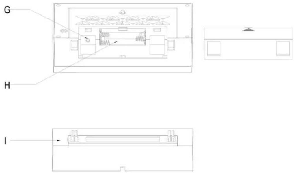
text_image
G H Inatural_image
Diagram of a device showing two connected components with connectors and wiring (no text or symbols)Opmerking
natural_image
Pure mechanical diagram showing a lever system with pulleys and weights, no text or symbols presentnatural_image
Pure mechanical diagram showing a lever mechanism with no text, numbers, or symbolsnatural_image
Pure mechanical assembly diagram without any text, numbers, or symbolstext_image
Aansluingen Comparment RF REMOTE SENSORtext_image
Technical diagram showing a mechanical assembly with labeled components and directional arrows indicating motion or force.natural_image
Diagram of a device showing two connected components with connectors and wiring (no text or symbols)NOTA
natural_image
Pure mechanical diagram showing a lever system with pulleys and weights, no text or symbols presentnatural_image
Pure mechanical diagram showing a lever mechanism with no text, numbers, or symbolsnatural_image
Pure mechanical assembly diagram without any text, numbers, or symbolstext_image
Prese Comparmento NAUN RINO RF REMOTE SENSORtext_image
Technical diagram showing mechanical assembly with labeled components and directional arrows indicating motion or forcenatural_image
Diagram of a device with two ports, one connected to a cable and the other showing internal components (no text or symbols)POZNÁMKA
natural_image
Pure mechanical diagram showing a lever system with pulleys and weights, no text or symbols presentnatural_image
Pure mechanical diagram showing a lever mechanism with no text, numbers, or symbolsnatural_image
Pure mechanical assembly diagram showing a shaft and vertical shaft with no text or symbolsnatural_image
Technical line drawing of a mechanical assembly with spring-loaded components and a separate schematic view (no text or symbols)other
| Time (s) | Value | | :--- | :--- | | 2019 | 24.2 | | 2020 | 67 | | 2021 | 23.3 | | 2022 | 70 | | 2023 | 23.58 | | Peak (day) | 21.2 | | Peak (week) | 15 | | Peak (night) | 1 | | Peak (night) | 5 | | Peak (night) | 10 | | Peak (night) | 12 | | Peak (night) | 10 | | Peak (night) | 12 | | Peak (night) | 10 | | Peak (night) | 12 | | Peak (night) | 10 | | Peak (night) | 12 | | Peak (night) | 10 | | Peak (night) | 12 | | Peak (night) | 10 | | Peak (night) | 10 | | Peak (night) | 12 | | Peak (night) | 10 | | Peak (night) | 12 | | Peak (night) | 10 | | Peak (night) | 10 | | Peak (night) | 12 | | Peak (night) | 10 | | Peak (night) | 10 | | Peak (night) | 12 | | Peak (night) | 10 | | Peak (night) | 10 | | Peak (night) | 12 | | Peak (night) | 10 | | Peak (night) | 12 | | Peak (night) | 10 | | Peak (night) | 10 | | Peak (night) | 10 | | Peak (night) | 12 | | Peak (night) | 10 | | Peak (night) | 10 | | Peak (night) | 12 | | Peak (night) | 10 | | Peak (night) | 10 | | Peak (night) | 12 | | Peak (night) | 12 | | Peak (night) | 10 | | Peak (night) | 10 | | Peak (night) | 12 | | Peak (night) | 10 | | Peak (night) | 10 | | Peak (night) | 12 | | Peak (night) | 10 | | Peak (night) | 10 | | Peak (night) | 10 | | Peak (night) | 12 | | Peak (night) | 10 | | Peak (night) | 10 | | Peak (night) | 12 | | Peak (night) | 12 | | Peak (night) | 10 | | Peak (night) | 10 | | Peak (night) | 10 | | Peak (night) | 12 | | Peak (night) | 10 | | Peak (night) | 10 | | Peak (night) | 10 | | Peak (night) | 12 | | Peak (night) | 10 | | Peak (night) | 10 | | Peak (night) | 10 | | Peak (night) | 12 | | Peak (night) | 12 | | Peak (night) | 10 | | Peak (night) | 10 | | Peak (night) | 10 | | Peak (night) | 12 | | Peak (night) | 12 | | Peak (night) | 10 | | Peak (night) | 10 | | Peak (night) | 10 | | Peak (night) | 10 | | Peak (night) | 12 | | Peak (night) | 12 | | Peak (night) | 10 | | Peak (night) | 10 | | Peak (night) | 10 | | Peak (night) | 10 | | Peak (night) | 10 | | Peak (night) | 12 | | Peak (night) | 12 | | Peak (night) | 10 | | Peak (night) | 10 | | Peak (night) | 10 | | Peak (night) | 12 | | Peak (night) | 10 | | Peak (night) | 12 | | Peak (night) | 12 | | Peak (night) | 10 | | Peak (night) | 10 | | Peak (night) | 10 | | Peak (night) | 12 | | Peak (night) | 12 | | Peak (night) | 10 | | Peak (night) | 12 | | Peak (night) | 12 | | Peak (night) | 10 | | Peak (night) | 10 | | Peak (night) | 10 | | Peak (night) | 12 | | Peak (night) | 12 | | Peak (night) | 12 | | Peak (night) | 10 | | Peak (night) | 12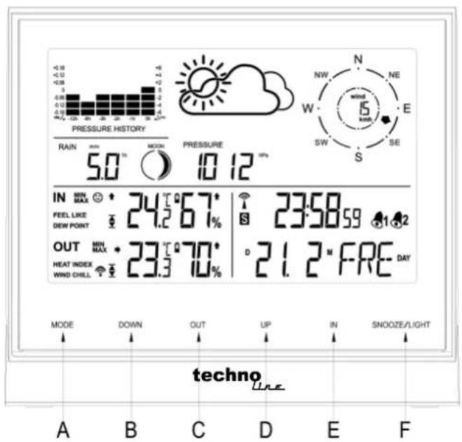
text_image
PRESSURE HISTORY RAIN mm MODE pressure 5.0 10 12 °F IN MIN MAX 24.2°67° S 23:58.59 12 FEEL LIKE DEW POINT OUT MIN MAX 23.3°70° D 21.2°FRE DAY HEAT INDEX WIND CHILL MODE DOWN OUT UP IN SNOOZE/LIGHT techno A B C D E F