WS 7060 - Weather Station TECHNOLINE - Free user manual and instructions
Find the device manual for free WS 7060 TECHNOLINE in PDF.

| Product type | Wireless weather station |
| Brand | TECHNOLINE |
| Model | WS 7060 |
| Indoor temperature range | 0°C to 50°C (32°F to 122°F) |
| Outdoor temperature range | -50°C to 50°C (-58°F to 122°F) |
| Humidity range | 20% to 95% |
| Number of outdoor sensors | Up to 3 (channels OUT-1 to OUT-3) |
| Measurement cycle | Every 30 seconds |
| Station power supply | 2 AAA batteries (not included) |
| Sensor power supply | 2 AAA batteries per sensor (not included) |
| Display | Indoor/outdoor temperature and humidity, min/max values, reception indicator, low battery |
| Special functions | Adjustable temperature alarm (high and low thresholds), max/min recording, °C/°F selection |
| Transmission range | Optimal in open area, may be reduced by obstacles |
| Mounting | Wall mount for station and sensors |
| Operating temperature | Station: 0°C to 50°C; Sensors: -50°C to 50°C |
| Operating humidity | 20% to 95% RH |
| Maintenance precautions | Clean with a soft dry cloth, avoid corrosive products, do not immerse |
| Battery safety | Use only alkaline batteries, observe polarities, do not recharge |
| Repairability | Do not open the housing, no user-serviceable parts |
Frequently Asked Questions - WS 7060 TECHNOLINE
User questions about WS 7060 TECHNOLINE
0 question about this device. Answer the ones you know or ask your own.
Ask a new question about this device
Download the instructions for your Weather Station in PDF format for free! Find your manual WS 7060 - TECHNOLINE and take your electronic device back in hand. On this page are published all the documents necessary for the use of your device. WS 7060 by TECHNOLINE.
USER MANUAL WS 7060 TECHNOLINE
text_image
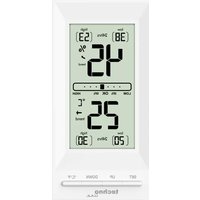
1 2 3 1 2 3 1 2 3 1 2 3 1 4 3 OUT-1 MAX MIN MAX MIN 188.8 88% 5 4 6 OUT-2 MAX MIN MAX MIN 188.8 88% 5 4 6 OUT-3 MAX MIN MAX MIN 188.8 88% 5 4 6 IN MAX / MIN MAX / MIN 188.8 88% 4 6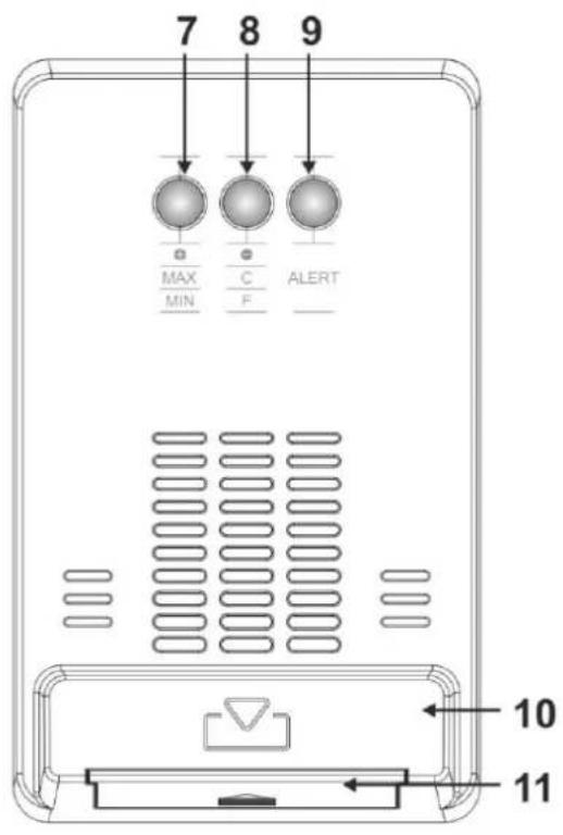
text_image
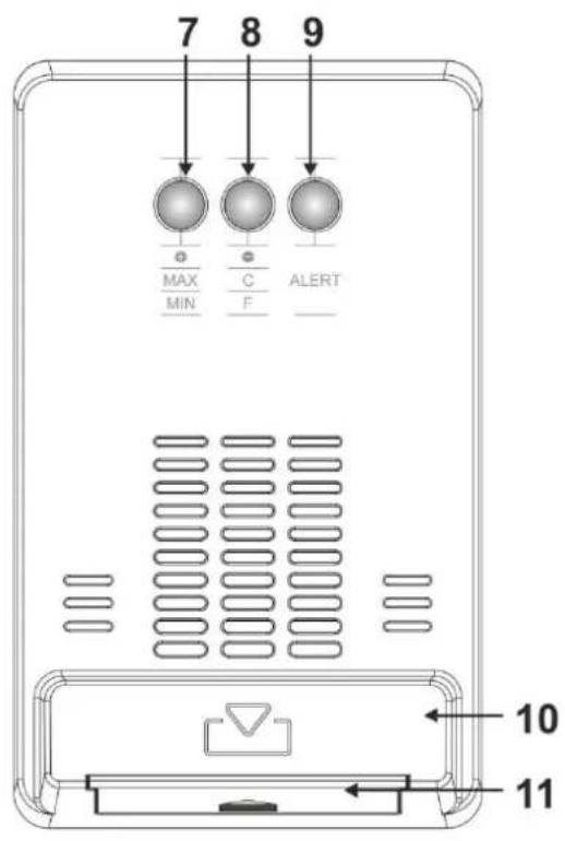
7 8 9 MAX MIN C F ALERT 10 11text_image
1 2 3 1 2 3 1 2 3 1 2 3 1 4 3 OUT-1 MAX MIN 188.0 88% 5 MAX MIN OUT-2 MAX MIN 188.0 88% 5 MAX MIN OUT-3 MAX MIN 188.0 88% 5 MAX MIN OUT-3 MAX / MIN MAX / MIN 188.0 88% 6 MAX / MIN MAX / MIN 4 6 6 4 6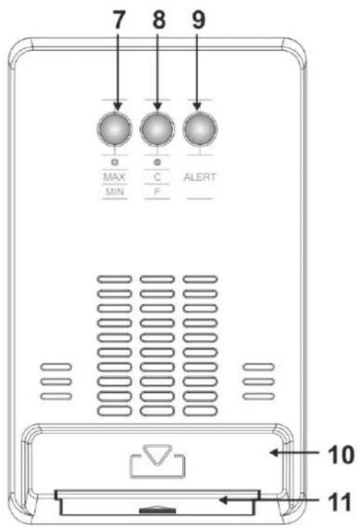
text_image
7 8 9 MAX C ALERT MIN F 10 111 – Channel indicator
3 - Temperature
5 – Sensor reception indicator
7 - + /MAX / MIN button
9 - ALERT button
11 - Battery compartment with battery cover
2 – Alarm symbols with up limit and down limit
4 - Max/Min indicator
6 - Humidity
8 -- / °C / °F button
10 - Stand
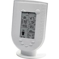
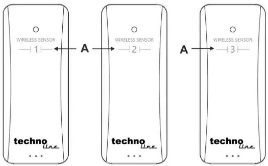
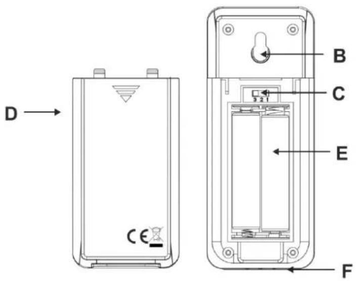
Outdoor sensor
flowchart
graph LR
    subgraph_Device1["Technology Device"]
        direction LR
        A1["Wireless Sensor"] -->|1| A2["Antenna"]
        A2 -->|2| A3["Antenna"]
    end
    subgraph_Device2["Technology Device"]
        direction LR
        A3["Wireless Sensor"] -->|3| A4["Antenna"]
    end
text_image
D → CE B C E FA – Sensor number (same as default channel setting)
C – Channel switch (default set to sensor number)
E – Battery compartment
B – Wall mounting hole
D – Battery cover
F - Stand
Initial operation
- Slide the battery cover off the battery compartment of all sensors and the main station.
- Make sure that the set number on the channel switch is the same as sensor number on front of sensor.
- Insert 2 x AAA batteries into the battery compartment of each of the outdoor sensors.
- Insert 2 x AAA batteries into the battery compartment of the main station.
- Slide the battery cover back onto the battery compartments of all outdoor sensors and the main station.
- When fully powered, the display on the main station will show all symbols for 2 seconds and then change into sensor receiving mode for 3 minutes. Keep the sensors close to the main station until all channels display
- EN02 -
values. Outdoor sensors can be placed away from the main station as soon as all channels are receiving values.
Note:
Should the sensor reception fail after 3 minutes, the reception symbol T_out of the specific channel will disappear. In this case, restart initial operation with a set of fresh and full batteries until all sensors can be connected.
Temperature alarm setting
- In normal display mode, press the Alert button for 3 seconds to enter alert setting mode
- In alert setting mode, press the + or - button to select an outdoor channel.
- Press the Alert button to confirm the selected channel. The down limit symbol ▼ is blinking.
- Press the + or - button to change the value of the down limit.
- Press the Alert button to confirm the alert changes. The up limit symbol ▲ is blinking.
- Press the + or - button to change the value of the up limit.
- Press the Alert button to confirm the alert changes. The up&down limit symbol | ▲ is blinking.
- Press the + or - button to activate the alarm and the alarm symbol 📋 is blinking. Press the + or - button again to deactivate the alarm and alarm symbol 📋 is no longer displayed.
- Press the Alert button to confirm the alert changes and exit the alert setting mode.
Note:
- The alarm symbol will be permanently displayed in the corresponding channel as long as the alarm stays activated.
- Down limit default value is 0 °C, up limit default value is 35°C.
- In alert setting mode, it will be exit when there is no any operation in 20 seconds
- In alert setting mode, press the + or - button once to change value by 1 unit or hold the + or - button to quicker adjust the value.
Temperature alarm
- This station has an up limit & down limit for 3 alarms, one for each outdoor channel.
- If temperature reaches a limit, is higher then up limit or below down limit, then the symbols will flash and the alarm will sound.
or and the

- While alarming, press any button to stop the alarm sound, but the symbol will still be flashing. The alarm sound will also turn off automatically after 1 minute, if no button is pressed.
- The symbol will no longer blink and become permanent again, once the temperature value is no longer at or beyond the set temperature limit.
Note
- The alarm can permanently be deactivated by using the temperature alearm setting.
- EN03 -
Outdoor sensor reception
- While doing initial operation or manual reception, the outdoor reception mode will be entered for 3 minutes and the reception symbol Twall flash.
- Press the – button for 3 seconds to start outdoor reception mode manually.
- The outdoor reception mode was successful once every channel displays values and the reception symbol will be displayed permanently on the display.

Note:
- When sensor data in each channel not receives the same ID code within one hour, the channel will display the last received value flashing, then enter 3 minutes outdoor receiving mode. After one hour, it will clear ID code then enter 3 minutes RF receiving mode, at this time the display in which channel will display --.-, clearing the Max/Min value. It will repeat until a signal is received.
- When the sensor data was lost, but the signal received again, the sensor date will be displayed and the MAX/MIN value recorded
MIN/MAX values
- The lowest and highest values in each channel will be recorded and can be displayed at any time.
- In normal display mode, press the + / MAX / MIN button once to display the MAX values in each channel.
- Press the + / MAX / MIN button once again to display the MIN values.
- Press the + / MAX / MIN button once again to return to normal display mode.
- To clear all recorded values, press the + / MAX / MIN button for 3 seconds and the values on the display will vanish for 1 second to indicate successful MAX/MIN clearing.
Displayed Temperature unit
- In normal display, press the -/C/F button to change the temperature unit between °C and °F.
Temperature and humidity range
- Indoor temperature scope: 32°F\~122°F (0°C\~50°C)
- Testing cycle: 30 seconds
- Outdoor temperature scope: -58°F\~122°F (-50°C\~50°C)
- Indoor/Outdoor humidity scope: 20%\~95%
- When temperature value higher than scope it will display HH.H and when temperature lower than scope it will display LL.L.
- When humidity value higher than scope it will display 95% and when humidity lower than scope it will display 20%.
Low battery indicator
When batteries in outdoor sensors or the main station are starting to run low on energy, the low battery indicator

will be displayed in the corresponding section on the display. This symbol indicates that the batteries in this specific sensor or station should be changed as soon as possible.
Environmental reception effects
Same as all wireless devices, the reception of the station is maybe affected by the following circumstances:
- long transmitting distance
- among tall buildings
• inside concrete buildings - near electrical appliances (computers, TV's, etc) and metallic structures
• inside moving vehicles
Place the station at a location with optimal signal, i.e. close to a window and away from metal surfaces or electrical appliances.
Keep in mind that the outdoor transmitter only has the optimal transmission range in open area with no obstructions. Each obstruction between the transmitter and the station (roof, walls, floors, ceilings, thick trees, etc.) will effectively cut the transmission range in half.
Precautions
- This main unit is intended to be used only indoors.
- Do not subject the unit to excessive force or shock.
- Do not expose the unit to extreme temperatures, direct sunlight, dust or humidity.
- Do not immerse in water.
- Avoid contact with any corrosive materials.
- Do not dispose this unit in a fire as it may explode.
- Do not open the inner back case or tamper with any components of this unit.
Batteries safety warnings
- Use only alkaline batteries, not rechargeable batteries.
• Install batteries correctly by matching the polarities (+/-).
• Always replace a complete set of batteries. - Never mix used and new batteries.
- Remove exhausted batteries immediately.
- Remove batteries when not in use.
- Do not recharge and do not dispose of batteries in fire as the batteries may explode.
- Ensure batteries are stored away from metal objects as contact may cause a short circuit.
- Avoid exposing batteries to extreme temperature or humidity or direct sunlight.
- Keep all batteries out of reach from children. They are a choking hazard.
Use the product only for its intended purpose!
Consideration of duty according to the battery law

Old batteries do not belong to domestic waste because they could cause damages of health and environment. You can return used batteries free of charge to your dealer and collection points. As end-user you are committed by law to bring back needed batteries to distributors and other collecting points!
Consideration of duty according to the law of electrical devices
This symbol means that you must dispose of electrical devices separated from the General household waste when it reaches the end of its useful life. Take your unit to your local waste collection point or recycling centre. This applies to all countries of the European Union, and to other European countries with a separate waste collection system.
text_image
1 2 3 1 2 3 1 2 3 1 2 3 1 4 3 OUT-1 MAX MIN 188.8 | 88% MAX MIN OUT-2 MAX MIN 188.8 | 88% MAX MIN OUT-3 MAX MIN 188.8 | 88% MAX MIN IN MAX / MIN 188.8 | 88% MAX / MIN MAX / MIN 5 4 6 5 4 6 5 4 6 4 6
text_image
7 8 9 MAX MIN C F ALERT 10 11text_image
1 OUT-1 MAX MIN MAX MIN 188.0 88% 5 2 4 3 6 1 OUT-2 MAX MIN MAX MIN 188.0 88% 5 2 4 3 6 1 OUT-3 MAX MIN MAX MIN 188.0 88% 5 2 4 3 6 1 IN MAX / MIN MAX / MIN 188.0 88% 4 4 3 6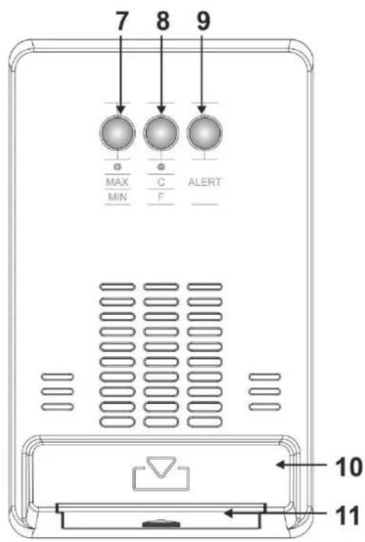
text_image
7 8 9 MAX C ALERT MIN F 10 11text_image
1 2 3 1 2 3 1 2 3 1 2 3 1 4 3 OUT-1 MAX MIN MAX MIN 188.8 88% 5 4 6 OUT-2 MAX MIN MAX MIN 188.8 88% 5 4 6 OUT-3 MAX MIN MAX MIN 188.8 88% 5 4 6 IN MAX / MIN MAX / MIN 188.8 88% 4 6
text_image
7 8 9 MAX C ALERT MIN F 10 11flowchart
graph LR
    A["Wireless Sensor"] -->|1| B["Techno_line"]
    C["Wireless Sensor"] -->|2| D["Techno_line"]
    E["A"] --> F["Techno_line"]
    G["A"] --> H["Techno_line"]

text_image
D → CE B C 3 2 1 E Fflowchart
graph LR
    A["Wireless Sensor"] -->|1| B["Techno_line"]
    C["Wireless Sensor"] -->|2| D["Techno_line"]
    E["A"] --> F["Techno_line"]
    G["A"] --> H["Techno_line"]

text_image
D → CE B C 3 2 1 E Ftext_image
1 OUT-1 MAX MIN MAX MIN 188.0 88% 5 2 4 3 6 1 OUT-2 MAX MIN MAX MIN 188.0 88% 5 2 4 3 6 1 OUT-3 MAX MIN MAX MIN 188.0 88% 5 2 4 3 6 1 IN MAX / MIN MAX / MIN 188.0 88% 4 4 3 6
text_image
7 8 9 MAX C ALERT MIN F 10 11text_image
1 2 3 1 2 3 1 2 3 1 2 3 1 4 3 OUT-1 MAX MIN 188.0 E | 88% MAX MIN OUT-2 MAX MIN 188.0 E | 88% MAX MIN OUT-3 MAX MIN 188.0 E | 88% MAX MIN IN MAX / MIN 188.0 E | 88% MAX / MIN MAX / MIN 5 4 6 5 4 6 5 4 6 4 6