Vnet Ethernet Interface - Speaker Klark Teknik - Free user manual and instructions
Find the device manual for free Vnet Ethernet Interface Klark Teknik in PDF.

User questions about Vnet Ethernet Interface Klark Teknik
0 question about this device. Answer the ones you know or ask your own.
Ask a new question about this device
Download the instructions for your Speaker in PDF format for free! Find your manual Vnet Ethernet Interface - Klark Teknik and take your electronic device back in hand. On this page are published all the documents necessary for the use of your device. Vnet Ethernet Interface by Klark Teknik.
USER MANUAL Vnet Ethernet Interface Klark Teknik
Ethernet Interface for VNET
23Quick Start GuideVNET ETHERNET INTERFACE
EN

Important Safety Instructions

ES
Terminals marked with this symbol carry electrical current of sufficient magnitude to constitute risk of electric shock. Use only high-quality professional speaker cables with 14 " TS or twist-locking plugs pre-installed. All other installation or modification should be performed only by qualified personnel.
This symbol, wherever it appears, alerts you to the presence of uninsulated dangerous voltage inside the enclosure - voltage that may be sufficient to constitute a risk of shock.
This symbol, wherever it appears, alerts you to important operating and maintenance instructions in the accompanying literature. Please read the manual.
Caution To reduce the risk of electric shock, do not remove the top cover (or the rear section). No user serviceable parts inside. Refer servicing to qualified personnel.

Caution
To reduce the risk of fire or electric shock, do not expose this appliance to rain and moisture. The apparatus shall not be exposed to dripping or splashing liquids and no objects filled with liquids, such as vases, shall be placed on the apparatus.

Caution
instructions are for use by qualified service personnel only. To reduce the risk of electric shock do not perform any servicing other than that contained in the operation instructions. Repairs have to be performed by qualified service personnel.
-
Read these instructions.
-
Keep these instructions.
-
Heed all warnings.
-
Follow all instructions.
-
Do not use this apparatus near water.
-
Clean only with dry cloth.
-
Do not block any ventilation openings. Install in accordance with the manufacturer's instructions.
-
Do not install near any heat sources such as radiators, heat registers, stoves, or other apparatus (including amplifiers) that produce heat.
-
Do not defeat the safety purpose of the polarized or grounding-type plug.
A polarized plug has two blades with one wider than the other. A grounding-type plug has two blades and a third grounding prong. The wide blade or the third prong are provided for your safety. If the provided plug does not fit into your outlet, consult an electrician for replacement of the obsolete outlet.
-
Protect the power cord from being walked on or pinched particularly at plugs, convenience receptacles, and the point where they exit from the apparatus.
-
Use only attachments/accessories specified by the manufacturer.

- Use only with the cart, stand, tripod, bracket, or
table specified by the manufacturer, or sold with the apparatus. When a cart is used, use caution when moving the cart/apparatus combination to avoid injury from tip-over.
-
Unplug this app aratus during lightning storms or when unused for long periods of time.
-
Refer all servicing to qualified service personnel. Servicing is required when the apparatus has been damaged in any way, such as power supply cord or plug is damaged, liquid has
been spilled or objects have fallen into the apparatus, the apparatus has been exposed to rain or moisture, does not operate normally, or has been dropped.
-
The apparatus shall be connected to a MAINS socket outlet with a protective earthing connection.
-
Where the MAINS plug or an appliance coupler is used as the disconnect device, the disconnect device shall remain readily operable.

- Correct disposal of this product: This symbol indicates that this
product must not be disposed of with household waste, according to the WEEE Directive (2012/19/EU) and your national law. This product should be taken to a collection center licensed for the recycling of waste electrical and electronic equipment (EEE). The mishandling of this type of waste could have a possible negative impact on the environment and human health due to potentially hazardous substances that are generally associated with EEE. At the same time, your cooperation in the correct disposal of this product will contribute to the efficient use of natural resources. For more information about where you
can take your waste equipment for recycling, please contact your local city office, or your household waste collection service.
-
Do not install in a confined space, such as a book case or similar unit.
-
Do not place naked flame sources, such as lighted candles, on the apparatus.
-
Please keep the environmental aspects of battery disposal in mind. Batteries must be disposed-of at a battery collection point.
-
This apparatus may be used in tropical and moderate climates up to 45°C.
LEGAL DISCLAIMER
Music Tribe accepts no liability for any loss which may be suffered by any person who relies either wholly or in part upon any description, photograph, or statement contained herein. Technical specifications, appearances and other information are subject to change without notice. All trademarks are the property of their respective owners. Midas, Klark Teknik, Lab Gruppen, Lake, Tannoy, Turbosound, TC Electronic, TC Helicon, Behringer, Bugera, Oberheim, Auratone, Aston Microphones and
Coolaudio are trademarks or registered trademarks of Music Tribe Global Brands Ltd. © Music Tribe Global Brands Ltd. 2021 All rights reserved.
LIMITED WARRANTY
For the applicable warranty terms and conditions and additional information regarding Music Tribe's Limited Warranty, please see complete details online at musictribe.com/warranty.

BESCHRÄNKTE GARANTIE
Thank you for choosing this product for your application. Please spare a little time to study the contents of this operation manual, so that you obtain the best possible performance from this unit.
Key Features
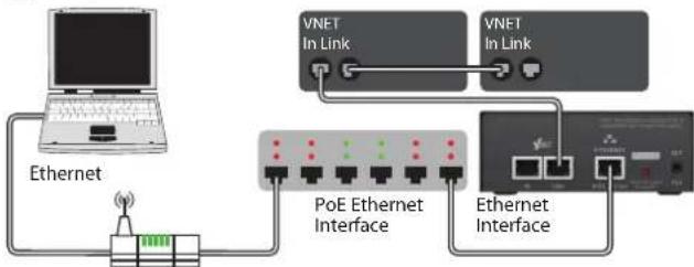
Ethernet is a family of computer networking technologies for local area networks (LANs). Ethernet was commercially introduced in 1980 and standardized in 1985 as IEEE 802.3. Ethernet has largely replaced competing wired LAN technologies. This product allows your Personal Computer access to a network of VNET enabled devices for control and monitoring them. It is connected to your computer or to your network via Ethernet. The three primary ways of connecting your computer to this product are:
- Direct one to one connection (using auto IP)
- Through a switch router or hub
- Through a DHCP router with 802.11g/n for wireless connection
Housed in a convenient, rugged steel case, it can be used free-standing or, using the rack-mount kit, may be racked along with up to two additional accessory products in 1U rack-space.
- Rugged steel enclosure
- Free-standing or rack-mount options
- Self-powered using Power Over Ethernet (PoE)
- Capable of driving 1km of VNET network cable
- No special cables
Computer System Requirements
Minimum requirements:
- PC with >2 GHz processor >2 GB RAM
- 32-bit or 64-bit Windows™ operating system
• (XP, Vista, Windows 7, Windows 8). - CD-ROM drive or Internet access
- Ethernet connection
Installation
Because the Ethernet interface uses Ethernet, no installation of drivers is necessary. However, you will need to check the network settings on your PC, and install the PodWare application in order to control and monitor VNET devices.
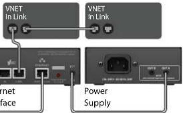
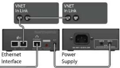
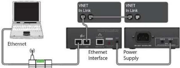
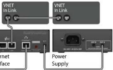
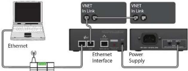
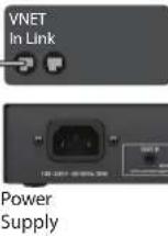
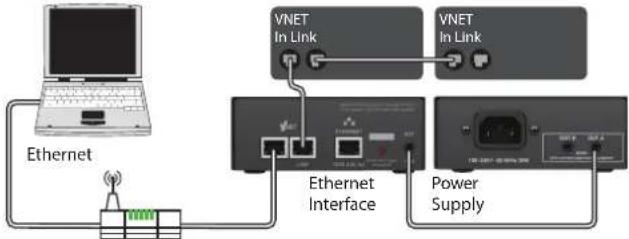
External Power Supply
This product may be powered from a Power Over Ethernet (PoE) Ethernet switch. If such a switch is not available, provision is made to power the unit from an external VNET interface power supply. This can power either one or two compatible accessories. Either the A or the B output on the power supply may be used since these are identical.
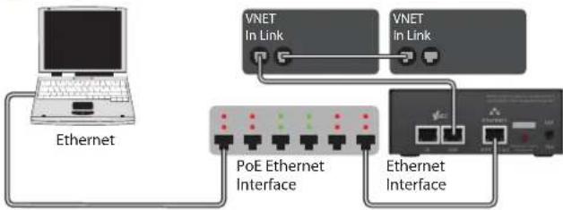
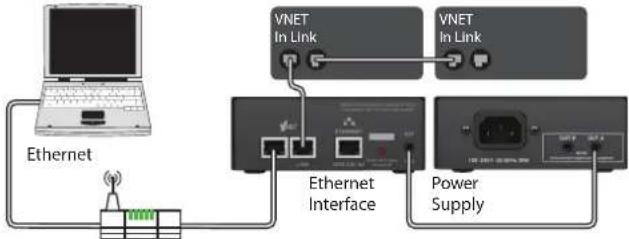
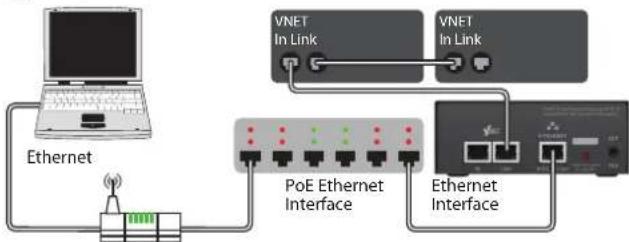
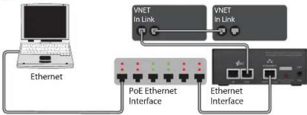
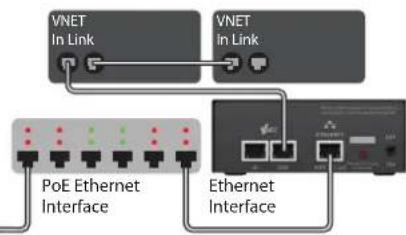
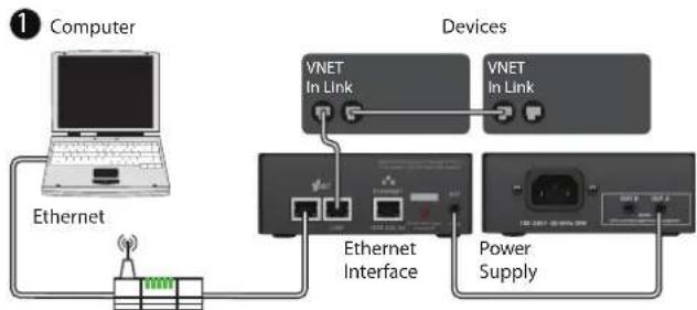
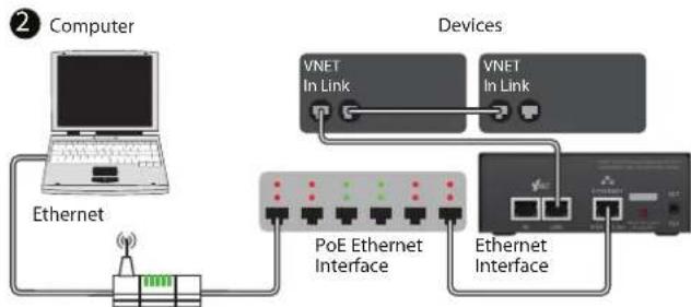
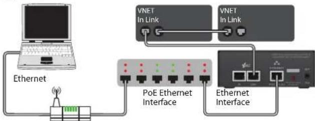
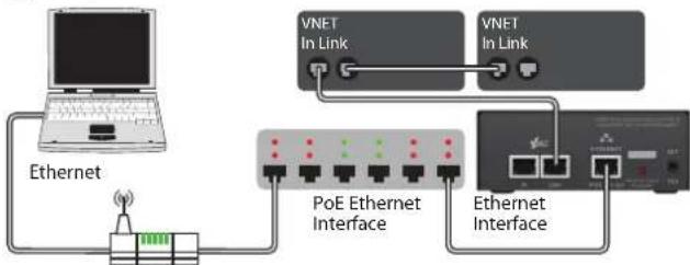
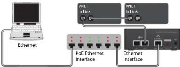
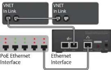
Connecting a Computer
You can connect your computer to the Ethernet interface in one of two ways:
- By direct connection from the Ethernet socket of your computer to the Ethernet interface.
- By connecting your computer to an Ethernet Switch, and from the same switch, or from another switch on the same network, to the Ethernet interface
1
Computer

text_image
Ethernet VNET In Link VNET in Link Ethernet Interface Power Supply2
Computer
flowchart
graph TD
    A["Ethernet"] --> B["PoE Ethernet Interface"]
    B --> C["VNET In Link"]
    B --> D["Ethernet Interface"]
    C --> E["VNET In Link"]
    D --> F["Ethernet Interface"]
Devices
text_image
VNET In Link VNET In Link net Face Power SupplyDevices

flowchart
graph TD
    A["PoE Ethernet Interface"] --> B["VNET In Link"]
    C["Ethernet Interface"] --> D["VNET In Link"]
    B --> E["Output"]
    D --> E
    style A fill:#f9f,stroke:#333
    style C fill:#f9f,stroke:#333
1
Computer
flowchart
graph TD
    A["Ethernet"] --> B["Ethernet"]
    B --> C["VNET In Link"]
    C --> D["Ethernet Interface"]
    D --> E["VNET In Link"]
    E --> F["Power Supply"]
    style A fill:#f9f,stroke:#333
    style B fill:#ccf,stroke:#333
    style C fill:#cfc,stroke:#333
    style D fill:#fcc,stroke:#333
    style E fill:#cff,stroke:#333
    style F fill:#ffc,stroke:#333
2
Computer

flowchart
graph TD
    A["Ethernet"] --> B["PoE Ethernet Interface"]
    B --> C["VNET In Link"]
    B --> D["Ethernet Interface"]
    C --> E["VNET In Link"]
    D --> F["Ethernet Interface"]
You do not need to worry about IP addressing with this product. It will by default use DHCP, so your DHCP server will allocate its IP address. If there is no DHCP Server, it will use "zero config". In either case, it is fully automatic. For more information on this topic, please refer to your network administrator.
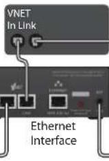
Connecting Devices
For VNET devices, connect the VNET Link socket on the Ethernet Interface to the VNET In socket of the first device you wish to control, then the VNET Link socket of this device to the VNET In socket of the next device, and so on. The order in which the devices are connected is not important. The Link socket of the last device in the 'chain' need not be connected.
Accessory Racking Kit
The Ethernet Interface may be used free-standing or 19" rack mounted using the optional rack mounting kit. This kit comprises of a panel which can accommodate up to three accessories (the Accessory Power Supply being another example) in 1U of rack space. Unused positions are neatly blanked-off. The supplied brackets make the process of mounting the accessories quick and easy.
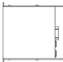
- Remove the two mounting brackets and Lexan blanking sheet which are covering the aperture you wish to mount the accessory in, by removing the two nuts. (Keep these and the screws and washers).
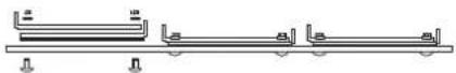
- Remove the two screws from one side of the accessory.
natural_image
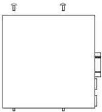
Simple line drawing of a rectangular frame with three corner arrows and a small internal block (no text or symbols)- Using the two screws removed in 2, attach one mounting bracket loosely to the side of the accessory, with the "ear" towards the front, pointing outwards.
natural_image
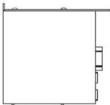
Pure architectural line drawing of a room with walls and doorways (no text or symbols)- Repeat 2 and 3 for the other side. Now push the lid towards the back of the unit as far as it will go then align the bracket ears with the front edge of the lid. Now tighten the screws.
natural_image
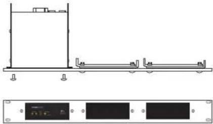
Pure architectural line drawing of a room with walls and a vertical door (no text or symbols)- Offer the accessory with its mounting brackets up to the reverse side of the Mounting Panel, and fix it in place using the two sets of screws, washers and nuts removed in 1.
natural_image
Technical line drawing of a mechanical assembly with mounting holes and a separate panel view below (no text or symbols)Note that the holes at the rear ends of the brackets may be used as cable tie-off points if desired.
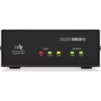
Operation
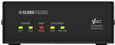
Once the Ethernet Interface has been connected to the computer/Switch and to the devices and if applicable, to the Power Supply, as previously described, then there are no further adjustments to make on the unit itself. The indicators on the front of the unit operate as follows:.
text_image
KLARK T800 POWER VNET ETHERNET SIT PUE DATA LINK ONLINE VNET ETHERNET INTERFACEThe EXT Power indicator will illuminate when DC power is being applied to the EXT Power socket on the rear of the unit.
The PoE Power indicator will illuminate when DC power is being provided by a Power Over Ethernet (PoE) Switch.
The VNET DATA indicator will illuminate when data is being received from the VNET network.
The Ethernet Link indicator will flicker when the unit is connected to an Ethernet network.
The Ethernet Data indicator is used to indicate the following states:
On – Connected to devices via PodWare
- Rapid blinking – In boot
- Rapid brief flashes – Acquiring IP address
- Slow blinking – Locate feature (or button press timeout)
On - Online to PodWare - Brief flash every 5 seconds – in Static IP mode
The Ethernet DATA indicator will illuminate when the unit is receiving control data over Ethernet
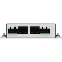
text_image
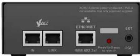
NOTE: External power is required if PCC is not accurate. Use only approved supplies. NET IN LINK ETHERNET EXT Pressure for 3 sec the input PS PSUThe Ethernet RJ45 socket is the Ethernet connection, which should be connected from your computer or Ethernet Switch or Router.
The VNET In RJ45 socket is the serial VNET network connection, which may be used to connect further VNET devices.
The VNET Link RJ45 socket is the primary serial VNET network connection, which should be connected to the first VNET device in your VNET network.
The recessed push button is used to set the IP Addressing mode to the default "Auto" condition by pressing and holding it for about 10 seconds (until the Ethernet Data Indicator flashes. For special maintenance purposes, your vendor may also ask you to enter "Boot" mode by pressing and holding this button while the Interface is powering up.
The Ext 3.5 mm Jack socket is used for applying external power to the Ethernet interface. Use only an approved DC power source. If you are using a PoE Switch, then no connection need be made to this connector.
Trouble Shooting
The EXT Power indicator does not illuminate
If you do not have a connection to a PoE Ethernet Switch, you need to use the Accessory Power Supply.
- Make sure this is connected properly.
- Check if the power indicator on the Power Supply illuminates.
- If instead you are using a PoE Ethernet Switch, it is not usually necessary for an external power supply to be used, in which case this indicator will not illuminate.
PodWare does not find the Interface
- Check that the Ethernet Data indicator flashes to indicate that there is an Ethernet connection.
- Make sure the Ethernet network cable is not too long, is correctly connected, and is not damaged.
- Make sure the Interface does not have a Static IP address.
- Turn off the wireless port on your computer.
- Check if any firewall is blocking PodWare from accessing the network.
PodWare finds no devices
- Can you see a Ethernet Interface Network Bar in PodWare?
- Are the appropriate indicators illuminated? (See above).
- Make sure the VNET network cabling is not too long, is correctly connected, and is not damaged and conforms to Application Note DQ2707.
- Check that the VNET Data indicator flashes when PodWare attempts to go online. If not, there may be a problem with the VNET cabling.
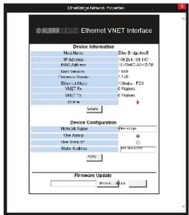
Network Properties
To access the below panel, right click on the Ethernet Interface Network you wish to access and click properties.
text_image
Ethernet VNET Interface Device Information Host Name: 36c-Big-408 IP Address: 59-214-58-143 KNO Address: 1-3465-02-0-0-18 Export Version: 1 GB Firmware Version: 1.129 Ethernet Mode: 100Mbps FDX VNET Rx: 0 Frames VNET Tx: 0 Frames Chrome Update Device Configuration Network Name: FXX-437p Use Asup: Use Select: State Address: FXX-437p Apply Firmware Update Browse...- Device Information displays the Host Name, current IP Address, Firmware/Boot versions, Mac Address and the Online status
- Locate button - The locate button flashes Ethernet data indicator on the Ethernet Interface to show which Ethernet Interface you are online to.
- AutoIP/Static IP radio buttons - Indicates the type of IP addressing and IP address that the static will be set to. Note: Static IP should not normally be used since this could easily result in duplicate IP addresses, addresses out of range, or addresses which are not compatible with your computer settings. Most networks are setup in an ad hoc basis and setting static IP addresses will prevent the DHCP server assigning a known available IP address.
- Apply button - Sets configuration of IP setting and network name changes.
- Firmware Update - Browse to locate update file and click update to load firmware file in to the Ethernet Interface.
32 VNET ETHERNET INTERFACE
Quick Start Guide
Introducción
text_image
Ethernet VNET In Link VNET in Link Ethernet Interface Power SupplyDevices
2
Computer

flowchart
graph TD
    A["Ethernet"] --> B["PoE Ethernet Interface"]
    B --> C["VNET In Link"]
    C --> D["Ethernet Interface"]
    D --> E["VNET In Link"]
1
Computer

flowchart
graph TD
    A["Ethernet"] --> B["Network Switch"]
    B --> C["VNET In Link"]
    C --> D["Ethernet Interface"]
    D --> E["VNET In Link"]
    E --> F["Power Supply"]
    style A fill:#f9f,stroke:#333
    style B fill:#ccf,stroke:#333
    style C fill:#cfc,stroke:#333
    style D fill:#fcc,stroke:#333
    style E fill:#cff,stroke:#333
    style F fill:#ffc,stroke:#333
2
Computer
flowchart
graph TD
    A["Ethernet"] --> B["PoE Ethernet Interface"]
    B --> C["VNET In Link"]
    C --> D["VNET In Link"]
    D --> E["Ethernet Interface"]
    E --> F["PoE Ethernet Interface"]
    F --> G["VNET In Link"]
    G --> H["VNET In Link"]
natural_image
Simple line drawing of a rectangular frame with three corner markers (no text or symbols)natural_image
Pure architectural line drawing of a room with no text, numbers, or symbolsnatural_image
Pure architectural line drawing of a room frame with no text, numbers, or symbolsnatural_image
Technical line drawing of a mechanical assembly with mounting brackets and a separate panel view below (no text or symbols)text_image
NOTE: External power is required if PCC is not accurate. Use only approved supplies. NET IN LINK ETHERNET IEEE 802.3ell EXT Press for 5 sec to include PC PSUtext_image
Ethernet VNET Interface Device Information Host Name: 36c-Big-40e8 IP Address: 59-254-58-143 KNO Address: 1-3465-02-0-0-18 Export Version: 1 GB Firmware Version: 1.129 Ethernet Mode: 100mA FDX VNET Rx: 6 Frames VNET Tx: 6 Frames Chrome: Update Device Configuration Network Name: $77-437m Use Asysp: Use Select: State Address: 912 Net-003? Copyright Firmware Update Browse... ©text_image
Ethernet VNET In Link VNET in Link Ethernet Interface Power Supply2
Computer
flowchart
graph TD
    A["Ethernet"] --> B["PoE Ethernet Interface"]
    B --> C["VNET In Link"]
    C --> D["Ethernet Interface"]
    D --> E["VNET In Link"]
Devices
text_image
VNET In Link VNET in Link Ethernet Interface Power SupplyDevices
flowchart
graph TD
    A["PoE Ethernet Interface"] --> B["VNET In Link"]
    C["Ethernet Interface"] --> D["VNET In Link"]
    B --> E["Port 1"]
    D --> F["Port 2"]
    style A fill:#f9f,stroke:#333
    style C fill:#f9f,stroke:#333
    style B fill:#ccf,stroke:#333
    style D fill:#ccf,stroke:#333
1
Computer
flowchart
graph TD
    A["Ethernet"] --> B["Ethernet"]
    B --> C["VNET In Link"]
    C --> D["Ethernet Interface"]
    D --> E["VNET In Link"]
    E --> F["Power Supply"]
    style A fill:#f9f,stroke:#333
    style B fill:#ccf,stroke:#333
    style C fill:#cfc,stroke:#333
    style D fill:#fcc,stroke:#333
    style E fill:#cff,stroke:#333
    style F fill:#ffc,stroke:#333
2
Computer

flowchart
graph TD
    A["Ethernet"] --> B["PoE Ethernet Interface"]
    B --> C["VNET In Link"]
    C --> D["VNET In Link"]
    D --> E["Ethernet Interface"]
    E --> F["PoE Ethernet Interface"]
    F --> G["VNET In Link"]
    G --> H["VNET In Link"]
natural_image
Simple line drawing of a rectangular frame with three corner markers (no text or symbols)natural_image
Pure architectural line drawing of a room layout with no text, numbers, or symbolsnatural_image
Pure architectural line drawing of a room with walls and a vertical door (no text or symbols)natural_image
Technical line drawing of a structural beam with support beams and a control panel below (no text or symbols)text_image
NOTE: External power is required if PCC is not accurate. Use only approved supplies. NET IN LINK ETHERNET IEEE 802.3ell Ext Press for 5 sec to include PC PSUtext_image
EthernetVNET Interface Device Information Host Name: Etho Bridge408 IP Address: 59.264-159.140 KPC Address: 5-0706-03-0-0-18 Host Version: 1.020 Firmware Version: 1.120 Ethernet Mode: 10Mbps FDX VNET Fix: 6 Frames VNET Tx: 6 Frames Other User Device Configuration Network Name: 77-799 Use Update: Use Static: State Address: 102.16.16.22 Apply Firmware Update Browse...External Power Supply
text_image
1 Computer Ethernet Devices VNET In Link VNET In Link Ethernet Interface Power Supply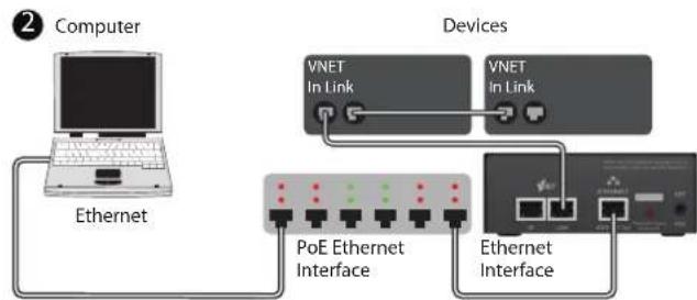
flowchart
graph TD
    A["Computer"] --> B["Ethernet"]
    B --> C["PoE Ethernet Interface"]
    C --> D["Ethernet Interface"]
    D --> E["VNET In Link"]
    E --> F["Devices"]
    style A fill:#f9f,stroke:#333
    style B fill:#ccf,stroke:#333
    style C fill:#cfc,stroke:#333
    style D fill:#fcc,stroke:#333
    style E fill:#ffc,stroke:#333
    style F fill:#cff,stroke:#333
flowchart
graph TD
    A["Computer"] --> B["Ethernet"]
    B --> C["Ethernet"]
    C --> D["VNET In Link"]
    D --> E["Devices"]
    E --> F["VNET In Link"]
    F --> G["Ethernet Interface"]
    G --> H["Power Supply"]
flowchart
graph TD
    A["Computer"] --> B["Ethernet"]
    B --> C["PoE Ethernet Interface"]
    C --> D["Devices"]
    D --> E["VNET In Link"]
    D --> F["VNET In Link"]
    C --> G["Ethernet Interface"]
    G --> H["Device"]
natural_image
Simple line drawing of a rectangular frame with three corner markers (no text or symbols)natural_image
Pure architectural line drawing of a room with no text, numbers, or symbolsnatural_image
Pure architectural line drawing of a room with horizontal beams and vertical supports (no text or symbols)natural_image
Pure architectural or engineering line drawing showing a vertical structure with horizontal supports and a small rectangular component, no text or symbols present.
text_image
NOTE: External power is required if PCC is not accurate. Use only approved supplies. NET IN LINK ETHERNET IEEE 802.3ell Ext Press for 3 sec to include PC PSUThe Ext 3.5 mm Jack socket is used for applying external power to the Ethernet interface. Use only an approved DC power source. If you are using a PoE Switch, then no connection need be made to this connector.
Fehlerbehebung
text_image
Ethernet VNET Interface Device Information Host Name: Ether IP 10018 IP Address: 194.254.103.140 MAC Address: 15.506.262.40-43-18 Boot Working: 1.050 Firmware Worker: 1.120 Ethernet Mode: 120mba - FDX VNET IP: 6 frames VNET IP: 6 frames Other: Device Configuration Network Name: 74e-323p User Address: * User Busik IP: 0 Static Outages: $25,168,000 Apply: Firmware Update Remove...text_image
Ethernet VNET In Link VNET in Link Ethernet Interface Power Supply2
Computer

flowchart
graph TD
    A["Ethernet"] --> B["PoE Ethernet Interface"]
    B --> C["VNET In Link"]
    C --> D["Ethernet Interface"]
    D --> E["VNET In Link"]
Devices
text_image
VNET In Link VNET In Link net Face Power SupplyDevices

flowchart
graph TD
    A["VNET In Link"] --> B["PoE Ethernet Interface"]
    C["VNET In Link"] --> D["Ethernet Interface"]
    B --> E["Switch"]
    D --> F["Switch"]
    style A fill:#f9f,stroke:#333
    style C fill:#f9f,stroke:#333
    style B fill:#ccf,stroke:#333
    style D fill:#ccf,stroke:#333
1
Computer
flowchart
graph TD
    A["Ethernet"] --> B["Ethernet"]
    B --> C["VNET In Link"]
    C --> D["Ethernet Interface"]
    D --> E["VNET In Link"]
    E --> F["Power Supply"]
    style A fill:#f9f,stroke:#333
    style B fill:#ccf,stroke:#333
    style C fill:#cfc,stroke:#333
    style D fill:#fcc,stroke:#333
    style E fill:#cff,stroke:#333
    style F fill:#ffc,stroke:#333
2
Computer
flowchart
graph TD
    A["Ethernet"] --> B["PoE Ethernet Interface"]
    B --> C["VNET In Link"]
    B --> D["Ethernet Interface"]
    C --> E["VNET In Link"]
    D --> F["Ethernet Interface"]
Devices


natural_image
Simple line drawing of a rectangular frame with three corner connectors (no text or symbols)natural_image
Pure architectural line drawing of a room with no text, numbers, or symbolsnatural_image
Pure architectural line drawing of a room with horizontal beams and vertical supports (no text or symbols)natural_image
Architectural or engineering diagram showing a structural beam with supports and a separate panel with three black rectangular panels below (no text or symbols)text_image
NOTE: External power is required if PCC is not accurate. Use only approved supplies. NET IN LINK ETHERNET IEEE 802.3ell EXT Press for 5 sec to include PC PSU- PC with >2 GHz processor >2 GB RAM
- 32-bit or 64-bit Windows™ operating system
• (XP, Vista, Windows 7, Windows 8). - CD-ROM drive or Internet access
- Ethernet connection
Installazione
text_image
Ethernet VNET In Link VNET in Link Ethernet Interface Power Supply2
Computer

flowchart
graph TD
    A["Ethernet"] --> B["PoE Ethernet Interface"]
    B --> C["VNET In Link"]
    C --> D["Ethernet Interface"]
    D --> E["VNET In Link"]
Devices

text_image
VNET In Link VNET In Link net Face Power SupplyDevices

flowchart
graph TD
    A["VNET In Link"] --> B["PoE Ethernet Interface"]
    C["VNET In Link"] --> D["Ethernet Interface"]
    B --> E["Switch"]
    D --> F["Switch"]
    style A fill:#f9f,stroke:#333
    style C fill:#f9f,stroke:#333
    style B fill:#ccf,stroke:#333
    style D fill:#ccf,stroke:#333
1
Computer

flowchart
graph TD
    A["Ethernet"] --> B["Ethernet"]
    B --> C["VNET In Link"]
    C --> D["Ethernet Interface"]
    D --> E["VNET In Link"]
    E --> F["Power Supply"]
    style A fill:#f9f,stroke:#333
    style B fill:#ccf,stroke:#333
    style C fill:#cfc,stroke:#333
    style D fill:#fcc,stroke:#333
    style E fill:#cff,stroke:#333
    style F fill:#ffc,stroke:#333
2
Computer
flowchart
graph TD
    A["Ethernet"] --> B["PoE Ethernet Interface"]
    B --> C["VNET In Link"]
    C --> D["VNET In Link"]
    D --> E["Ethernet Interface"]
    E --> F["PoE Ethernet Interface"]
    F --> G["VNET In Link"]
    G --> H["VNET In Link"]
Devices
natural_image
Simple line drawing of a rectangular frame with three corner markers (no text or symbols)natural_image
Pure architectural line drawing of a room with no text, numbers, or symbolsnatural_image
Pure architectural line drawing of a room with walls and a vertical door (no text or symbols)natural_image
Architectural or engineering diagram showing structural components and a separate panel with three black rectangular blocks (no text or symbols)text_image
NOTE: External power is required if PCC is not accurate. Use only approved supplies. NET IN LINK ETHERNET IEEE 802.3ell EXT Press for 5 sec to include PC PSUtext_image
EthernetVNET Interface Device Information Host Name: Etho Bridge408 IP Address: 59.264-159.140 KPC Address: 5-0766-03-0-0-18 Host Version: 1.020 Hardware Version: 1.120 Ethernet Mode: 10Mbps FDX VNET Fix: 6 Frames VNET Tx: 6 Frames Other User Device Configuration Network Name: 77-799 Use Update: Use Static IP: State Address: 102.16.16.02 Apply Firmware Update Browse...text_image
Ethernet VNET In Link VNET In Link Ethernet Interface Power Supply2
Computer
flowchart
graph TD
    A["Ethernet"] --> B["PoE Ethernet Interface"]
    B --> C["VNET In Link"]
    C --> D["VNET In Link"]
    D --> E["Ethernet Interface"]
    E --> F["PoE Ethernet Interface"]
    F --> G["VNET In Link"]
1
Computer
flowchart
graph TD
    A["Ethernet"] --> B["Internet"]
    B --> C["VNET In Link"]
    C --> D["Ethernet Interface"]
    D --> E["VNET In Link"]
    E --> F["Power Supply"]
    style A fill:#f9f,stroke:#333
    style B fill:#ccf,stroke:#333
    style C fill:#cfc,stroke:#333
    style D fill:#fcc,stroke:#333
    style E fill:#cff,stroke:#333
    style F fill:#ffc,stroke:#333
2
Computer
flowchart
graph TD
    A["Ethernet"] --> B["PoE Ethernet Interface"]
    B --> C["VNET In Link"]
    C --> D["VNET In Link"]
    D --> E["Ethernet Interface"]
    E --> F["PoE Ethernet Interface"]
    F --> G["VNET In Link"]
    G --> H["VNET In Link"]
natural_image
Simple line drawing of a rectangular frame with three corner markers (no text or symbols)natural_image
Pure architectural line drawing of a room with no text, numbers, or symbolsnatural_image
Pure architectural line drawing of a room with walls and a vertical structure (no text or symbols)natural_image
Pure architectural line drawing of a two-story building with railings and a vertical structure (no text or symbols)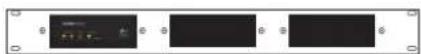
text_image
NOTE: External power is required if PCC is not accurate. Use only approved supplies. NET IN LINK ETHERNET IEEE 802.3ell Ext Press for 5 sec to include PC PSUtext_image
Ethernet VNET In Link VNET in Link Ethernet Interface Power SupplyDevices
2
Computer

flowchart
graph TD
    A["Ethernet"] --> B["PoE Ethernet Interface"]
    B --> C["VNET In Link"]
    C --> D["Ethernet Interface"]
    D --> E["VNET In Link"]
1
Computer

flowchart
graph TD
    A["Ethernet"] --> B["Ethernet"]
    B --> C["VNET In Link"]
    C --> D["Ethernet Interface"]
    D --> E["VNET In Link"]
    E --> F["Power Supply"]
    style A fill:#f9f,stroke:#333
    style B fill:#ccf,stroke:#333
    style C fill:#cfc,stroke:#333
    style D fill:#fcc,stroke:#333
    style E fill:#cff,stroke:#333
    style F fill:#ffc,stroke:#333
2
Computer

flowchart
graph TD
    A["Ethernet"] --> B["PoE Ethernet Interface"]
    B --> C["VNET In Link"]
    C --> D["VNET In Link"]
    D --> E["Ethernet Interface"]
    E --> F["PoE Ethernet Interface"]
    F --> G["VNET In Link"]
    G --> H["VNET In Link"]
natural_image
Simple line drawing of a rectangular frame with three upward arrows on top and a small vertical bar on the right side (no text or symbols)natural_image
Pure architectural line drawing of a room with no text, numbers, or symbolsnatural_image
Pure architectural line drawing of a room with walls and a vertical door (no text or symbols)natural_image
Technical line drawing of a mechanical assembly with mounting brackets and a separate panel view (no text or symbols)text_image
NOTE: External power is required if PCC is not accurate. Use only approved supplies. NET IN LINK ETHERNET IEEE 802.3ell EXT Press for 5 sec to include PC PSUtext_image
Ethernet VNET In Link VNET in Link Ethernet Interface Power Supply2
Computer

flowchart
graph TD
    A["Ethernet"] --> B["PoE Ethernet Interface"]
    B --> C["VNET In Link"]
    C --> D["Ethernet Interface"]
    D --> E["VNET In Link"]
Devices

text_image
VNET In Link VNET In Link net Face Power SupplyDevices
flowchart
graph TD
    A["VNET In Link"] --> B["PoE Ethernet Interface"]
    C["VNET In Link"] --> D["Ethernet Interface"]
    B --> E["Switch"]
    D --> F["Switch"]
1
Computer

flowchart
graph TD
    A["Ethernet"] --> B["Ethernet"]
    B --> C["VNET In Link"]
    C --> D["Ethernet Interface"]
    D --> E["VNET In Link"]
    E --> F["Power Supply"]
    style A fill:#f9f,stroke:#333
    style B fill:#ccf,stroke:#333
    style C fill:#cfc,stroke:#333
    style D fill:#fcc,stroke:#333
    style E fill:#cff,stroke:#333
    style F fill:#ffc,stroke:#333
2
Computer

flowchart
graph TD
    A["Ethernet"] --> B["PoE Ethernet Interface"]
    B --> C["VNET In Link"]
    C --> D["VNET In Link"]
    D --> E["Ethernet Interface"]
    E --> F["PoE Ethernet Interface"]
    F --> G["VNET In Link"]
    G --> H["VNET In Link"]
natural_image
Simple line drawing of a rectangular frame with three corner markers (no text or symbols)natural_image
Pure architectural line drawing of a room layout with no text, numbers, or symbolsnatural_image
Pure architectural line drawing of a room with walls and a vertical door (no text or symbols)natural_image
Technical line drawing of a mechanical assembly with mounting brackets and a separate panel view below (no text or symbols)Quick Start Guide109
Operacja
text_image
NOTE: External power is required if PCC is not accurate. Use only approved supplies. NET IN LINK ETHERNET IEEE 802.3ell Ext Press for 3 sec to include PC PSU| Ethernet | |
| Speed 100/1000 base T | |
| Connector Standard RJ45 | |
| VNETTM | |
| Cable type Category 5 UTP (or better) | |
| Max. total cable length 1 km | |
| Max. Network Span 1 km | |
| Connector Standard RJ45 | |
| External Power | |
| Klark Teknik VNET Power Supply (via 3.5 mm cable) or Power-over Ethernet | |
| Power consumption | |
| Power-over-Ethernet 5 W max | |
| Externally powered 15 V | |
| Environmental | |
| Temperature 0 to +45°C | |
| Humidity 0 to 80% RH (non-condensing) | |
| Physical | |
| Dimensions 45 x 117 x 117 mm (1.8 x 4.6 x 4.6") | |
| Weight 0.5 kg (1.1 lbs) | |
Notes:
Use only approved power supplies.
A full range of measurements, performance data, can be downloaded from klarkteknik.com. For project-specific system design assistance, contact the AET group via www.aetgroup.tc
Klark Teknik operates a policy of continuous research and development. The introduction of new materials or manufacturing methods will always equal or exceed the published specifications. All specifications are subject to change without notice
VNET is a trademark of Klark Teknik. All other trademarks remain the property of their respective owners.
114 115 Quick Start GuideVNET ETHERNET INTERFACE
Other important information

Important information

Please register your new Music Tribe equipment right after you purchase it by visiting musictribe.com. Registering your purchase using our simple online form helps us to process your repair claims more quickly and efficiently. Also, read the terms and conditions of our warranty, if applicable.
- Malfunction, Should your Music Tribe Authorized Reseller not be located in your vicinity, you may contact the Music Tribe Authorized Fulfiller for your country listed under "Support" at musictribe.com. Should your country not be listed, please check if your problem can be dealt with by our "Online Support" which may also be found under "Support" at musictribe.com. Alternatively, please submit an online warranty claim at musictribe.com BEFORE returning the product.
3. Power Connections.
Before plugging the unit into a power socket, please make sure you are using the correct mains voltage for your particular model. Faulty fuses must be replaced with fuses of the same type and rating without exception.
1. Registro online.
Other important information

1. Registreer online.
Responsible Party Name: Music Tribe Commercial NV Inc.
Address: 5270 Procyon Street,
Las Vegas NV 89118,
United States
Phone Number: +1 702 800 8290
VNET ETHERNET INTERFACE
This equipment has been tested and found to comply with the limits for a Class A digital device, pursuant to part 15 of the FCC Rules. These limits are designed to provide reasonable protection against harmful interference when the equipment is operated in a commercial environment. This equipment generates, uses, and can radiate radio frequency energy and, if not installed and used in accordance with the instruction manual, may cause harmful interference to radio communications. Operation of this equipment in a residential area is likely to cause harmful interference in which case the user will be required to correct the interference at his own expense.
• Reorient or relocate the receiving antenna.
- Increase the separation between the equipment and receiver.
- Connect the equipment into an outlet on a circuit different from that to which the receiver is connected.
- Consult the dealer or an experienced radio/TV technician for help.
This device complies with Part 15 of the FCC rules.
Operation is subject to the following two conditions:
(1) this device may not cause harmful
interference, and
(2) this device must accept any interference
received, including interference that may cause
undesired operation.
Important information:
Changes or modifications to the equipment not expressly approved by Music Tribe can void the user's authority to use the equipment.

Hereby, Music Tribe declares that this product is in compliance with Directive 2014/30/EU, Directive 2011/65/EU and Amendment 2015/863/EU, Directive 2012/19/EU, Regulation 519/2012 REACH SVHC and Directive 1907/2006/EC.
Full text of EU DoC is available at
https://community.musictribe.com/
EU Representative: Music Tribe Brands DK A/S
Address: Ib Spang Olsens Gade 17, DK - 8200 Aarhus
N, Denmark