Qflex Isolator - Speaker Klark Teknik - Free user manual and instructions
Find the device manual for free Qflex Isolator Klark Teknik in PDF.

| Product type | VNET network isolator |
| Brand | Klark Teknik |
| Model | Qflex Isolator |
| Category | Speaker |
| Power supply | 12 V DC, 100 mA per isolator |
| Power consumption | 100 mA |
| Ports | 3 ports (IN, OUT, LINK) with RJ45 connectors and Phoenix terminal blocks |
| Isolation | Galvanic, supports ground potentials up to ±15 V |
| Mounting | Panel mount, 4 mm holes, pitch 40 x 92.5 mm |
| Enclosure | Galvanized steel |
| Use | VNET networks, star topology, noise and interference attenuation |
| Protection | Against wiring faults and ground surges |
| Operating temperature | 45 °C max, tropical or moderate climate |
| External power supply | Required for multiple isolators |
| Wiring | Screw terminal or RJ45 |
| Maximum network length | 1 km per backbone |
| Max number of VNET products | 32 per network |
| Maintenance | Clean with a dry cloth |
| Safety | Do not open, repair by qualified personnel |
| Repairability | No user-serviceable parts |
| Warranty | Limited, see musictribe.com |
Frequently Asked Questions - Qflex Isolator Klark Teknik
User questions about Qflex Isolator Klark Teknik
0 question about this device. Answer the ones you know or ask your own.
Ask a new question about this device
Download the instructions for your Speaker in PDF format for free! Find your manual Qflex Isolator - Klark Teknik and take your electronic device back in hand. On this page are published all the documents necessary for the use of your device. Qflex Isolator by Klark Teknik.
USER MANUAL Qflex Isolator Klark Teknik
text_image
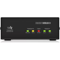
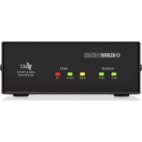
Image of an electronic device with visible label and port connections, showing Chinese text and symbols.QFLEX ISOLATOR
Isolation Module for QFLEX Column Loudspeakers
EN
EN
Important Safety
Instructions
text_image
CAUTION RISK OF ELECTRIC SHOCK! DO NOT OPEN! ATTENTION RISQUE D'ÉLECTROCUTION ! NE PAS OUVRIR !
Uwaga
natural_image
Symbolic icon of a person climbing a ladder inside a circle (no text or symbols)BESCHRÄNKTE GARANTIE
natural_image
Symbolic icon of a person pushing a large object through a circular frame (no text or symbols)ISOLATOR has been designed to ease the problems often presented when large VNET systems are constructed. Specifically it addresses the following issues:
- The possibility that mains earth potentials exceeding +/-15V exists between different network nodes
- Large amounts of electrical noise and interference may be present on the network cables
- Wiring faults on the network cable damaging other network nodes
- It is desired to create networks that have a large "star" topology
- It is desired to use screw terminal terminated wiring to construct the network
- It is desired to be able to install and test the main "backbone" network cable without the presence of other equipment (including ISOLATORS)
As its name implies ISOLATOR limits these problems by making it possible to galvanically isolate different parts of the network from each other and from the controlling computer system. When any of the above situations can be anticipated then ISOLATORS should be incorporated in to the design of the network.
For systems which incorporate AES3 over VNET (VNET2), please contact you vendor for details of how to set the internal jumpers inside the Isolator. Please be aware that some of the application examples shown in this document are not applicable to VNET2 systems.
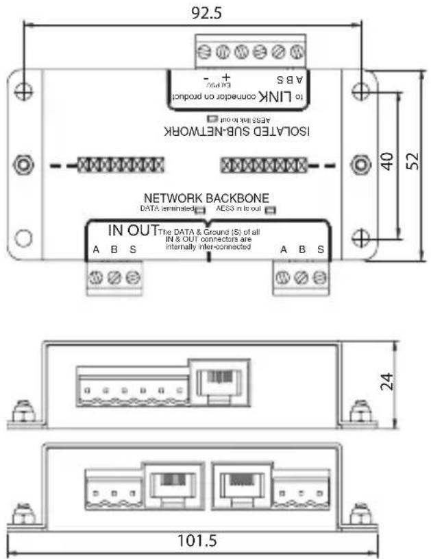
Mounting
ISOLATOR is housed in a strong galvanised steel case that can be mounted using 4 mm diameter hardware in the holes that are on 40 x 92.5 mm centres. If dust or moisture resistance is required then it will be necessary to mount ISOLATOR in a suitable enclosure. Note that the case of ISOLATOR is connected to the earth system on the LINK side of the isolation barrier.
text_image
92.5 A B S + + LINK connector on product ASRS not to out ISOLATED SUB-NETWORK NETWORK BACKBONE DATA terminated AES3 in to out IN OUT The DATA & Ground (S) of all IN & OUT connectors are internally interconnected A B S 24 101.5Connections

ISOLATOR has three ports: IN; OUT & LINK. Each port has both RJ45 and "Phoenix" pluggable screw terminal blocks. These connectors are connected directly together so either may be used as convenient.
For example it might be most convenient to connect ISOLATOR "LINK" to the LINK output of a VNET device using a standard RJ45 patch lead while using the Phoenix connections for the hard wired network "backbone" cabling on the IN and OUT ports (which are also connected directly together).
Power
ISOLATOR is powered via its LINK port. As the LINK port on VNET products provides a source of suitable power, connecting the LINK of ISOLATOR to the LINK of the VNET device with an RJ45 patch cable will power it up.
If the connection from the VNET product is to use the LINK Phoenix connector of the ISOLATOR then the following connections need to be made:
VNET Cat5 Cable and RJ45 Connections
| PIN PAIR COLOUR (T568B) | Product Link | Isolator Link | |||
| 1 | 2 |  | white/orange | data + LINK A | |
| 2 2 orange dat |  | CB | |||
| 3 | 3 |  | white/green | No Connection | |
| 4 1 blue |  | power out + | Ext PSU + | ||
| 5 | 1 |  | white/blue | power out - | Ext PSU - |
| 6 3 green No C |  on on | ||||
| 7 | 4 |  | white/brown | No Connection | |
| 8 4 brown No C |  ion ion | ||||
If a screen cable is used, connect the screen to LINK S
As VNET products can only supply enough power for a single ISOLATOR, systems requiring more than one will need an external power supply. In this case no connection should be made between the VNET product and the "Ext PSU" connections of ISOLATOR, these connections should be used for the external power supply.
External supplies should produce regulated 12V DC with at least 100mA available for each ISOLATOR that is to be supplied. Klark Teknik can supply or recommend a suitable power supply.
If the VNET product is connected to the ISOLATOR via its RJ45 connector then as described above this will automatically connect the power from the product's LINK port to the ISOLATOR. This is not a concern because ISOLATOR contains circuitry to prevent any conflict with an external power supply.
Configurations
For maximum flexibility ISOLATOR can be used in a number of ways, below are some examples:
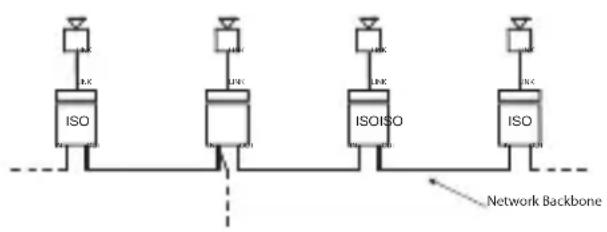
- Basic IN to OUT daisy-chaining with additional branches as required.
flowchart
graph TD
    A["ISO"] --> B["IJK"]
    C["ISO"] --> D["IJK"]
    E["ISO"] --> F["IJK"]
    G["ISO"] --> H["IJK"]
    I["ISO"] --> J["IJK"]
    K["Network Backbone"] --> L["Network Backbone"]
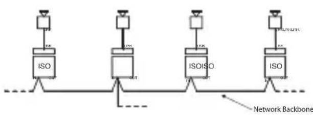
- Using only the Phoenix IN (or OUT) ports allows the network wiring to be installed and tested before other equipment is installed.
flowchart
graph TD
    A["ISO"] --> B["Network Backbone"]
    C["ISO"] --> D["Network Backbone"]
    E["ISO"] --> F["Network Backbone"]
    G["ISO"] --> H["Network Backbone"]
    I["ISO"] --> J["Network Backbone"]
    K["ISO"] --> L["Network Backbone"]
    M["ISO"] --> N["Network Backbone"]
    O["ISO"] --> P["Network Backbone"]
    Q["ISO"] --> R["Network Backbone"]
    S["ISO"] --> T["Network Backbone"]
    U["ISO"] --> V["Network Backbone"]
    W["ISO"] --> X["Network Backbone"]
    Y["ISO"] --> Z["Network Backbone"]
- ISOLATORs may be used to segment a large network as convenient, protecting each segment from the others. Note that using them in this way does NOT allow the network to exceed the 1 km total maximum length limit.

flowchart
graph LR
    A["USB Interface"] --> B["IO"]
    B --> C["ISO"]
    C --> D["Output"]
    style A fill:#f9f,stroke:#333
    style B fill:#ccf,stroke:#333
    style C fill:#cfc,stroke:#333
    style D fill:#fcc,stroke:#333
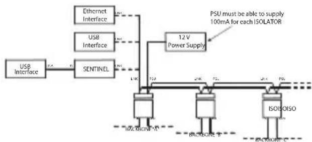
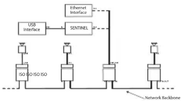
- Here multiple ISOLATORS are used to create multiple backbones. As long as the ISOLATORS are local to each other and the controlling system, then each backbone may be the full 1 km long.
Note that the maximum number of VNET products per network (not per backbone) remains 32.

flowchart
graph TD
    A["USB Interface"] --> B["SentINEL"]
    B --> C["12V Power Supply"]
    C --> D["ISOISOISO"]
    D --> E["Backbone - A"]
    D --> F["Backbone - B"]
    D --> G["Backbone - C"]
    H["Ethernet Interface"] --> I["12V Power Supply"]
    J["USB Interface"] --> K["12V Power Supply"]
    L["PSU must be able to supply 100mA for each ISOLATOR"]
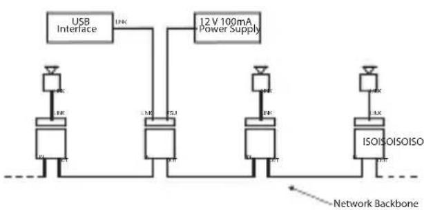
- Because of the limited power available from a USB interface, connecting the USB interface directly to an ISOLATOR will not work unless an external power supply is connected either to the rear of the USB interface or, as shown, to the ISOLATOR.
flowchart
graph TD
    A["USB Interface"] --> B["12V 100mA Power Supply"]
    B --> C["ISOISOISOISO"]
    C --> D["Network Backbone"]
    style A fill:#f9f,stroke:#333
    style B fill:#ccf,stroke:#333
    style C fill:#cfc,stroke:#333
    style D fill:#fcc,stroke:#333
- Both Klark Teknik's SENTINEL and Ethernet interface can provide sufficient power for one ISOLATOR.
flowchart
graph TD
    A["USB Interface"] -->|R1| B["SENTINEL"]
    B -->|R2| C["Network Backbone"]
    D["ISO ISO ISO ISO"] --> E["Network Backbone"]
    F["Ethernet Interface"] -->|R3| G["SentINEL"]
    G -->|R4| H["Network Backbone"]
    I["Network Backbone"] --> J["SentINEL"]
    K["Network Backbone"] --> L["SentINEL"]
Introduction
| Performance | |
| Maximum voltage between LINK and IN/OUT | 1kV AC or DC |
| Data protocol and format | OSNET over VNET |
| Maximum length of IN / OUT CAT5 backbone cable | 1000m |
| Power requirement 12V DC <100mA | |
| Environmental protection | IP40 |
| Weight 0.16 kg | |
| Dimensions | 24 x 102 x 52 mm(0.9 x 4 x 2") |
EN Important information
- Register online. Please register your new Music Tribe equipment right after you purchase it by visiting musictribe.com. Registering your purchase using our simple online form helps us to process your repair claims more quickly and efficiently. Also, read the terms and conditions of our warranty, if applicable.
- Malfunction. Should your Music Tribe Authorized Reseller not be located in your vicinity, you may contact the Music Tribe Authorized Fulfiller for your country listed under "Support" at musictribe.com. Should your country not be listed, please check if your problem can be dealt with by our "Online Support" which may also be found under "Support" at musictribe.com. Alternatively, please submit an online warranty claim at musictribe.com BEFORE returning the product.
- Power Connections. Before plugging the unit into a power socket, please make sure you are using the correct mains voltage for your particular model. Faulty fuses must be replaced with fuses of the same type and rating without exception.
Responsible Party Name: Music Tribe Commercial NV Inc.
Address: 5270 Procyon Street,
Las Vegas NV 89118,
United States
Phone Number: +1 702 800 8290
QFLEX ISOLATOR
This equipment has been tested and found to comply with the limits for a Class A digital device, pursuant to part 15 of the FCC Rules. These limits are designed to provide reasonable protection against harmful interference when the equipment is operated in a commercial environment. This equipment generates, uses, and can radiate radio frequency energy and, if not installed and used in accordance with the instruction manual, may cause harmful interference to radio communications. Operation of this equipment in a residential area is likely to cause harmful interference in which case the user will be required to correct the interference at his own expense.
- Reorient or relocate the receiving antenna.
- Increase the separation between the equipment and receiver.
- Connect the equipment into an outlet on a circuit different from that to which the receiver is connected.
- Consult the dealer or an experienced radio/TV technician for help.
This device complies with Part 15 of the FCC rules. Operation is subject to the following two conditions:
(1) this device may not cause harmful interference, and (2) this device must accept any interference received, including interference that may cause undesired operation.
Important information:
Changes or modifications to the equipment not expressly approved by Music Tribe can void the user's authority to use the equipment.

Hereby, Music Tribe declares that this product is in compliance with Hereby, Music Tribe declares that this product is in compliance with Directive 2014/30/EU, Directive 2011/65/EU and Amendment 2015/863/EU, Directive 2012/19/EU, Regulation 519/2012 REACH SVHC and Directive 1907/2006/EC.
Full text of EU DoC is available at https://community.musictribe.com/
EU Representative: Music Tribe Brands DK A/S
Address: Ib Spang Olsens Gade 17, DK - 8200 Aarhus N, Denmark