
WAP124125 - Access Point DELL - Free user manual and instructions
Find the device manual for free WAP124125 DELL in PDF.
| Product type | Wireless access point |
| Brand | Dell |
| Model | WAP124125 |
| Dimensions (HxWxD) | 12.4 x 13 x 5.1 cm (antennas folded) |
| Weight | 0.42 kg |
| Operating temperature | 0 to 50°C |
| Relative humidity | 5 to 95% non-condensing |
| Power | PoE IEEE 802.3af (48 V DC, 350 mA) or 5 V DC power adapter (sold separately) |
| Network interfaces | 2 Ethernet RJ-45 100/1000 Base-T ports (auto-MDI/MDX) |
| Console port | RJ-45 serial |
| Antennas | 3 dual-band internal antennas (W-AP125) or 3 RP-SMA connectors (W-AP124) depending on version |
| Wireless standards | IEEE 802.11a/b/g/n (draft) |
| Frequency bands | 2.4 GHz and 5 GHz |
| Maximum data rate | Up to 300 Mbps (802.11n) |
| Main functions | Access point, monitor mode, centralized management via Dell controller |
| Security | Support for wireless security standards, optional security cable |
| Mounting | Wall, ceiling (standard rail) or desk |
| Status LEDs | LED PWR, ENET0, ENET1, 11A/N, 11B/G/N |
| Package contents | Access point, installation guide |
| Warranty | 1 year parts and labor |
Frequently Asked Questions - WAP124125 DELL
User questions about WAP124125 DELL
0 question about this device. Answer the ones you know or ask your own.
Ask a new question about this device
Download the instructions for your Access Point in PDF format for free! Find your manual WAP124125 - DELL and take your electronic device back in hand. On this page are published all the documents necessary for the use of your device. WAP124125 by DELL.
USER MANUAL WAP124125 DELL
Dell PowerConnect W-AP120 Series AP Installation Guide
The Dell W-AP120 series of wireless access points support the imminent IEEE 802.11n (currently draft 2.0) standard for high-performance WLAN. These access points use MIMO (Multiple-in, Multiple-out) technology and other high-throughput mode techniques to deliver high-performance, pre-802.11n 2.4 GHz and 5 GHz functionality while simultaneously supporting existing 802.11a/b/g wireless services. The W-AP120 series access points are available in versions with single or dual radios and with integrated antennas or RP-SMA interfaces that support detachable antennas. The W-AP120 series access points work only in conjunction with an Dell controller.
The Dell W-AP120 series access points provide the following capabilities:
- Wireless transceiver
• Protocol-independent networking functionality - IEEE 802.11a/b/g or 802.11n operation as a wireless access point
- IEEE 802.11a/b/g or 802.11n operation as a wireless air monitor
- Compatibility with IEEE 802.3af PoE as well as high power over Ethernet pre-standards (PoE + / 802.3at)
• Central management configuration and upgrades through an Dell controller - Upgrade of W-AP120 series a/b/g models to 802.11n (draft) compliance through a controller license
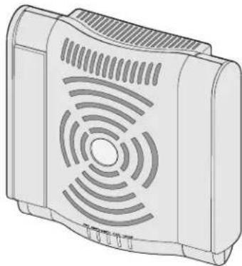
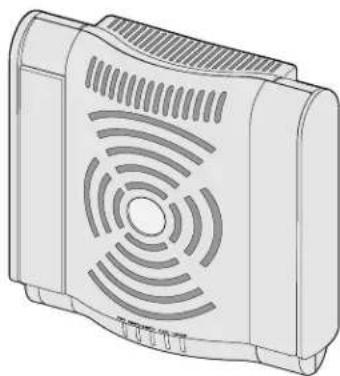
Figure 1 W-AP120 Series Access Points

natural_image
Illustration of a rectangular electronic device with ventilation grille and mounting feet (no text or symbols)W-AP120/W-AP124
(3 x RP-SMA interfaces for detachable antennas)

natural_image
Illustration of a portable electronic device with ventilation grille and control buttons (no text or symbols)W-AP121/W-AP125
(3 x integrated dual-band antennas)
Package Contents
• AP-120 series access point
• Installation guide (this document)

Note: Inform your supplier if there are any incorrect, missing, or damaged parts. If possible, retain the carton, including the original packing materials. Use these materials to repack and return the unit to the supplier if needed.

Note: Additional mounting kits for use with the W-AP120 series access points are sold separately. Contact your Dell sales representative for details.
Before You Begin
WLAN Planning
Determine how many Dell APs are needed for your wireless network deployment and where they will be installed. You can easily accomplish this planning using Dell's automated RF Plan site-survey software (available separately). This process is considered WLAN or RF planning and should have been completed during the master Dell controller installation and configuration. In typical Dell installations, the controllers are configured and installed before the APs.
For WLAN planning assistance, refer to the Indoor Access Points: Site Survey and Planning Pre-Deployment Guide and the RF Plan Installation and User Guide.
Pre-Installation Network Requirements
After WLAN planning is complete and the appropriate products and their placement have been determined, the Dell controller(s) must be installed and initial setup performed before the Dell Access Points are deployed.
For initial setup of the controller, refer to the ArubaOS Quick Start Guide for the software version installed on your controller.
Pre-Installation Checklist
Before installing your W-AP120 series access point, be sure that you have the following:
- For the W-AP120/W-AP124: External antennas as specified in the network deployment plan
• CAT5 UTP cable of required length
• One of the following power sources:
■ IEEE 802.3af-compliant Power over Ethernet (PoE) source
■ Supports full functionality for W-AP120/W-AP121; supports reduced functionality for W-AP124/W-AP125
■ IEEE Power Over Ethernet + (PoE+) source output at 56 Volts @ 350 mA
■ The POE source can be any power source equipment (PSE) controller or midspan PSE device
■ Dell AP AC-DC adapter kit (sold separately)
• Dell controller provisioned on the network:
■ Layer 2/3 network connectivity to your access point
■ One of the following network services:
• Aruba Discovery Protocol (ADP)
• DNS server with an "A" record
• DHCP Server with vendor-specific options
Summary of the Setup Process
Note: It is important that you verify the items listed under Pre-Installation Checklist before you attempt to set up and install an W-AP120 series AP.
Successful setup of an AP-120 series access point consists of five tasks, which must be performed in this order:
- Verify pre-installation connectivity.
- Identify the specific installation location for each AP.
- Install each AP.
- Verify post-installation connectivity.

5. Configure each AP.

Note: Dell, in compliance with governmental requirements, has designed the AP-120 series access points so that only authorized network administrators can change the settings. For more information about AP configuration, refer to the ArubaOS Quick Start Guide and Aruba OS User Guide.

Caution: Access points are radio transmission devices and as such are subject to governmental regulation. Network administrators responsible for the configuration and operation of access points must comply with local broadcast regulations. Specifically, access points must use channel assignments appropriate to the location in which the access point will be used.
Verifying Pre-Installation Connectivity
Before you install APs in a network environment, make sure that the APs will be able to locate and connect to the controller when powered on.
Specifically, you must verify the following conditions:
- When connected to the network, each AP is assigned a valid IP address
• APs are able to locate the controller
Refer to the ArubaOS Quick Start Guide for instructions on locating and connecting to the controller.
Identifying Specific Installation Locations
You can mount the AP-120 series access point on a wall or on the ceiling. Use the AP placement map generated by Dell's RF Plan software application to determine the proper installation location(s). Each location should be as close as possible to the center of the intended coverage area and should be free from obstructions or obvious sources of interference. These RF absorbers/reflectors/interference sources will impact RF propagation and should have been accounted for during the planning phase and adjusted for in RF plan.
Unidentified Known RF Absorbers/Reflectors/Interference Sources
Identifying known RF absorbers, reflectors, and interference sources while in the field during the installation phase is critical. Make sure that these sources are taken into consideration when you attach an AP to its fixed location.
RF absorbers include:
- Cement/concrete: Old concrete has high levels of water dissipation, which dries out the concrete, allowing for potential RF propagation. New concrete has high levels of water concentration within the concrete, blocking RF signals.
• Natural Items: Fish tanks, water fountains, ponds, and trees - Brick
RF reflectors include:
- Metal Objects: Metal pans between floors, rebar, fire doors, air conditioning/heating ducts, mesh windows, blinds, chain link fences (depending on aperture size), refrigerators, racks, shelves, and filing cabinets
- Do not place an AP between two air conditioning/heating ducts. Make sure that APs are placed below ducts to avoid RF disturbances.
RF interference sources include:
- Microwave ovens and other 2.4 or 5 GHz objects (such as cordless phones)
• Lunch rooms and call centers with cordless headsets
Installing the AP

Note: Service to all Dell products should be performed by trained service personnel only.
Using the Integrated Wall-Mounting Slots
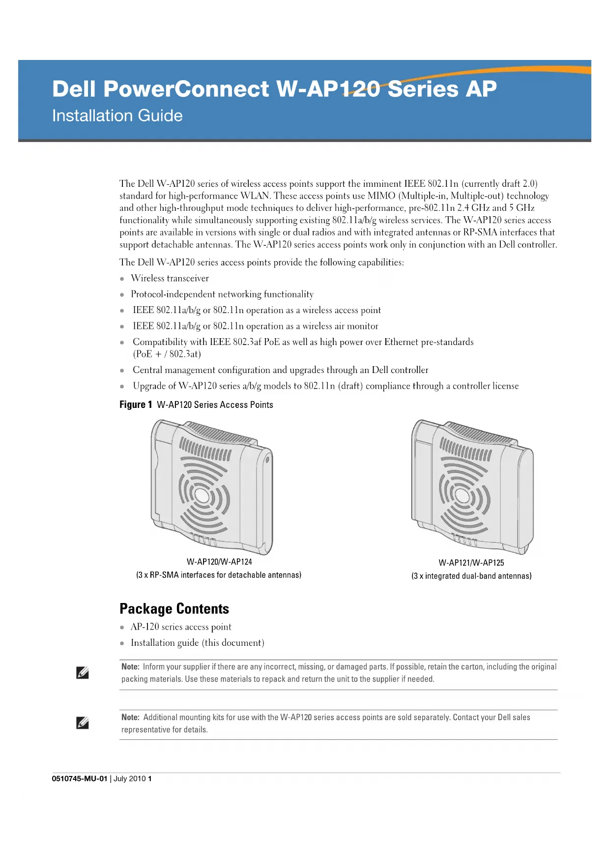
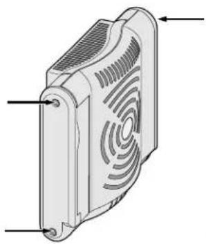
The keyhole-shaped slots on the back of the AP can be used to attach the device upright to an indoor wall or shelf. When you choose the mounting location, allow additional space at the right of the unit for cables.

Note: For product dimensions, see Product Specifications in this guide. Allow 2 inches (5 cm) of additional space at the right side of the installed unit for cables, and make sure enough space is available for antenna articulation.
- At the mounting location, install two screw on the wall or shelf, 1 7/8 inches (4.7 cm) apart. If you are attaching the device to drywall, Dell recommends using appropriate wall anchors (not included).
- Align the mounting slots on the rear of the AP over the screws and slide the unit into place (see Figure 2).
Figure 2 Installing the W-AP120 Series Access Point on a Wall
natural_image
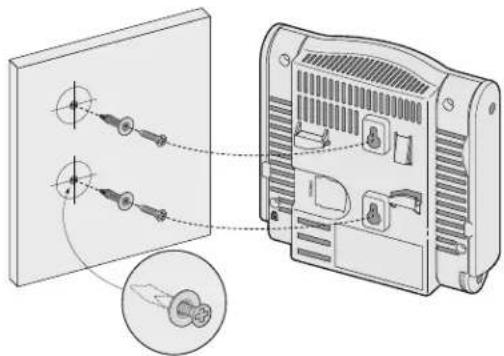
Diagram showing two components connected to a device panel, with an inset close-up of a connector detail (no text or symbols present)- On the W-AP121 or W-AP125, orient the antennas. For best performance, swivel the antennas so that they are oriented vertically, preferably in the same plane, parallel to the wall (see Figure 3).
Figure 3 Antenna Orientation on a Wall-Mounted W-AP121/W-AP125
natural_image
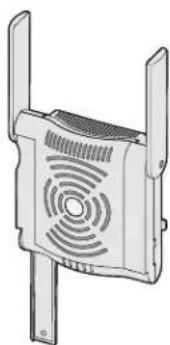
Illustration of a dual-panel electronic device with ventilation grille and two side legs (no text or symbols)On the W-AP120 or W-AP124, install the external antennas according to the manufacturer's instructions, and connect the antennas to the antenna interfaces on the AP (see Figure 4).
Figure 4 Antenna Interfaces on the W-AP120/W-AP124
natural_image
Technical illustration of a heat exchanger or fan device with ventilation grille and mounting feet (no text or symbols)Using the Integrated Ceiling Tile Rail Slots
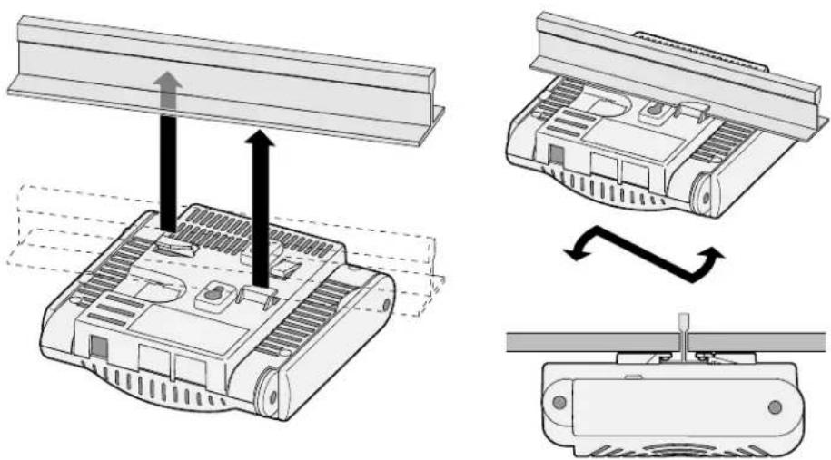
The snap-in tile rail slots on the rear of the AP can be used to securely attach the device directly to a 15/16" wide, standard ceiling tile rail.
Caution: Make sure the AP fits securely on the ceiling tile rail when hanging the device from the ceiling, because poor installation could cause it to fall onto people or equipment.
- Pull the necessary cables through a prepared hole in the ceiling tile near where the AP will be placed.
- If necessary, connect the console cable to the console port on the back of the AP.
- Hold the AP next to the ceiling tile rail with the ceiling tile rail mounting slots at approximately a 30-degree angle to the ceiling tile rail (see Figure 5). Make sure that any cable slack is above the ceiling tile.
Figure 5 Orienting the Ceiling Tile Rail Mounting Slots
natural_image
Diagram showing three views of a Raspberry Pi with heat exchangers and cooling fins, illustrating mechanical assembly (no text or symbols)- Pushing toward the ceiling tile, rotate the AP clockwise until the device clicks into place on the ceiling tile rail
- On the W-AP121 or W-AP125, orient the antennas. For best results, rotate the antennas so that they are vertical (perpendicular to the body of the AP) (see Figure 6).

Figure 6 Antenna Orientation on a Ceiling-Mounted W-AP121/W-AP125

natural_image
Line drawing of a four-legged electronic device with a ventilation grille (no text or symbols)On the W-AP120 or W-AP124, install the external antennas according to the manufacturer's instructions, and connect the antennas to the antenna interfaces on the AP (see Figure 4).
Connecting Required Cables
Install cables in accordance with all applicable local and national regulations and practices.
Ethernet Ports
The RJ45 Ethernet ports (ENET0 and ENET1) support 100/1000Base-T auto-sensing MDI/MDX connections. Use these ports to connect the AP to a twisted pair Ethernet LAN segment or directly to an Dell controller. Use a 4- or 8-conductor, Category 5 UTP cable up to 100 m (325 feet) long.
Note: Dell W-AP120 series APs are intended only for installation in Environment A as defined in IEEE 802.3.af, Power over Ethernet. All interconnected equipment must be contained within the same building, including the interconnected equipment's associated LAN connections.
The 100/1000 Mbps Ethernet ports are on the bottom of the AP. These ports have RJ-45 female connectors with the pin-outs shown in Table 1.
Table 1 Connector for Ethernet Ports ENET0 and ENET1
| Connector Pin | Signal Name | GE Connection | FE Connection | PoE |
 | 1 BI_DA+ Bi-directional pair A+ RX+ POE negative | |||
| 2 BI_DA- Bi-directional pair A- RX- POE negative | ||||
| 3 BI_DB+ Bi-directional pair B+ TX+ POE positive | ||||
| 4 BI_DC+ Bi-directional pair C+ Spare pair POE positive | ||||
| 5 BI_DC- Bi-directional pair C- Spare pair POE positive | ||||
| 6 BI_DB- Bi-directional pair B- TX- POE positive | ||||
| 7 BI_DD+ Bi-directional pair D+ Spare pair POE negative | ||||
| 8 BI_DB- Bi-directional pair D- Spare pair POE negative | ||||

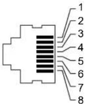
Serial Console Port
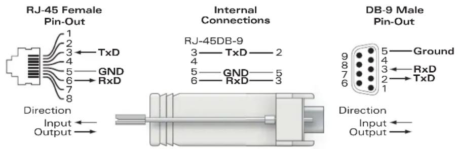
The serial console port allows you to connect the AP to a serial terminal or a laptop for direct local management. This port is an RJ-45 female connector with the pinouts described in Table 2. Connect this port in one of the following ways:
- Connect it directly to a terminal or terminal server using an Ethernet cable.
- Use a modular adapter to convert the RJ-45 (female) connector on the AP to a DB-9 (male) connector, and connect the adapter to a laptop using an RS-232 cable. See Figure 7 for connector details of the adapter.
Table 2 Connector for Serial Console Port
Connector Pin Signal Name Function
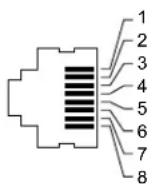
3
TXD
Transmit
4 GND Ground
5 GND Ground
6 RXD Receive
Pins not listed are not connected.
Figure 7 RJ-45 (Female) to DB-9 (Male) Modular Adapter Conversion
Power Connection
The W-AP120 series AP has a single 5V DC power jack socket to support powering through an AC-to-DC mains electric power adapter.
Note: If both POE and DC power are available, the AP uses POE, even when there is not enough POE voltage available to power the AP.
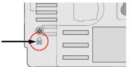
Connecting a Security Cable
To provide added security for the W-AP121 or W-AP125, you can attach a security cable to the back of the unit (see Figure 8).
Figure 8 Security Lock Connection
Verifying Post-Installation Connectivity
The integrated LEDs on the AP can be used at this point to verify that the AP is receiving power and initializing successfully (see Table 3). Refer to the ArubaOS Quick Start Guide for further details on verifying post-installation network connectivity.
| LED Color/State Meaning | ||
| PWR Green steady Power on, device ready | ||
| Green flashing System initializing | ||
| Red steady System failed to initialize, contact TAC | ||
| ENET 0(100/1000 Mbps) | Green/Amber off No link | |
| Green on 1000 Mbps link | ||
| Amber on 100 Mbps link | ||
| Green/amber blinking Data activity | ||
| ENET 1(100/1000 Mbps) | Green/Amber off No Link | |
| Green on 1000 Mbps link | ||
| Amber on 100 Mbps link | ||
| Green/amber blinking Data activity | ||
| 11A/N Amber Wireless link is legacy 11a | ||
| Green | Wireless link is 11n 5 Ghz band | |
| 11B/G/N | Amber Wireless link is legacy | 11b or 11g |
| Green | Wireless link is 11n 2.4 Ghz band | |
Configuring the W-AP120 Series
AP Provisioning/Reprovisioning
Provisioning parameters are unique to each AP. These local AP parameters are initially configured on the controller which are then pushed out to the AP and stored on the AP itself. Dell recommends that provisioning settings be configured via the ArubaOS Web UI only. Refer to the ArubaOS User Guide for complete details.
AP Configuration
Configuration parameters are network or controller specific and are configured and stored on the controller. Network configuration settings are pushed out to the AP(s) but remain stored on the controller.
Configuration settings can be configured via the ArubaOS Web UI, ArubaOS CLI, or Aruba MMS. Refer to their respective guides for further details: the ArubaOS User Guide.
Product Specifications
Mechanical
• Dimensions (antenna stowed) (HxWxD):
■ 4.9 inches x 5.13 inches x 2 inches
■ 12.4 cm x 13 cm x 5.1 cm
• Weight: 15 oz/0.42 kg
• Shipping Dimensions:
■ 9.5 inches x 7.25 inches x 4.5 inches
■ 24.1 cm x 18.4 cm x 11.4 cm
• Temperature:
■ Operating: 0^ C to 50^ C ( 32^ F to 122^ F)
■ Storage: -10^ to 70^ ( 14^ to 158^ )
Note: During normal operation, the temperature of the base of the W-AP120 series can approach 80^ C ( 176^ F). This is within the expected operating temperature range.
• Relative Humidity: 5% to 95% non-condensing
• Altitude: 8,000 ft @ 28°C (82.4°F)
- Mounting: Wall, ceiling, or desktop mountable
- Antennas:
■ 3 integrated articulating dual-band antenna elements (W-AP121, W-AP125)
■ 3 RP-SMA interfaces for external antennas (W-AP120, W-AP124)
• Visual Status Indicators (LEDs): See Table 3
Electrical
Ethernet:
■ 2 x 100/1000 Base-T auto-sensing Ethernet RJ-45 Interfaces
MDI/MDX
■ IEEE 802.3 (10Base-T), IEEE 802.3u (100Base-T). IEEE 802.3ab (1000Base-T)
■ Power over Ethernet (IEEE 802.3af compliant), 48V DC/350mA (see Table 1 for pin configuration)
• Power:
■ 5 VDC power interface, supports powering through an AC-to-DC mains electric power adapter

Note: If a power adapter other than the one provided by Dell is used in the US or Canada, it should be cULus (NRTL) Listed, with an output rated 5 VDC, minimum 4A, marked "LPS" or "Class 2," and suitable for plugging into a standard power receptacle in the US and Canada.

■ POE support on Ethernet ports:
- 802.3af-compliant POE sourcing devices
- POE+ (56 V @ 350 mA)
Wireless LAN
• Network Standards: IEEE 802.11b, IEEE 802.11g, IEEE 802.11a, and IEEE 802.11n (draft)
- Antenna Type:
■ Integrated 802.11a/b/g/n omni-directional high-gain antenna
■ Detachable 802.11a/b/g/n omni-directional high-gain antenna
• Antenna Gain (Integrated Antennas):
■ 2.4 - 2.5 GHz/3.2 dBi (max)
■ 5.180 - 5.825 GHz/5.2 dBi (max)
- Radio Technology:
■ Orthogonal Frequency Division Multiplexing (OFDM)
■ Direct Sequence Spread Spectrum (DSSS)
• Radio Modulation Type:
■ 802.11b - CCK, BPSK, QPSK
■ 802.11g - CCK, BPSK, QPSK, 16-QAM, 64-QAM
■ 802.11a - BPSK, QPSK, 16-QAM, 64-QAM
■ 802.11n draft 2.0
• Media Access Control: CSMA/CA with ACK
• Supported Frequency Bands 2.4GHz:
■ 2.400 \~ 2.4835GHz (Global), channels country specific
• Supported Frequency Bands 5GHz:
■ 5.150 \~ 5.250GHz (low band), country-specific
■ 5.250 \~ 5.350GHz (mid band), country-specific
■ 5.470 \~ 5.725GHz (Europe), country-specific
5.725 \~ 5.825GHz GHz (high band), country-specific
| 802.11b 802.11g 802.11a 802.11n | |||
| US, Canada 11 US, Canada | da 11 US, Canada 12 << NEED >> | ||
| ETSI 13 ETSI 13 ETSI (up to 19) << NEED >> | |||
| Japan 14 Japan 13 Japan | 4 << NEED >> | ||
| Taiwan 11 Taiwan 11 Taiwan | 7 << NEED >> | ||
• Data Rates:
■ 802.11b - 1, 2, 5.5, 11 Mbps per channel
■ 802.11g - 6, 9, 12, 18, 24, 36, 48 and 54 Mbps per channel
■ 802.11a - 6, 9, 12, 18, 24, 36, 48 and 54 Mbps per channel
■ 802.11n - Data rate MCS0 - MCS15 (from 6.5 Mbps to 300 Mbps)
Proper Disposal of Dell Equipment
For the most current information on Global Environmental Compliance and Dell products please refer to the Dell PowerConnect W-Series Safety, Environmental, and Regulatory Information document is included with this product or see our website at www.dell.com.
European Union RoHS
RoHS
Aruba products also comply with the EU Restriction of Hazardous Substances Directive 2002/95/E.C (RoIIS). EU RoIIS restricts the use of specific hazardous materials in the manufacture of electrical and electronic equipment. Specifically, restricted materials under the RoHS Directive are Lead (including Solder used in printed circuit assemblies), Cadmium, Mercury, Hexavalent Chromium, and Bromine. Some Aruba products are subject to the exemptions listed in RoHS Directive Annex 7 (Lead in solder used in printed circuit assemblies). Products and packaging will be marked with the "RoHS" label shown at the left indicating conformance to this Directive.
Battery Replacement

Caution: Batteries included with Dell products must be replaced by qualified Dell service personnel only. Contact Dell for battery replacement. Do not attempt to replace the battery. There is a risk of explosion if you install the wrong type of battery. Dispose of batteries according to the instructions.
Safety and Regulatory Compliance
Dell provides a multi-language document containing country specific restrictions and additional safety and regulatory information for all Dell hardware products. The Dell PowerConnect W-Series Safety, Environmental, and Regulatory Information document is included with this product.

Caution: RF Radiation Exposure Statement: This equipment complies with FCC RF radiation exposure limits. This equipment should be installed and operated with a minimum distance of 13.78 inches (35 cm) between the radiator and your body for 2.4 GHz and 5 GHz operations. This transmitter must not be co-located or operating in conjunction with any other antenna or transmitter. When operated in the 5.15 to 5.25 GHz frequency range, this device is restricted to indoor use to reduce the potential for harmful interference with co-channel Mobile Satellite Systems.
Korean Radio Equipment Warning Notice
Radio Equipment for the radio data communication system
** Warning Notice **
For a radio equipment using 2400\~2483.5MHz or 5725\~5825MHz, the following two expression should be displayed;
- Indicate following expression on the product where is easy to see: "This radio equipment can be crossed during operation."
- The manufacturer and installer should fully inform the operator or users "This radio equipment cannot provide a service relevant to the human life safety, as it can be crossed" through the user manual etc.
© 2010 Aruba Networks, Inc. AirWave®, Aruba Networks®, Aruba Mobility Management System®, Bluescanner, For Wireless That Works®, Mobile Edge Architecture®, People Move. Networks Must Follow®, RFprotect®, The All Wireless Workplace Is Now Open For Business, Green Island, and The Mobile Edge Company® and other registered marks are trademarks of Aruba Networks, Inc. Dell™, the DELL™ logo, and PowerConnect™ are trademarks of Dell Inc.
All rights reserved. Specifications in this manual are subject to change without notice.
Originated in the USA. Any other trademarks appearing in this manual are the property of their respective companies.
Open Source Code
Certain Aruba products include Open Source software code developed by third parties, including software code subject to the GNU General Public License (GPL), GNU Lesser General Public License (LGPL), or other Open Source Licenses. The Open Source code used can be found at this site:
http://www.arubanetworks.com/open_source
Legal Notice
The use of Aruba Networks, Inc. switching platforms and software, by all individuals or corporations, to terminate other vendors' VPN client devices constitutes complete acceptance of liability by that individual or corporation for this action and indemnifies, in full, Aruba Networks, Inc. from any and all legal actions that might be taken against it with respect to infringement of copyright on behalf of those vendors.
Warranty
This hardware product is protected by the standard Aruba warranty of one year parts/labor. For more information, refer to the ARUBACARE SERVICE AND SUPPORT TERMS AND CONDITIONS.
Altering this device (such as painting it) voids the warranty.

Dell PowerConnect W-AP120 Serie AP
natural_image
Illustration of a rectangular electronic device with ventilation grille and mounting feet (no text or symbols)natural_image
Illustration of a portable electronic device with ventilation grille and ports (no text or symbols)natural_image
Diagram showing cable connection to a device panel with an inset close-up of its cable (no text or symbols present)natural_image
Illustration of a dual-panel electronic device with ventilation grille and two leads (no text or symbols)natural_image
Technical illustration of a rectangular electronic device with ventilation grilles and mounting holes (no text or symbols)natural_image
Diagram showing three stages of a device assembly: top view, side view with arrows indicating motion, and bottom view with a screw (no text or symbols)natural_image
Technical line drawing of a four-legged electronic component with a ventilation grille (no text or symbols)
■ Orthogonal Frequency Division Multiplexing (OFDM)
■ Direct Sequence Spread Spectrum (DSSS)
Radio Equipment for the radio data communication system
** Warning Notice **
For a radio equipment using 2400\~2483.5MHz or 5725\~5825MHz, the following two expression should be displayed;
- Indicate following expression on the product where is easy to see: "This radio equipment can be crossed during operation."
- The manufacturer and installer should fully inform the operator or users "This radio equipment cannot provide a service relevant to the human life safety, as it can be crossed" through the user manual etc.
natural_image
Illustration of a rectangular electronic device with a circular ventilation grille (no text or symbols)natural_image
Illustration of a rectangular electronic device with ventilation grille and ports (no text or symbols)natural_image
Diagram showing two electronic devices connected to a panel, with one device highlighted and the other showing internal components (no text or symbols present)natural_image
Illustration of a dual-panel electronic device with ventilation grille and two leads (no text or symbols)natural_image
Technical illustration of a rectangular electronic device with ventilation grilles and mounting holes (no text or symbols)natural_image
Diagram showing three stages of a device assembly: top view, side view with arrows indicating motion, and bottom view with a switch (no text or symbols present)natural_image
Technical line drawing of a four-legged electronic device with a ventilation grille (no text or symbols)Radio Equipment for the radio data communication system
** Warning Notice **
For a radio equipment using 2400\~2483.5MHz or 5725\~5825MHz, the following two expression should be displayed;
- Indicate following expression on the product where is easy to see: "This radio equipment can be crossed during operation."
- The manufacturer and installer should fully inform the operator or users "This radio equipment cannot provide a service relevant to the human life safety, as it can be crossed" through the user manual etc.
natural_image
Illustration of a rectangular electronic device with ventilation grille and mounting feet (no text or symbols)W-AP120/W-AP124
(3 interfaces RP-SMA para antenas extraíbles)

natural_image
Illustration of a portable electronic device with ventilation grille and ports (no text or symbols)natural_image
Diagram showing two electronic devices connected to a panel, with one device highlighted and the other showing internal components (no text or symbols present)natural_image
Illustration of a dual-panel electronic device with ventilation grille and two leads (no text or symbols)natural_image
Technical illustration of a mechanical component with ventilation slots and mounting holes (no text or symbols)natural_image
Diagram showing three stages of a device assembly: top view, side view with arrows indicating motion, and bottom view with a switch (no text or symbols present)natural_image
Technical line drawing of a four-legged electronic device with a speaker grille (no text or symbols)Radio Equipment for the radio data communication system
\*\* Warning Notice \*\*
For a radio equipment using 2400\~2483.5MHz or 5725\~5825MHz, the following two expression should be displayed;
- Indicate following expression on the product where is easy to see: "This radio equipment can be crossed during operation."
- The manufacturer and installer should fully inform the operator or users "This radio equipment cannot provide a service relevant to the human life safety, as it can be crossed" through the user manual etc.
natural_image
Illustration of a rectangular electronic device with ventilation grille and mounting feet (no text or symbols)natural_image
Illustration of a portable electronic device with ventilation grille and ports (no text or symbols)W-AP121/W-AP125
(3 antenas de banda dual integradas)
natural_image
Diagram showing two electronic devices connected to a panel, with an inset close-up of the device's cable (no text or symbols present)natural_image
Illustration of a dual-panel electronic device with ventilation grille and two leads (no text or symbols)natural_image
Diagram of a rectangular electronic device with ventilation grille and mounting feet (no text or symbols)natural_image
Technical illustration of a device with three views showing internal components and directional arrows (no text or symbols)natural_image
Line drawing of a four-legged electronic device with a ventilation grille (no text or symbols)Radio Equipment for the radio data communication system
** Warning Notice **
For a radio equipment using 2400\~2483.5MHz or 5725\~5825MHz, the following two expression should be displayed;
- Indicate following expression on the product where is easy to see: "This radio equipment can be crossed during operation."
- The manufacturer and installer should fully inform the operator or users "This radio equipment cannot provide a service relevant to the human life safety, as it can be crossed" through the user manual etc.
© 2010 Aruba Networks, Inc. AirWave®, Aruba Networks®, Aruba Mobility Management System®, Bluescanner, For Wireless That Works®, Mobile Edge Architecture®, People Move. Networks Must Follow®, RFprotect®, The All Wireless Workplace Is Now Open For Business, Green Island, The Mobile Edge Company® e outras marcas registradas são marcas comerciais da Aruba Networks, Inc. Dell™, o logotipo DELL™ e PowerConnect™ são marcas comerciais da Dell Inc.
natural_image
Illustration of a rectangular electronic device with ventilation grille and mounting feet (no text or symbols)natural_image
Illustration of a portable electronic device with ventilation grille and control buttons (no text or symbols)W-AP121/W-AP125
(3 x entegre çift bant antenler)
Ambalaj İçeriği
natural_image
Diagram showing cable connector assembly from a panel to an electronic device, with magnified detail of the component (no text or symbols present)natural_image
Illustration of a dual-chamber WiFi router with ventilation grille (no text or symbols)natural_image
Technical line drawing of a heat exchanger or fan device with ventilation grille and mounting feet (no text or symbols)natural_image
Diagram showing three stages of a device assembly: top view, side view with arrows indicating motion, and bottom view with a sensor or sensor component (no text or symbols present)natural_image
Line drawing of a mechanical component with a fan-like structure and ventilation grille (no text or symbols)Radio Equipment for the radio data communication system
\*\* Warning Notice \*\*
For a radio equipment using 2400\~2483.5MHz or 5725\~5825MHz, the following two expression should be displayed;
- Indicate following expression on the product where is easy to see: "This radio equipment can be crossed during operation."
- The manufacturer and installer should fully inform the operator or users "This radio equipment cannot provide a service relevant to the human life safety, as it can be crossed" through the user manual etc.
© 2010 Aruba Networks, Inc. AirWave®, Aruba Networks®, Aruba Mobility Management System®, Bluescanner, For Wireless That Works®, Mobile Edge Architecture®, People Move. Networks Must Follow®, RFprotect®, The All Wireless Workplace Is Now Open For Business, Green Island, and The Mobile Edge Company® ve diğer tescilli markalar, Aruba Networks, Inc.'nin ticari markalarıdır. Dell™, DELL™ logosu ve PowerConnect™, Dell Inc.'nin ticari markalarıdır.
natural_image
Illustration of a rectangular electronic device with ventilation grille and mounting feet (no text or symbols)natural_image
Illustration of a portable electronic device with ventilation grille and ports (no text or symbols)natural_image
Diagram showing two electronic devices connected to a panel, with one device highlighted and the other inside (no text or symbols present)natural_image
Illustration of a dual-chamber WiFi router with ventilation grille (no text or symbols)natural_image
Technical illustration of a rectangular electronic device with ventilation grilles and mounting holes (no text or symbols)一体型天井タイルレールスロットの使用
natural_image
Technical illustration of a mechanical device with three views showing assembly and rotation (no text or symbols)natural_image
Technical line drawing of a spider-like device with ventilation grille and legs (no text or symbols)設置後の接続の確認
Radio Equipment for the radio data communication system
** Warning Notice **
For a radio equipment using 2400\~2483.5MHz or 5725\~5825MHz, the following two expression should be displayed;
- Indicate following expression on the product where is easy to see: "This radio equipment can be crossed during operation."
- The manufacturer and installer should fully inform the operator or users "This radio equipment cannot provide a service relevant to the human life safety, as it can be crossed" through the user manual etc.
natural_image
Illustration of a rectangular electronic device with ventilation grille and mounting feet (no text or symbols)natural_image
Illustration of a portable electronic device with ventilation grille and ventilation slots (no text or symbols)WLAN 설계를 위해 Indoor Access Points: Site Survey and Planning Pre-Deployment Guide와 RF Plan Installation and User Guide를 참조하십시오.
설치 전 네트워크 요구 사항
natural_image
Diagram showing cable connection to a device panel with an inset close-up of its cable (no text or symbols present)natural_image
Illustration of a white electronic device with ventilation grille and two side connectors (no text or symbols)natural_image
Technical illustration of a heat exchanger or fan device with ventilation grille and mounting base (no text or symbols)천장 타일 내장 레일 슬롯 사용
natural_image
Diagram showing three views of a device with arrows indicating assembly or movement, no text or symbols present.natural_image
Line drawing of a small electronic device with a fan and ventilation grille (no text or symbols)설치 후 연결 확인
Radio Equipment for the radio data communication system
** Warning Notice **
For a radio equipment using 2400\~2483.5MHz or 5725\~5825MHz, the following two expression should be displayed;
- Indicate following expression on the product where is easy to see: "This radio equipment can be crossed during operation."
- The manufacturer and installer should fully inform the operator or users "This radio equipment cannot provide a service relevant to the human life safety, as it can be crossed" through the user manual etc.
natural_image
Illustration of a rectangular electronic device with ventilation grille and mounting feet (no text or symbols)W-AP120/W-AP124
(3個用於可拆卸式天線的RP-SMA介面)
natural_image
Illustration of a portable electronic device with ventilation grille and ports (no text or symbols)W-AP121/W-AP125
(3個整合式雙頻天線)
包裝內容
natural_image
Diagram showing two electronic devices connected to a panel, with an inset close-up of the device's cable (no text or symbols present)natural_image
Illustration of a dual-panel electronic device with ventilation grille and antenna (no text or symbols)natural_image
Technical illustration of a heat exchanger or fan device with ventilation grille and mounting base (no text or symbols)使用整合的吊頂板軌道槽
natural_image
Diagram showing three views of a device with arrows indicating assembly or movement, no text or symbols present.natural_image
Line drawing of a small electronic device with a fan and ventilation grille (no text or symbols)確認安裝後的連通性
Radio Equipment for the radio data communication system
** Warning Notice **
For a radio equipment using 2400\~2483.5MHz or 5725\~5825MHz, the following two expression should be displayed;
- Indicate following expression on the product where is easy to see: "This radio equipment can be crossed during operation."
- The manufacturer and installer should fully inform the operator or users "This radio equipment cannot provide a service relevant to the human life safety, as it can be crossed" through the user manual etc.
natural_image
Illustration of a rectangular electronic device with ventilation grille and mounting feet (no text or symbols)W-AP120/W-AP124
(3个用于可拆卸式天线的RP-SMA接口)
natural_image
Illustration of a portable electronic device with ventilation grille and buttons (no text or symbols)W-AP121/W-AP125
(3个集成式双频天线)
包装内容
natural_image
Diagram showing cable connection to a device panel with an inset close-up of its cable (no text or symbols present)natural_image
Illustration of a dual-panel electronic device with ventilation grille and antenna (no text or symbols)natural_image
Technical illustration of a heat exchanger or fan device with ventilation grille and mounting base (no text or symbols)使用集成的吊顶板轨道槽
natural_image
Diagram showing three views of a device with arrows indicating assembly or transformation (no text or symbols present)natural_image
Line drawing of a small electronic device with a fan and ventilation grille (no text or symbols)确认安装后的连通性
Radio Equipment for the radio data communication system
** Warning Notice **
For a radio equipment using 2400\~2483.5MHz or 5725\~5825MHz, the following two expression should be displayed;
- Indicate following expression on the product where is easy to see: "This radio equipment can be crossed during operation."
- The manufacturer and installer should fully inform the operator or users "This radio equipment cannot provide a service relevant to the human life safety, as it can be crossed" through the user manual etc.
natural_image
Illustration of a rectangular electronic device casing with ventilation grille and mounting feet (no text or symbols)natural_image
Illustration of a portable electronic device with ventilation grille and ventilation slots (no text or symbols)W-AP121/W-AP125
(3 x antena dual-band terintegrasi)
Isi Kemasan
natural_image
Diagram showing two electronic devices connected to a panel, with one device highlighted and the other inside (no text or symbols present)natural_image
Illustration of a dual-panel electronic device with ventilation grille and two leads (no text or symbols)natural_image
Technical illustration of a rectangular electronic device with ventilation grilles and mounting holes (no text or symbols)natural_image
Technical illustration of a device with three views showing internal components and directional arrows (no text or symbols)natural_image
Line drawing of a four-legged plastic stand with a perforated cover and ventilation grille (no text or symbols)■ Antena omni high-gain 802.11a/b/g/n terintegrasi
■ Antena omni high-gain 802.11a/b/g/n yang dapat dilepas
• Gain Antena (Antena Terintegrasi):
■ 2,4-2,5 GHz/3,2 dBi (maks)
■ 5,180 - 5,825 GHz/5,2 dBi (maks)
- Teknologi Radio:
Radio Equipment for the radio data communication system
** Warning Notice **
For a radio equipment using 2400\~2483.5MHz or 5725\~5825MHz, the following two expression should be displayed;
- Indicate following expression on the product where is easy to see: "This radio equipment can be crossed during operation."
- The manufacturer and installer should fully inform the operator or users "This radio equipment cannot provide a service relevant to the human life safety, as it can be crossed" through the user manual etc.
• air monitor -© IEEE 802.11a/b/g or 802.11n
high power over Ethernet 750-123-0000 IEEE 802.3af PoE 750-123-0000
(PoE + / 802.3at)
natural_image
Illustration of a rectangular electronic device with ventilation slots and a circular top (no text or symbols)natural_image
Illustration of a portable electronic device with ventilation grille and ventilation slots (no text or symbols)W-AP121/W-AP125
(הכלההₓ 3)
תְרָה בְּרָה
Indoor Access Points: Site Survey and Planning Pre-Deployment :WLAN WILK. RF Plan Installation and User Guide - Guide
Dell 17/17/17, 02:17:17, 03:17:17, 04:17:17, 05:17:17, 06:17:17, 07:17:17, 08:17:17, 09:17:17, 10:17:17, 11:17:17, 12:17:17, 13:17:17, 14:17:17, 15:17:17, 16:17:17, 17:17:17, 18:17:17, 19:17:17, 20:17:17, 21:17:17, 22:17:17, 23:17:17, 24:17:17, 25:17:17, 26:17:17, 27:17:17, 28:17:17, 29:17:17, 30:17:17, 31:17:17, 32:17:17, 33:17:17, 34:17:17, 35:17:17, 36:17:17, 37:17:17, 38:17:17, 39:17:17, 40:17:17, 41:17:17, 42:17:17, 43:17:17, 44:17:17, 45:17:17, 46:17:17, 47:17:17, 48:17:17, 49:17:17, 50:17:17, 51:17:17, 52:17:17, 53:17:17, 54:17:17, 55:17:17, 56:17:17, 57:17:17, 58:17:17, 59:17:17, 60:17:17, 61:17:17, 62:17:17, 63:17:17, 64:17:17, 65:17:17, 66:17:17, 67:17:17, 68:17:17, 69:17:17, 70:17:17, 71:17:17, 72:17:17, 73:17:17, 74:17:17, 75:17:17, 76:17:17, 77:17:17, 78:17:17, 79:17:17, 80:17:17, 81.
(הכלהה) AP AC-DC Dell
natural_image
Diagram showing cable connection to a device panel with an inset close-up of its connector (no text or symbols present)natural_image
Illustration of a dual-chamber wireless router with ventilation grille (no text or symbols)natural_image
Technical illustration of a heat exchanger or fan device with ventilation grilles and mounting holes (no text or symbols)natural_image
Diagram of a robotic device with two upward arrows indicating motion or force, mounted on a flat panel (no text or symbols present)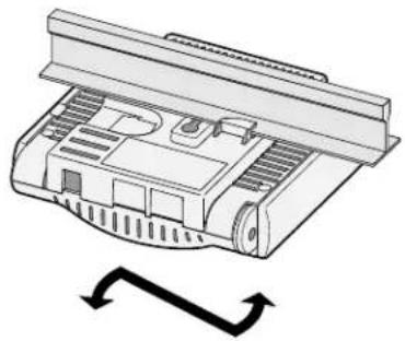
natural_image
Diagram of a mechanical component with a curved arrow indicating rotation or movement (no text or symbols present)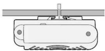
natural_image
Pure technical diagram of a mechanical component with no text, numbers, or symbolsnatural_image
Technical line drawing of a four-legged electronic component with a ventilation grille (no text or symbols)ENET1 - ENET0 is any Ethernet is any
תְבָרִיֹן
1BI_DA+ Bi-directional pair A+RX+POE negative

POE positive
POE positive
Spare pair Bi-directional pair C+ BI_DC+
p5Be_pdr-Bi-directional pair C-
POE positive
6BI_DB—Bi-directional pair B—
POE positive
Spare pairPBEdiregditional pair D+ 7BI_DD+
SpBe_DB-PBiEdiregtridial pair D-
תְרָה בְּרָה בְּרָה
.הכלההוּרָהוּרָהוּרָהוּרָהוּרָהוּרָהוּרָהוּרָהוּרָהוּרָהוּרָהוּרָהוּרָהוּרָהוּרָה

,,cULus (NRTL) Listed "Dell" is "Class 2" is "LPS" is "Class 3", "Class 4" is "Class 5", "Class 6" is "Class 7", and "Class 8" is "Class 9" is "Class 10".
802.3af-compliant POE sourcing devices –
POE+ (56 V @ 350 mA) -
'vinn' LAN
Network Standards: IEEE 802.11b, IEEE 802.11g, IEEE 802.11a, and IEEE 802.11n (draft)
אַרְשָׁה
הכלהה 802.11a/b/g/n
Orthogonal Frequency Division Multiplexing (OFDM)
Direct Sequence Spread Spectrum (DSSS)
• Among
802.11b - CCK, BPSK, QPSK
802.11g - CCK, BPSK, QPSK, 16-QAM, 64-QAM
802.11a - BPSK, QPSK, 16-QAM, 64-QAM
802.11n draft 2.0
הַרְׁבָּל 802.11g - 6, 9, 12, 18, 24, 36, 48 and 54 Mbps
הכלה 802.11a - 6, 9, 12, 18, 24, 36, 48 and 54 Mbps
(Mbps 300 τν Mbps 6.5 -n) 802.11n - Data rate MCS0 – MCS15
Dell PowerConnect W-Series, Dell PowerConnect W-Series, Dell PowerConnect W-Series, Dell PowerConnect W-Series, Dell PowerConnect W-Series, Dell PowerConnect W-Series, Dell PowerConnect W-Series, Dell PowerConnect W-Series, Dell PowerConnect W-Series, Dell PowerConnect W-Series, Dell PowerConnect W-Series, Dell PowerConnect W-Series, Dell PowerConnect W-Series, Dell PowerConnect W-Series, Dell PowerConnect W-Series, Dell PowerConnect W-Series, Dell PowerConnect W-Series, Dell PowerConnect W-Safety, Environmental, and Regulatory Information
.www.dell.com
Radio Equipment for the radio data communication system
** Warning Notice **
For a radio equipment using 2400\~2483.5MHz or 5725\~5825MHz, the following two expression should be displayed;
- Indicate following expression on the product where is easy to see: "This radio equipment can be crossed during operation."
- The manufacturer and installer should fully inform the operator or users "This radio equipment cannot provide a service relevant to the human life safety, as it can be crossed" through the user manual etc.
.SUPPORT TERMS AND CONDITIONS


- Dell PowerConnect W-AP120 Series AP Installation Guide
- Package Contents
- Before You Begin
- WLAN Planning
- Pre-Installation Network Requirements
- Pre-Installation Checklist
- Summary of the Setup Process
- Configure each AP.
- Verifying Pre-Installation Connectivity
- Identifying Specific Installation Locations
- Unidentified Known RF Absorbers/Reflectors/Interference Sources
- Installing the AP
- Using the Integrated Wall-Mounting Slots
- Using the Integrated Ceiling Tile Rail Slots
- Connecting Required Cables
- Ethernet Ports
- Serial Console Port
- Power Connection
- Connecting a Security Cable
- Verifying Post-Installation Connectivity
- Configuring the W-AP120 Series
- AP Provisioning/Reprovisioning
- AP Configuration
- Product Specifications
- Mechanical
- Electrical
- Wireless LAN
- Proper Disposal of Dell Equipment
- European Union RoHS
- RoHS
- Battery Replacement
- Safety and Regulatory Compliance
- Korean Radio Equipment Warning Notice
- Open Source Code
- Legal Notice
- Warranty
- Dell PowerConnect W-AP120 Serie AP
- \*\* Warning Notice \*\*
- Ambalaj İçeriği
- 一体型天井タイルレールスロットの使用
- 設置後の接続の確認
- 설치 전 네트워크 요구 사항
- 천장 타일 내장 레일 슬롯 사용
- 설치 후 연결 확인
- 包裝內容
- 使用整合的吊頂板軌道槽
- 確認安裝後的連通性
- 包装内容
- 使用集成的吊顶板轨道槽
- 确认安装后的连通性
- Isi Kemasan
- תְרָה בְּרָה
- תְרָה בְּרָה בְּרָה
- 'vinn' LAN
Brand : DELL
Model : WAP124125
Category : Access Point