
PowerConnect W-AP92 - Access Point DELL - Free user manual and instructions
Find the device manual for free PowerConnect W-AP92 DELL in PDF.


| Product Type | Wireless Access Point |
| Model | PowerConnect W-AP92 |
| Wireless Standards | IEEE 802.11a/b/g/n/ac |
| Frequency Bands | 2.4 GHz and 5 GHz |
| Maximum Data Rate | 867 Mbps (5 GHz) + 300 Mbps (2.4 GHz) |
| Antenna Type | Internal dual-band antennas |
| Interfaces | 1 x Gigabit Ethernet (PoE), 1 x Console (RJ-45) |
| Power Method | Power over Ethernet (802.3af) or 12V DC adapter |
| Power Consumption | 12.95 W (typical) |
| Dimensions (W x D x H) | 20.5 x 20.5 x 4.5 cm (8.1 x 8.1 x 1.8 in) |
| Weight | 0.6 kg (1.32 lbs) |
| Mounting | Ceiling or wall mount (bracket included) |
| Security | WPA/WPA2/WPA3, 802.1X, MAC filtering, rogue AP detection |
| Management | Web GUI (HTTP/HTTPS), SNMP, CLI (SSH), Dell NMS support |
| Operating Temperature | 0°C to 50°C (32°F to 122°F) |
| Humidity | 5% to 95% (non-condensing) |
| LED Indicators | Power, Ethernet, Wireless (2.4G/5G) |
| Certifications | FCC, CE, IC, UL, Wi-Fi Alliance |
| Included Accessories | Mounting bracket, screws, quick start guide, CD |
| Warranty | Limited Lifetime Warranty |
Frequently Asked Questions - PowerConnect W-AP92 DELL
User questions about PowerConnect W-AP92 DELL
0 question about this device. Answer the ones you know or ask your own.
Ask a new question about this device
Download the instructions for your Access Point in PDF format for free! Find your manual PowerConnect W-AP92 - DELL and take your electronic device back in hand. On this page are published all the documents necessary for the use of your device. PowerConnect W-AP92 by DELL.
USER MANUAL PowerConnect W-AP92 DELL
FIPS 140-2 Non-Proprietary Security Policy for Aruba AP-92, AP-93, AP-105, AP-175 Dell W-AP92, W-AP93, W-AP105 and W-AP175 Wireless Access Points
Version 1.2
Feb. 2012

networks
Aruba Networks™
1322 Crossman Ave.
Sunnyvale, CA 94089-1113

Copyright
© 2012 Aruba Networks, Inc. Aruba Networks trademarks include Airwave, Aruba Networks®, Aruba Wireless Networks®, the registered Aruba the Mobile Edge Company logo, Aruba Mobility Management System®, Mobile Edge Architecture®, People Move. Networks Must Follow®, RFProtect®, Green Island®. All rights reserved. All other trademarks are the property of their respective owners. Open Source Code
Certain Aruba products include Open Source software code developed by third parties, including software code subject to the GNU General Public License (GPL), GNU Lesser General Public License (LGPL), or other Open Source Licenses. The Open Source code used can be found at this site:
http://www.arubanetworks.com/open_source
Legal Notice
The use of Aruba Networks, Inc. switching platforms and software, by all individuals or corporations, to terminate other vendors' VPN client devices constitutes complete acceptance of liability by that individual or corporation for this action and indemnifies, in full, Aruba Networks, Inc. from any and all legal actions that might be taken against it with respect to infringement of copyright on behalf of those vendors.
Warranty
This hardware product is protected by the standard Aruba warranty of one year parts/labor. For more information, refer to the ARUBACARE SERVICE AND SUPPORT TERMS AND CONDITIONS.
Altering this device (such as painting it) voids the warranty.
Copyright
© 2011 Aruba Networks, Inc. Aruba Networks trademarks include , Aruba Networks®, Aruba Wireless Networks®, the registered Aruba the Mobile Edge Company logo, and Aruba Mobility Management System®. Dell™, the DELL™ logo, andPowerConnect™ are trademarks of Dell Inc.
1 INTRODUCTION....5
1.1 ARUBA DELL RELATIONSHIP....5
1.2 ACRONYMS AND ABBREVIATIONS....5
2 PRODUCT OVERVIEW....7
2.1 AP-92....7
2.1.1 Physical Description....7
2.1.1.1 Dimensions/Weight 8
2.1.1.2 Interfaces....8
2.1.1.3 Indicator LEDs....8
2.2 AP-93....9
2.2.1 Physical Description....9
2.2.1.1 Dimensions/Weight 10
2.2.1.2 Interfaces....10
2.2.1.3 Indicator LEDs....10
2.3 AP-105 SERIES....11
2.3.1 Physical Description....12
2.3.1.1 Dimensions/Weight 12
2.3.1.2 Interfaces....12
2.3.1.3 Indicator LEDs....12
2.4 AP-175 SERIES....13
2.4.1 Physical Description....14
2.4.1.1 Dimensions/Weight 14
2.4.1.2 Interfaces....14
2.4.1.3 Indicator LEDs....15
3 MODULE OBJECTIVES....16
3.1 SECURITY LEVELS....16
3.2 PHYSICAL SECURITY ....16
3.2.1 Applying TELs 16
3.2.2 AP-92 TEL Placement 17
3.2.2.1 To detect access to restricted ports: 17
3.2.2.2 To detect opening of the chassis cover: 17
3.2.3 AP-93 TEL Placement 19
3.2.3.1 To detect access to restricted ports: 19
3.2.3.2 To detect opening of the chassis cover: 19
3.2.4 AP-105 TEL Placement 21
3.2.4.1 To detect opening of the chassis cover: 21
3.2.4.2 To detect access to restricted ports: 21
3.2.5 AP-175 TEL Placement 23
3.2.5.1 To detect access to restricted ports: 23
3.2.5.2 To detect opening of the chassis cover: 23
2.6 Inspection/Testing of Physical Security Mechanisms 25
3.3.5 Verify that the module is in FIPS mode ....30
3.4 OPERATIONAL ENVIRONMENT....30
3.5 LOGICAL INTERFACES 31
4 ROLES, AUTHENTICATION AND SERVICES....32
4.1 ROLES....32
4.1.1 Crypto Officer Authentication....32
4.1.2 User Authentication ....33
4.1.3 Wireless Client Authentication 33
4.1.4 Strength of Authentication Mechanisms ......33
4.2 SERVICES....35
4.2.1 Crypto Officer Services....35
4.2.2 User Services 36
4.2.3 Wireless Client Services....37
4.2.4 Unauthenticated Services....37
5 CRYPTOGRAPHIC ALGORITHMS....39
6 CRITICAL SECURITY PARAMETERS....40
7 SELF TESTS....44
1 Introduction
This document constitutes the non-proprietary Cryptographic Module Security Policy for the AP-92, AP-93, AP-105 and AP-175 Wireless Access Points with FIPS 140-2 Level 2 validation from Aruba Networks. This security policy describes how the AP meets the security requirements of FIPS 140-2 Level 2, and how to place and maintain the AP in a secure FIPS 140-2 mode. This policy was prepared as part of the FIPS 140-2 Level 2 validation of the product.
FIPS 140-2 (Federal Information Processing Standards Publication 140-2, Security Requirements for Cryptographic Modules) details the U.S. Government requirements for cryptographic modules. More information about the FIPS 140-2 standard and validation program is available on the National Institute of Standards and Technology (NIST) Web-site at:
http://csrc.nist.gov/groups/STM/cmvp/index.html
This document can be freely distributed.
1.1 Aruba Dell Relationship
Aruba Networks is the OEM for the Dell PowerConnect W line of products. Dell products are identical to the Aruba products other than branding and Dell software is identical to Aruba software other than branding.
Table 1 - Corresponding Aruba and Dell Part Numbers
| Aruba Part Number | Dell Corresponding Part Number |
| AP-92-F1 | W-AP92-F1 |
| AP-93-F1 | W-AP93-F1 |
| AP-105-F1 | W-AP105-F1 |
| AP-175P-F1 | W-AP175P-F1 |
| AP-175AC-F1 | W-AP175AC-F1 |
| AP-175DC-F1 | W-AP175DC-F1 |
NOTE: References to Aruba, ArubaOS, Aruba AP-92, Aruba AP-93, Aruba AP-105 and Aruba AP-175 wireless access points apply to both the Aruba and Dell versions of these products and documentation.
1.2 Acronyms and Abbreviations
AES Advanced Encryption Standard
AP Access Point
CBC Cipher Block Chaining
CLI Command Line Interface
CO Crypto Officer
CPSec Control Plane Security protected
CSEC Communications Security Establishment Canada
CSP Critical Security Parameter
ECO External Crypto Officer
EMC Electromagnetic Compatibility
EMI Electromagnetic Interference
FE Fast Ethernet
GE Gigabit Ethernet
GHz Gigahertz
HMAC Hashed Message Authentication Code
Hz Hertz
IKE Internet Key Exchange
IPSec Internet Protocol security
KAT Known Answer Test
KEK Key Encryption Key
L2TP Layer-2 Tunneling Protocol
LAN Local Area Network
LED Light Emitting Diode
SHA Secure Hash Algorithm
SNMP Simple Network Management Protocol
SPOE Serial & Power Over Ethernet
TEL Tamper-Evident Label
TFTP Trivial File Transfer Protocol
WLAN Wireless Local Area Network
2 Product Overview
This section introduces the various Aruba Wireless Access Points, providing a brief overview and summary of the physical features of each model covered by this FIPS 140-2 security policy.
2.1 AP-92
This section introduces the Aruba AP-92 Wireless Access Point (AP) with FIPS 140-2 Level 2 validation. It describes the purpose of the AP, its physical attributes, and its interfaces.
Figure 1 - AP-92 Wireless Access Point

natural_image
White wireless router with antenna and circular sound waves, no visible text or symbolsThe Aruba AP-92 is robust-performance 802.1 In (2x2:2) MIMO, single radio supporting 2.4 GHz or 5 GHz (802.11a/ b/g/n), indoor wireless access points capable of delivering wireless data rates of up to 300Mbps. This multi-function access point provides wireless LAN access, air monitoring, and wireless intrusion detection and prevention. The access point works in conjunction with Aruba Mobility Controllers to deliver high-speed, secure user-centric network services in education, enterprise, finance, government, healthcare, and retail applications.
2.1.1 Physical Description
The Aruba AP-92 series Access Point is a multi-chip standalone cryptographic module consisting of hardware and software, all contained in a hard plastic case. The module contains 802.11 a/b/g/n transceiver and supports external antennas through dual, detachable antenna interface
The plastic case physically encloses the complete set of hardware and software components and represents the cryptographic boundary of the module.
The Access Point configuration tested during the cryptographic module testing included:
| Aruba Part Number | Dell Corresponding Part Number |
| AP-92-F1 | W-AP92-F1 |
The exact firmware versions tested were:
- ArubaOS_6xx_6.1.2.3-FIPS
- Dell_PCW_6xx_6.1.2.3-FIPS
2.1.1.1 Dimensions/Weight
The AP has the following physical dimensions:
- 120 mm x 130 mm x 35 mm (4.7" x 5.1" x 1.4")
• 255 g (9 oz)
2.1.1.2 Interfaces
The module provides the following network interfaces:
• 1 x 10/100/1000 Base-T Ethernet (RJ45) Auto-sensing link speed and MDI/MDX
- Antenna
- 2x RP-SMA antenna interfaces (supports up to 2x2 MIMO with spatial diversity)
• 1 x RJ-45 console interface
The module provides the following power interfaces:
• 48 V DC 802.3af power over Ethernet
- 12 V DC for external AC supplied power (adapter sold separately)
2.1.1.3 Indicator LEDs
There are 4 bicolor (power, ENET and WLAN) LEDs which operate as follows:
Table 2- AP-92 Indicator LEDs
| Label | Function | Action | Status |
| PWR | AP power / ready status | Off | No power to AP |
| Red | Initial power-up condition | ||
| Flashing – Green | Device booting, not ready | ||
| On – Green | Device ready | ||
| ENET | Ethernet Network Link Status / Activity | Off | Ethernet link unavailable |
| On – Amber | 10/100Mbs Ethernet link negotiated | ||
| On – Green | 1000Mbs Ethernet link negotiated | ||
| Flashing | Ethernet link activity | ||
| 11b/g/n | 2.4GHz Radio Status | Off | 2.4GHz radio disabled |
| On – Amber | 2.4GHz radio enabled in WLAN mode | ||
| On - Green | 2.4GHz radio enabled in 802.11n mode | ||
| Flashing - Green | 2.4GHz Air monitor or RF protect sensor | ||
| 11a/n | 5GHz Radio Status | Off | 5GHz radio disabled |
| On - Amber | 5GHz radio enabled in WLAN mode | ||
| On - Green | 5GHz radio enabled in 802.11n mode | ||
| Flashing - Green | 5GHz Air monitor or RF protect sensor |
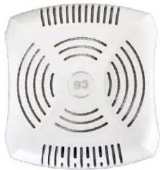
2.2 AP-93
This section introduces the Aruba AP-93 Wireless Access Point (AP) with FIPS 140-2 Level 2 validation. It describes the purpose of the AP, its physical attributes, and its interfaces.
Figure 2 - AP-93 Wireless Access Point
natural_image
White square electronic device with concentric circular ventilation slots and a central indicator (no text or symbols visible)The Aruba AP-93 is robust-performance 802.11n (2x2:2) MIMO, single radio supporting 2.4 GHz or 5 GHz (802.11a/ b/g/n), indoor wireless access points capable of delivering wireless data rates of up to 300Mbps. This multi-function access point provides wireless LAN access, air monitoring, and wireless intrusion detection and prevention. The access point works in conjunction with Aruba Mobility Controllers to deliver high-speed, secure user-centric network services in education, enterprise, finance, government, healthcare, and retail applications.
2.2.1 Physical Description
The Aruba AP-93 series Access Point is a multi-chip standalone cryptographic module consisting of hardware and software, all contained in a hard plastic case. The module contains 802.11 a/b/g/n transceiver and 2 integrated omni-directional multi-band dipole antenna elements (supporting up to 2x2 MIMO with spatial diversity).
The plastic case physically encloses the complete set of hardware and software components and represents the cryptographic boundary of the module.
The Access Point configuration tested during the cryptographic module testing included:
| Aruba Part Number | Dell Corresponding Part Number |
| AP-93-F1 | W-AP93-F1 |
The exact firmware versions tested were:
- ArubaOS_6xx_6.1.2.3-FIPS
• Dell_PCW_6xx_6.1.2.3-FIPS
2.2.1.1 Dimensions/Weight
The AP has the following physical dimensions:
- 120 mm x 130 mm x 35 mm (4.7" x 5.1" x 1.4")
• 255 g (9 oz)
2.2.1.2 Interfaces
The module provides the following network interfaces:
• 1 x 10/100/1000 Base-T Ethernet (RJ45) Auto-sensing link speed and MDI/MDX
- Antenna (internal)
• 1 x RJ-45 console interface
The module provides the following power interfaces:
• 48 V DC 802.3af power over Ethernet
- 12 V DC for external AC supplied power (adapter sold separately)
2.2.1.3 Indicator LEDs
There are 4 bicolor (power, ENET and WLAN) LEDs which operate as follows:
Table 3- AP-93 Indicator LEDs
| Label | Function | Action | Status |
| PWR | AP power / ready status | Off | No power to AP |
| Red | Initial power-up condition | ||
| Flashing – Green | Device booting, not ready | ||
| On – Green | Device ready | ||
| ENET | Ethernet Network Link Status / Activity | Off | Ethernet link unavailable |
| On – Amber | 10/100Mbs Ethernet link negotiated | ||
| On – Green | 1000Mbs Ethernet link negotiated | ||
| Flashing | Ethernet link activity | ||
| 11b/g/n | 2.4GHz Radio Status | Off | 2.4GHz radio disabled |
| On - Amber | 2.4GHz radio enabled in WLAN mode | ||
| On - Green | 2.4GHz radio enabled in 802.11n mode | ||
| Flashing - Green | 2.4GHz Air monitor or RF protect sensor | ||
| 11a/n | 5GHz Radio Status | Off | 5GHz radio disabled |
| On - Amber | 5GHz radio enabled in WLAN mode | ||
| On - Green | 5GHz radio enabled in 802.11n mode | ||
| Flashing - Green | 5GHz Air monitor or RF protect sensor |
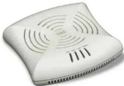
2.3 AP-105 Series
This section introduces the Aruba AP-120 series Wireless Access Points (APs) with FIPS 140-2 Level 2 validation. It describes the purpose of the AP, its physical attributes, and its interfaces.
Figure 3 - AP-105 Wireless Access Point
natural_image
White wireless router with ventilation grille and indicator lights (no visible text or symbols)The Aruba AP-105 is high-performance 802.11n (2x2:2) MIMO, dual-radio (concurrent 802.11a/n + b/g/n) indoor wireless access points capable of delivering combined wireless data rates of up to 600Mbps. This multi-function access point provides wireless LAN access, air monitoring, and wireless intrusion detection and prevention over the 2.4GHz and 5GHz RF spectrum. The access point works in conjunction with Aruba Mobility Controllers to deliver high-speed, secure user-centric network services in education, enterprise, finance, government, healthcare, and retail applications.
2.3.1 Physical Description
The Aruba AP-105 Access Point is a multi-chip standalone cryptographic module consisting of hardware and software, all contained in a hard plastic case. The module contains two dual-band 2.4-GHz/5-GHz 802.11 a/b/g/n transceivers, and 4 x integrated, omni-directional antenna elements (supporting up to 2x2 MIMO with spatial diversity).
The plastic case physically encloses the complete set of hardware and software components and represents the cryptographic boundary of the module.
The Access Point configuration tested during the cryptographic module testing included:
| Aruba Part Number | Dell Corresponding Part Number |
| AP-105-F1 | W-AP105-F1 |
The exact firmware versions tested were:
- ArubaOS_6xx_6.1.2.3-FIPS
• Dell_PCW_6xx_6.1.2.3-FIPS
2.3.1.1 Dimensions/Weight
The AP has the following physical dimensions:
- 132 mm x 135 mm x 45 mm (5.2" x 5.3" x 1.8")
- 0.3 kg (10.56 oz)
2.3.1.2 Interfaces
The module provides the following network interfaces:
• 1 x 10/100/1000 Base-T Ethernet (RJ45) Auto-sensing link speed and MDI/MDX
- Antenna (internal)
• 1 x RJ-45 console interface
The module provides the following power interfaces:
• 48 V DC 802.3af power over Ethernet
- 12 V DC for external AC supplied power (adapter sold separately)
2.3.1.3 Indicator LEDs
There are 4 bicolor (power, ENET and WLAN) LEDs which operate as follows:
Table 4- AP-105 Indicator LEDs
| Label | Function | Action | Status |
| PWR | AP power / ready status | Off | No power to AP |
| Red | Initial power-up condition | ||
| Flashing – Green | Device booting, not ready | ||
| On – Green | Device ready | ||
| ENET | Ethernet Network Link Status / Activity | Off | Ethernet link unavailable |
| On – Amber | 10/100Mbs Ethernet link negotiated | ||
| On – Green | 1000Mbs Ethernet link negotiated | ||
| Flashing | Ethernet link activity | ||
| 11b/g/n | 2.4GHz Radio Status | Off | 2.4GHz radio disabled |
| On – Amber | 2.4GHz radio enabled in WLAN mode | ||
| On – Green | 2.4GHz radio enabled in 802.11n mode | ||
| Flashing - Green | 2.4GHz Air monitor or RFprotect sensor | ||
| 11a/n | 5GHz Radio Status | Off | 5GHz radio disabled |
| On - Amber | 5GHz radio enabled in WLAN mode | ||
| On – Green | 5GHz radio enabled in 802.11n mode | ||
| Flashing - Green | 5GHz Air monitor or RFprotect sensor |
2.4 AP-175 Series
This section introduces the Aruba AP-175 series Wireless Access Points (APs) with FIPS 140-2 Level 2 validation. It describes the purpose of the AP, its physical attributes, and its interfaces.
Figure 4 - AP-175 Wireless Access Point

natural_image
Exterior view of a white rectangular electronic device with ports and connectors (no visible text or symbols)The Aruba AP-175 is high-performance 802.11n (2x2:2) MIMO, dual-radio (concurrent 802.11a/n + b/g/n) indoor wireless access points capable of delivering combined wireless data rates of up to 600Mbps. This multi-function access point provides wireless LAN access, air monitoring, and wireless intrusion detection and prevention over the 2.4GHz and 5GHz RF spectrum. The multifunction AP-175 is an affordable, fully hardened outdoor 802.11n access point (AP) that provides maximum deployment flexibility in high-density campuses, storage yards, warehouses, container/transportation facilities, extreme industrial production areas and other harsh environments.
2.4.1 Physical Description
The Aruba AP-175 Access Point is a multi-chip standalone cryptographic module consisting of hardware and software, all contained in a hard case. The module contains two 802.11 a/b/g/n transceivers, and 4 x N-type female interfaces (2 x 2.4 GHz, 2 x 5 GHz) for external antenna support (supports MIMO)
The hard case physically encloses the complete set of hardware and software components and represents the cryptographic boundary of the module.
The Access Point configuration tested during the cryptographic module testing included:
| Aruba Part Number | Dell Corresponding Part Number |
| AP-175P-F1 | W-AP175P-F1 |
| AP-175AC-F1 | W-AP175AC-F1 |
| AP-175DC-F1 | W-AP175DC-F1 |
The exact firmware versions tested were:
- ArubaOS_6xx_6.1.2.3-FIPS
• Dell_PCW_6xx_6.1.2.3-FIPS
2.4.1.1 Dimensions/Weight
The AP has the following physical dimensions:
- 260 mm x 240 mm x 105 mm (10.2" x 9.4" x4.1")
• 3.25 kg (7 lb)
2.4.1.2 Interfaces
The module provides the following network interfaces:
• 1 x 10/100/1000 Base-T Ethernet (RJ45) Auto-sensing link speed and MDI/MDX
- Antenna
- 4 x N-Type female antenna interfaces
• 1 x RJ-45 console interface
The module provides the following power interfaces:
• AP-175P: 48-volt DC 802.3at power over Ethernet (PoE+)
• AP-175AC: 100-240 volt AC from external AC power source
• AP-175DC: 12-48 volt DC from external DC power source
2.4.1.3 Indicator LEDs
There is an array of LEDs which operate as follows:
Table 5- AP-175 Indicator LEDs
| Label | LED Position | Function | Action | Status |
| PWR | D11 | AP power / system status | Off | No power to AP |
| Red | System Alarm | |||
| Flashing - Green | Power did not connect well or equipment failure | |||
| On - Green | Device ready | |||
| ENET0 | D15 | Ethernet Network Link Status / Activity | Off | Ethernet link unavailable |
| On - Yellow | 10/100Mbs Ethernet link negotiated | |||
| On - Green | 1000Mbs Ethernet link negotiated | |||
| Flashing | Ethernet link activity | |||
| WLAN0 | D6 | Radio0 Status | Off | Radio0 disabled |
| On - Orange | Radio0 enabled | |||
| WLAN1 | D1 | Radio1 Status | Off | Radio1 disabled |
| On - Blue | Radio1 enabled | |||
| SS1 | D7/D2 | Signal Strength (Radio0/Radio1) least significant bit | On - Orange/Blue(For Radio0: Orange and For Radio1: Blue)Off | SS1 to SS4 LEDs turn on/off depending on the signal strength of the current radio neighbors. Stronger the signal, more LEDs get lit starting with SS1 (least signal strength indicator) all the way to SS4 (highest signal strength indicator). |
| SS2 | D8/D3 | Signal Strength (Radio0/Radio1) second most significant bit | ||
| SS3 | D9/D4 | Signal Strength (Radio0/Radio1) least significant bit | ||
| SS4 | D10/D5 | Signal Strength (Radio0/Radio1) most significant bit |
3 Module Objectives
This section describes the assurance levels for each of the areas described in the FIPS 140-2 Standard. In addition, it provides information on placing the module in a FIPS 140-2 approved configuration.
3.1 Security Levels
| Section | Section Title | Level |
| 1 | Cryptographic Module Specification | 2 |
| 2 | Cryptographic Module Ports and Interfaces | 2 |
| 3 | Roles, Services, and Authentication | 2 |
| 4 | Finite State Model | 2 |
| 5 | Physical Security | 2 |
| 6 | Operational Environment | N/A |
| 7 | Cryptographic Key Management | 2 |
| 8 | EMI/EMC | 2 |
| 9 | Self-tests | 2 |
| 10 | Design Assurance | 2 |
| 11 | Mitigation of Other Attacks | N/A |
3.2 Physical Security
The Aruba Wireless AP is a scalable, multi-processor standalone network device and is enclosed in a robust plastic housing. The AP enclosure is resistant to probing (please note that this feature has not been tested as part of the FIPS 140-2 validation) and is opaque within the visible spectrum. The enclosure of the AP has been designed to satisfy FIPS 140-2 Level 2 physical security requirements.
3.2.1 Applying TELs
The Crypto Officer is responsible for securing and having control at all times of any unused tamper evident labels. The Crypto Officer should employ TELs as follows:
• Before applying a TEL, make sure the target surfaces are clean and dry.
- Do not cut, trim, punch, or otherwise alter the TEL.
- Apply the wholly intact TEL firmly and completely to the target surfaces.
- Ensure that TEL placement is not defeated by simultaneous removal of multiple modules.
- Allow 24 hours for the TEL adhesive seal to completely cure.
• Record the position and serial number of each applied TEL in a security log.
For physical security, the AP requires Tamper-Evident Labels (TELs) to allow detection of the opening of the device, and to block the serial console port (on the bottom of the device). The tamper-evident labels shall be installed for the module to operate in a FIPS approved mode of operation. To protect the device from tampering, TELs should be applied by the Crypto Officer as pictured below:
3.2.2 AP-92 TEL Placement
This section displays all the TEL locations of the Aruba AP-92. The AP-92 requires a minimum of 3 TELs to be applied as follows:
3.2.2.1 To detect access to restricted ports:
- Spanning the serial port
3.2.2.2 To detect opening of the chassis cover:
-
Spanning the bottom and top chassis covers on the right side
-
Spanning the bottom and top chassis covers on the left side
Following is the TEL placement for the AP-92:
Figure 5 - AP-92 Tel placement front view

natural_image
White wireless router with ventilation slots and gold connectors (no visible text or symbols)Figure 6 - Aruba AP-92 Tel placement left view
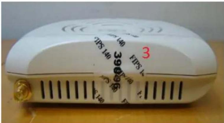
Figure7 - Aruba AP-92 Tel placement right view

Figure 8 - Aruba AP-92 Tel placement top view

Figure 9 - Aruba AP-92 Tel placement bottom view

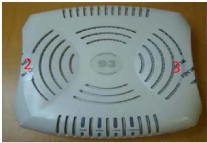
3.2.3 AP-93 TEL Placement
This section displays all the TEL locations of the Aruba AP-93. The AP-93 requires a minimum of 3 TELs to be applied as follows:
3.2.3.1 To detect access to restricted ports:
- Spanning the serial port
3.2.3.2 To detect opening of the chassis cover:
- Spanning the bottom and top chassis covers on the left side
- Spanning the bottom and top chassis covers on the right side
Following is the TEL placement for the AP-93:
Figure 10 - Aruba AP-93 Tel placement front view

natural_image
White wireless router with ventilation grilles and ventilation slots, placed on a wooden surface (no visible text or symbols)Figure 11 - Aruba AP-93 Tel placement left view

Figure 12 - Aruba AP-93 Tel placement right view

Figure 13 - Aruba AP-93 Tel placement bottom view
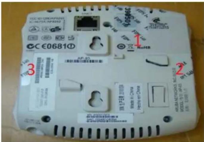
Figure 14 - Aruba AP-93 Tel placement top view
3.2.4 AP-105 TEL Placement
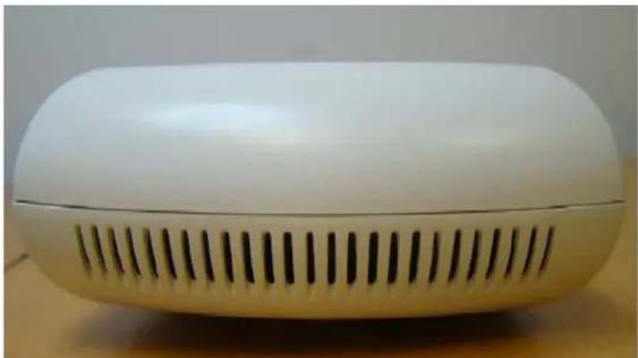
This section displays all the TEL locations of the Aruba AP-105. The AP-105 requires a minimum of 3 TELs to be applied as follows:
3.2.4.1 To detect opening of the chassis cover:
- Spanning the bottom and top chassis covers on the left side
- Spanning the bottom and top chassis covers on the right side
3.2.4.2 To detect access to restricted ports:
- Spanning the serial port
Following is the TEL placement for the AP-105:
Figure 15 - Aruba AP-105 Tel placement front view
natural_image
White electronic device with ventilation grille and lid (no visible text or symbols)Figure 16 - Aruba AP-105 Tel placement left view

Figure 17 - Aruba AP-105 Tel placement right view

Figure 18 - Aruba AP-105 Tel placement top view
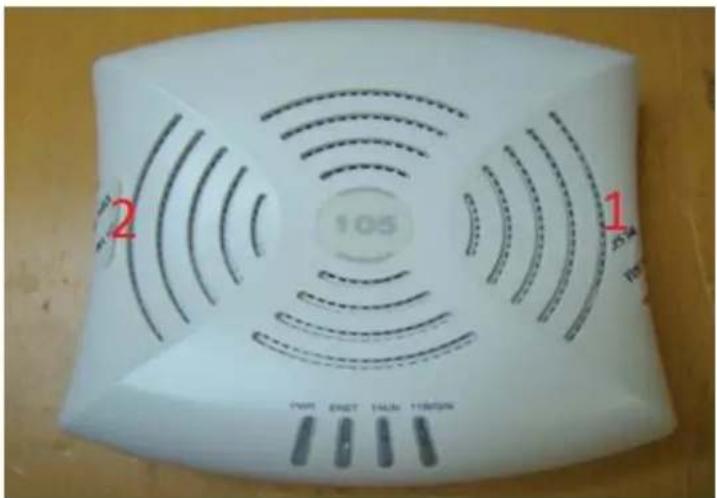
Figure 19 - Aruba AP-105 Tel placement bottom view

3.2.5 AP-175 TEL Placement
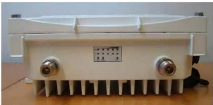
This section displays all the TEL locations of the Aruba AP-175. The AP-175 requires a minimum of 6 TELs to be applied as follows:
3.2.5.1 To detect access to restricted ports:
- Spanning the USB console port
- Spanning the power connector plug (AP-175P only)
- Spanning the hex screw
3.2.5.2 To detect opening of the chassis cover:
- Spanning the top and bottom chassis covers on the left side
- Spanning the top and bottom chassis covers on the right side
Following is the TEL placement for the AP-175:
Figure 19 - Aruba AP-175 Tel placement front view

Figure 20 - Aruba AP-175 Tel placement back view
natural_image
White electronic device with two metallic connectors and a small labeled panel (no visible text or symbols)Figure 21 - Aruba AP-175 Tel placement left view

Figure 22 - Aruba AP-175 Tel placement right view
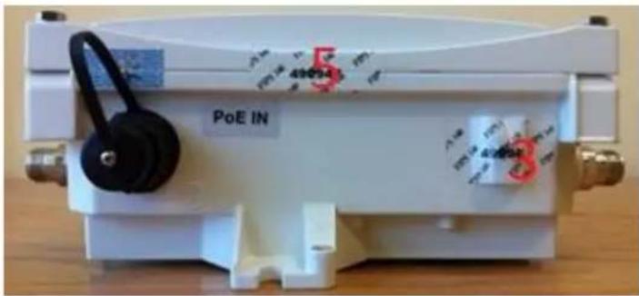
Figure 23 - Aruba AP-175 Tel placement top view

Figure 24 - Aruba AP-175 Tel placement bottom view

natural_image
White industrial heat exchanger housing with cooling fins and mounting feet (no text or symbols visible)3.2.6 Inspection/Testing of Physical Security Mechanisms
| Physical Security Mechanism | Recommended Test Frequency | Guidance |
| Tamper-evident labels (TELs) | Once per month | Examine for any sign of removal, replacement, tearing, etc. See images above for locations of TELs |
| Opaque module enclosure | Once per month | Examine module enclosure for any evidence of new openings or other access to the module internals. |
3.3 Modes of Operation
The module has the following FIPS approved modes of operations:
- Remote AP (RAP) FIPS mode – When the module is configured as a Remote AP, it is intended to be deployed in a remote location (relative to the Mobility Controller). The module provides cryptographic processing in the form of IPSec for all traffic to and from the Mobility Controller.
- Control Plane Security (CPSec) protected AP FIPS mode – When the module is configured as a Control Plane Security protected AP it is intended to be deployed in a local/private location (LAN, WAN, MPLS) relative to the Mobility Controller). The module provides cryptographic processing in the form of IPSec for all Control traffic to and from the Mobility Controller.
- Remote Mesh Portal FIPS mode – When the module is configured in Mesh Portal mode, it is intended to be connected over a physical wire to the mobility controller. These modules serve as the connection point between the Mesh Point and the Mobility Controller. Mesh Portals communicate with the Mobility Controller through IPSec and with Mesh Points via 802.11i session. The Crypto Officer role is the Mobility Controller that authenticates via IKEv1/IKEv2 pre-shared key or RSA certificate authentication method, and Users are the "n" Mesh Points that authenticate via 802.11i preshared key.
- Mesh Point FIPS MODE – an AP that establishes all wireless path to the Remote Mesh portal in FIPS mode over 802.11 and an IPSec tunnel via the Remote Mesh Portal to the controller.
This section explains how to place the module in FIPS mode in either Remote AP FIPS mode, Control Plane Security AP FIPS Mode, Remote Mesh Portal FIPS mode or Mesh Point FIPS Mode. How to verify that it is in FIPS mode. An important point in the Aruba APs is that to change configurations from any one mode to any other mode requires the module to be re-provisioned and rebooted before any new configured mode can be enabled.
The access point is managed by an Aruba Mobility Controller in FIPS mode, and access to the Mobility Controller's administrative interface via a non-networked general purpose computer is required to assist in placing the module in FIPS mode. The controller used to provision the AP is referred to below as the “staging controller”. The staging controller must be provisioned with the appropriate firmware image for the module, which has been tested to FIPS 140-2, prior to initiating AP provisioning.
After setting up the Access Point by following the basic installation instructions in the module User Manual, the Crypto Officer performs the following steps:
3.3.1 Configuring Remote AP FIPS Mode
- Apply TELs according to the directions in section 3.2
- Log into the administrative console of the staging controller
- Deploying the AP in Remote FIPS mode configure the controller for supporting Remote APs, For detailed instructions and steps, see Section "Configuring the Secure Remote Access Point Service" in Chapter "Remote Access Points" of the Aruba OS User Manual.
-
Enable FIPS mode on the controller. This is accomplished by going to the Configuration > Network > Controller > System Settings page (this is the default page when you click the Configuration tab), and clicking the FIPS Mode for Mobility Controller Enable checkbox.
-
Enable FIPS mode on the AP. This accomplished by going to the Configuration > Wireless > AP Configuration > AP Group page. There, you click the Edit button for the appropriate AP group, and then select AP > AP System Profile. Then, check the "Tips Enable" box, check "Apply", and save the configuration.
-
If the staging controller does not provide PoE, either ensure the presence of a PoE injector for the LAN connection between the module and the controller, or ensure the presence of a DC power supply appropriate to the particular model of the module.
- Connect the module via an Ethernet cable to the staging controller; note that this should be a direct connection, with no intervening network or devices; if PoE is being supplied by an injector, this represents the only exception. That is, nothing other than a PoE injector should be present between the module and the staging controller.
- Once the module is connected to the controller by the Ethernet cable, navigate to the Configuration > Wireless > AP Installation page, where you should see an entry for the AP. Select that AP, click the "Provision" button, which will open the provisioning window. Now provision the AP as Remote AP by filling in the form appropriately. Detailed steps are listed in Section "Provisioning an Individual AP" of Chapter "The Basic User-Centric Networks" of the Aruba OS User Guide. Click "Apply and Reboot" to complete the provisioning process.
a. During the provisioning process as Remote AP if Pre-shared key is selected to be the Remote IP Authentication Method, the IKE pre-shared key (which is at least 8 characters in length) is input to the module during provisioning. Generation of this key is outside the scope of this policy. In the initial provisioning of an AP, this key will be entered in plaintext; subsequently, during provisioning, it will be entered encrypted over the secure IPSec session. If certificate based authentication is chosen, AP's RSA key pair is used to authenticate AP to controller during IPSec. AP's RSA private key is contained in the AP's non volatile memory and is generated at manufacturing time in factory.
-
Via the logging facility of the staging controller, ensure that the module (the AP) is successfully provisioned with firmware and configuration
-
Terminate the administrative session
-
Disconnect the module from the staging controller, and install it on the deployment network; when power is applied, the module will attempt to discover and connect to an Aruba Mobility Controller on the network.
3.2 Configuring Control Plane Security (CPSec) protected AP FIPS mode
- Apply TELs according to the directions in section 3.2
- Log into the administrative console of the staging controller
- Deploying the AP in CPSec AP mode, configure the staging controller with CPSec under Configuration > Controller > Control Plane Security tab. AP will authenticate to the controller using certificate based authentication to establish IPSec. AP is configured with RSA key pair at manufacturing. AP's certificate is signed by Aruba Certification Authority (trusted by all Aruba controllers) and the AP's RSA private key is stored in non-volatile memory. Refer to "Configuring Control Plane Security" Section in ArubaOS User Manual for details on the steps.
- Enable FIPS mode on the controller. This is accomplished by going to the Configuration > Network > Controller > System Settings page (this is the default page when you click the Configuration tab), and clicking the FIPS Mode for Mobility Controller Enable checkbox.
- Enable FIPS mode on the AP. This accomplished by going to the Configuration > Wireless > AP Configuration > AP Group page. There, you click the Edit button for the appropriate AP group, and then select AP > AP System Profile. Then, check the "Fips Enable" box, check "Apply", and save the configuration.
-
If the staging controller does not provide PoE, either ensure the presence of a PoE injector for the LAN connection between the module and the controller, or ensure the presence of a DC power supply appropriate to the particular model of the module
-
Connect the module via an Ethernet cable to the staging controller; note that this should be a direct connection, with no intervening network or devices; if PoE is being supplied by an injector, this represents the only exception. That is, nothing other than a PoE injector should be present between the module and the staging controller.
- Once the module is connected to the controller by the Ethernet cable, navigate to the Configuration > Wireless > AP Installation page, where you should see an entry for the AP. Select that AP, click the “Provision” button, which will open the provisioning window. Now provision the CPSec Mode by filling in the form appropriately. Detailed steps are listed in Section “Provisioning an Individual AP” of Chapter “The Basic User-Centric Networks” of the Aruba OS User Guide. Click “Apply and Reboot” to complete the provisioning process.
a. For CPSec AP mode, the AP always uses certificate based authentication to establish IPSec connection with controller. AP uses the RSA key pair assigned to it at manufacturing to authenticate itself to controller during IPSec. Refer to “Configuring Control Plane Security” Section in Aruba OS User Manual for details on the steps to provision an AP with CPSec enabled on controller.
-
Via the logging facility of the staging controller, ensure that the module (the AP) is successfully provisioned with firmware and configuration
-
Terminate the administrative session
-
Disconnect the module from the staging controller, and install it on the deployment network; when power is applied, the module will attempt to discover and connect to an Aruba Mobility Controller on the network.
3.3 Configuring Remote Mesh Portal FIPS Mode
- Apply TELs according to the directions in section 3.2
- Log into the administrative console of the staging controller
- Deploying the AP in Remote Mesh Portal mode, create the corresponding Mesh Profiles on the controller as described in detail in Section "Mesh Profiles" of Chapter "Secure Enterprise Mesh" of the Aruba OS User Manual.
a. For mesh configurations, configure a WPA2 PSK which is 16 ASCII characters or 64 hexadecimal digits in length; generation of such keys is outside the scope of this policy.
- Enable FIPS mode on the controller. This is accomplished by going to the Configuration > Network > Controller > System Settings page (this is the default page when you click the Configuration tab), and clicking the FIPS Mode for Mobility Controller Enable checkbox.
- Enable FIPS mode on the AP. This accomplished by going to the Configuration > Wireless > AP Configuration > AP Group page. There, you click the Edit button for the appropriate AP group, and then select AP > AP System Profile. Then, check the "Fips Enable" box, check "Apply", and save the configuration.
- If the staging controller does not provide PoE, either ensure the presence of a PoE injector for the LAN connection between the module and the controller, or ensure the presence of a DC power supply appropriate to the particular model of the module.
- Connect the module via an Ethernet cable to the staging controller; note that this should be a direct connection, with no intervening network or devices; if PoE is being supplied by an injector, this represents the only exception. That is, nothing other than a PoE injector should be present between the module and the staging controller.
- Once the module is connected to the controller by the Ethernet cable, navigate to the Configuration > Wireless > AP Installation page, where you should see an entry for the AP. Select that AP, click the "Provision" button, which will open the provisioning window. Now provision
the AP as Remote Mesh Portal by filling in the form appropriately. Detailed steps are listed in Section “Provisioning an Individual AP” of Chapter “The Basic User-Centric Networks” of the Aruba OS User Guide. Click “Apply and Reboot” to complete the provisioning process.
a. During the provisioning process as Remote Mesh Portal, if Pre-shared key is selected to be the Remote IP Authentication Method, the IKE pre-shared key (which is at least 8 characters in length) is input to the module during provisioning. Generation of this key is outside the scope of this policy. In the initial provisioning of an AP, this key will be entered in plaintext; subsequently, during provisioning, it will be entered encrypted over the secure IPSec session. If certificate based authentication is chosen, AP's RSA key pair is used to authenticate AP to controller during IPSec. AP's RSA private key is contained in the AP's non volatile memory and is generated at manufacturing time in factory.
b. During the provisioning process as Remote Mesh Portal, the WPA2 PSK is input to the module via the corresponding Mesh cluster profile. This key is stored on flash encrypted.
-
Via the logging facility of the staging controller, ensure that the module (the AP) is successfully provisioned with firmware and configuration
-
Terminate the administrative session
-
Disconnect the module from the staging controller, and install it on the deployment network; when power is applied, the module will attempt to discover and connect to an Aruba Mobility Controller on the network.
To verify that the module is in FIPS mode, do the following:
-
Log into the administrative console of the Aruba Mobility Controller
-
Verify that the module is connected to the Mobility Controller
-
Verify that the module has FIPS mode enabled by issuing command "show ap ap-name
config" -
Terminate the administrative session
3.3.4 Configuring Remote Mesh Point FIPS Mode
-
Apply TELs according to the directions in section 3.2
-
Log into the administrative console of the staging controller
-
Deploying the AP in Remote Mesh Point mode, create the corresponding Mesh Profiles on the controller as described in detail in Section "Mesh Points" of Chapter "Secure Enterprise Mesh" of the Aruba OS User Manual.
a. For mesh configurations, configure a WPA2 PSK which is 16 ASCII characters or 64 hexadecimal digits in length; generation of such keys is outside the scope of this policy.
-
Enable FIPS mode on the controller. This is accomplished by going to the Configuration > Network > Controller > System Settings page (this is the default page when you click the Configuration tab), and clicking the FIPS Mode for Mobility Controller Enable checkbox.
-
Enable FIPS mode on the AP. This accomplished by going to the Configuration > Wireless > AP Configuration > AP Group page. There, you click the Edit button for the appropriate AP group, and then select AP > AP System Profile. Then, check the "Fips Enable" box, check "Apply", and save the configuration.
-
If the staging controller does not provide PoE, either ensure the presence of a PoE injector for the LAN connection between the module and the controller, or ensure the presence of a DC power supply appropriate to the particular model of the module.
-
Connect the module via an Ethernet cable to the staging controller; note that this should be a direct connection, with no intervening network or devices; if PoE is being supplied by an injector, this
represents the only exception. That is, nothing other than a PoE injector should be present between the module and the staging controller.
- Once the module is connected to the controller by the Ethernet cable, navigate to the Configuration > Wireless > AP Installation page, where you should see an entry for the AP. Select that AP, click the “Provision” button, which will open the provisioning window. Now provision the AP as Remote Mesh Portal by filling in the form appropriately. Detailed steps are listed in Section “Provisioning an Individual AP” of Chapter “The Basic User-Centric Networks” of the Aruba OS User Guide. Click “Apply and Reboot” to complete the provisioning process.
a. During the provisioning process as Remote Mesh Point, if Pre-shared key is selected to be the Remote IP Authentication Method, the IKE pre-shared key (which is at least 8 characters in length) is input to the module during provisioning. Generation of this key is outside the scope of this policy. In the initial provisioning of an AP, this key will be entered in plaintext; subsequently, during provisioning, it will be entered encrypted over the secure IPSec session. If certificate based authentication is chosen, AP's RSA key pair is used to authenticate AP to controller during IPSec. AP's RSA private key is contained in the AP's non volatile memory and is generated at manufacturing time in factory.
b. During the provisioning process as Mesh Point, the WPA2 PSK is input to the module via the corresponding Mesh cluster profile. This key is stored on flash encrypted.
-
Via the logging facility of the staging controller, ensure that the module (the AP) is successfully provisioned with firmware and configuration
-
Terminate the administrative session
-
Disconnect the module from the staging controller, and install it on the deployment network; when power is applied, the module will attempt to discover and connect to an Aruba Mobility Controller on the network.
3.5 Verify that the module is in FIPS mode
For all the approved modes of operations in either Remote AP FIPS mode, Control Plane Security AP FIPS Mode, Remote Mesh Portal FIPS mode or Mesh Point FIPS Mode do the following to verify the module is in FIPS mode:
- Log into the administrative console of the Aruba Mobility Controller
- Verify that the module is connected to the Mobility Controller
- Verify that the module has FIPS mode enabled by issuing command "show ap ap-name
config" - Terminate the administrative session
3.4 Operational Environment
The operational environment is non-modifiable. The Operating System (OS) is Linux, a real-time multi-threaded operating system that supports memory protection between processes. Access to the underlying Linux implementation is not provided directly. Only Aruba-provided Crypto Officer interfaces are used. There is no user interface provided.
3.5 Logical Interfaces
The physical interfaces are divided into logical interfaces defined by FIPS 140-2 as described in the following table.
Table 6 - FIPS 140-2 Logical Interfaces
| FIPS 140-2 Logical Interface | Module Physical Interface |
| Data Input Interface | 10/100/1000 Ethernet Ports802.11a/b/g/n Radio Transceiver |
| Data Output Interface | 10/100/1000 Ethernet Ports802.11a/b/g/n Radio Transceiver |
| Control Input Interface | 10/100/1000 Ethernet Ports (PoE)5V power input jack |
| Status Output Interface | 10/100/1000 Ethernet Ports802.11a/b/g/n Radio TransceiverLEDs |
| Power Interface | Power Supply |
Data input and output, control input, status output, and power interfaces are defined as follows:
• Data input and output are the packets that use the networking functionality of the module.
- Control input consists of manual control inputs for power and reset through the power interfaces. It also consists of all of the data that is entered into the access point while using the management interfaces.
- Status output consists of the status indicators displayed through the LEDs, the status data that is output from the module while using the management interfaces, and the log file.
○ LEDs indicate the physical state of the module, such as power-up (or rebooting), utilization level, and activation state. The log file records the results of self-tests, configuration errors, and monitoring data.
- A power supply may be used to connect the electric power cable. Operating power may also be provided via Power Over Ethernet (POE) device when connected. The power is provided through the connected Ethernet cable.
- Console port is disabled when operating in each of FIPS modes.
The module distinguishes between different forms of data, control, and status traffic over the network ports by analyzing the packet headers and contents.
4 Roles, Authentication and Services
4.1 Roles
The module supports the roles of Crypto Officer, User, and Wireless Client; no additional roles (e.g., Maintenance) are supported. Administrative operations carried out by the Aruba Mobility Controller map to the Crypto Officer role. The Crypto Officer has the ability to configure, manage, and monitor the module, including the configuration, loading, and zeroization of CSPs.
Defining characteristics of the roles depend on whether the module is configured as a Remote AP mode or as a Remote Mesh Portal mode.
- Remote AP:
○ Crypto Officer Role: the Crypto Officer is the Aruba Mobility Controller that has the ability to configure, manage, and monitor the module, including the configuration, loading, and zeroization of CSPs.
- User role: in the standard configuration, the User operator shares the same services and authentication techniques as the Mobility Controller in the Crypto Officer role.
- Wireless Client role: in Remote AP configuration, a wireless client can create a connection to the module using WPA2 and access wireless network access/bridging services. In advanced Remote AP configuration, when Remote AP cannot communicate with the controller, the wireless client role authenticates to the module via WPA2-PSK only.
- CPSec AP:
○ Crypto Officer Role: the Crypto Officer is the Aruba Mobility Controller that has the ability to configure, manage, and monitor the module, including the configuration, loading, and zeroization of CSPs.
- User role: in the standard configuration, the User operator shares the same services and authentication techniques as the Mobility Controller in the Crypto Officer
- Wireless Client role: in CPSec AP configuration, a wireless client can create a connection to the module using WPA2 and access wireless network access services.
- Mesh AP (Mesh Point or Remote Mesh Portal configuration):
○ Crypto Officer role: the Crypto Officer role is the Aruba Mobility Controller that has the ability to configure, manage, and monitor the module, including the configuration, loading, and zeroization of CSPs.
- User role: the second (or third, or nth) AP in a given mesh cluster
- Wireless Client role: in Mesh AP configuration, a wireless client can create a connection to the module using WPA2 and access wireless network access services.
4.1.1 Crypto Officer Authentication
In each of FIPS approved modes, the Aruba Mobility Controller implements the Crypto Officer role. Connections between the module and the mobility controller are protected using IPSec. Crypto Officer authentication is accomplished via either proof of possession of the IKEv1/IKEv2 pre-shared key or RSA certificate, which occurs during the IKEv1/IKEv2 key exchange.
4.1.2 User Authentication
Authentication for the User role depends on the module configuration. When the module is configured as a Remote Mesh Portal FIPS mode and Remote Mesh Point FIPS mode, the User role is authenticated via the WPA2 pre-shared key. When the module is configured as a Remote AP FIPS mode and CPSec protected AP FIPS mode, the User role is authenticated via the same IKEv1/IKEv2 pre-shared key/RSA certificate that is used by the Crypto Officer
4.1.3 Wireless Client Authentication
The wireless client role defined in each of FIPS approved modes authenticates to the module via WPA2. Please notice that WEP and/or Open System configurations are not permitted in FIPS mode. In advanced Remote AP configuration, when Remote AP cannot communicate with the controller, the wireless client role authenticates to the module via WPA2-PSK only.
4.1.4 Strength of Authentication Mechanisms
The following table describes the relative strength of each supported authentication mechanism.
| Authentication Mechanism | Mechanism Strength |
| IKEv1/IKEv2 shared secret (CO role) | For IKEv1/IKEv2, there are a 95^8 (=6.63 x 10^15) possible pre-shared keys. In order to test the guessed key, the attacker must complete an IKEv1/IKEv2 aggressive mode exchange with the module. IKEv1/IKEv2 aggressive mode consists of a 3 packet exchange, but for simplicity, let's ignore the final packet sent from the AP to the attacker.An IKEv1/IKEv2 aggressive mode initiator packet with a single transform, using Diffie-Hellman group 2, and having an eight character group name has an IKEv1/IKEv2 packet size of 256 bytes. Adding the eight byte UDP header and 20 byte IP header gives a total size of 284 bytes (2272 bits).The response packet is very similar in size, except that it also contains the HASH_R payload (an additional 16 bytes), so the total size of the second packet is 300 bytes (2400 bits).Assuming a link speed of 1Gbits/sec (this is the maximum rate supported by the module), this gives a maximum idealized guessing rate of 60,000,000,000 / 4,672 = 12,842,466 guesses per minute. This means the odds of guessing a correct key in one minute is less than 12,842,466/(6.63x10^15) = 1.94 x 10^-9, which is much less than 1 in 10^5. |
| Wireless Client WPA2-PSK (Wireless Client role) | For WPA2-PSK there are at least 95^16 (=4.4 x 10^31) possible combinations. In order to test a guessed key, the attacker must complete the 4-way handshake with the AP. Prior to completing the 4-way handshake, the attacker must complete the 802.11 association process. That process involves the following packet exchange:Attacker sends Authentication request (at least 34 bytes)AP sends Authentication response (at least 34 bytes)Attacker sends Associate Request (at least 36 bytes)AP sends Associate Response (at least 36 bytes)Total bytes sent: at least 140. Note that since we do not include the actual 4-way handshake, this is less than half the bytes that would actually be sent, so the numbers we derive will absolutely bound the answer.The theoretical bandwidth limit for IEEE 802.11n is 300Mbit, which is 37,500,000 bytes/sec. In the real world, actual throughput is significantly less than this, but we will use this idealized number to ensure that our estimate is very conservative.This means that the maximum number of associations (assume no delays, no inter-frame gaps) that could be completed is less than 37,500,000/214 = 267,857 per second, or 16,071,429 associations per minute. This means that an attacker could certainly not try more than this many keys per second (it would actually be MUCH less, due to the added overhead of the 4-way handshake in each case), and the probability of a successful attack in any 60 second interval MUST be less than 16,071,429/(4.4 x 10^31), or roughly 1 in 10^25, which is much less than 1 in 10^5. |
| Mesh AP WPA2 PSK (User role) | Same as Wireless Client WPA2-PSK above |
| RSA Certificate based authentication (CO role) | The module supports RSA 1024 bit keys and 2048-bit RSA keys. RSA 1024 bit keys correspond to 80 bits of security. The probability of a successful random attempt is 1/(2^80), which is less than 1/1,000,000. The probability of a success with multiple consecutive attempts in a one-minute period is less than 1/100,000. |
4.2 Services
The module provides various services depending on role. These are described below.
4.2.1 Crypto Officer Services
The CO role in each of FIPS modes defined in section 3.3 has the same services
| Service | Description | CSPs Accessed (see section 6 below for complete description of CSPs) |
| FIPS mode enable/disable | The CO selects/de-selects FIPS mode as a configuration option. | None. |
| Key Management | The CO can configure/modify the IKEv1/IKEv2 shared secret (The RSA private key is protected by non-volatile memory and cannot be modified) and the WPA2 PSK (used in advanced Remote AP configuration). Also, the CO/User implicitly uses the KEK to read/write configuration to non-volatile memory. | IKEv1/IKEv2 shared secretWPA2 PSKKEK |
| Remotely reboot module | The CO can remotely trigger a reboot | KEK is accessed when configuration is read during reboot. The firmware verification key and firmware verification CA key are accessed to validate firmware prior to boot. |
| Self-test triggered by CO/User reboot | The CO can trigger a programmatic reset leading to self-test and initialization | KEK is accessed when configuration is read during reboot. The firmware verification key and firmware verification CA key are accessed to validate firmware prior to boot. |
| Update module firmware | The CO can trigger a module firmware update | The firmware verification key and firmware verification CA key are accessed to validate firmware prior to writing to flash. |
| Configure non-security related module parameters | CO can configure various operational parameters that do not relate to security | None. |
| Creation/use of secure management session between module and CO | The module supports use of IPSec for securing the management channel. | IKEv1/IKEv2 Preshared SecretDH Private KeyDH Public KeyIPSec session encryption keysIPSec session authentication keysRSA key pair |
| Creation/use of secure mesh channel | The module requires secure connections between mesh points using 802.11i | WPA2-PSK802.11i PMK802.11i PTK802.11i EAPOL MIC Key802.11i EAPOL Encryption Key802.11i AES-CCM key802.11i GMK802.11i GTK802.11i AES-CCM key |
| System Status | CO may view system status information through the secured management channel | See creation/use of secure management session above. |
4.2.2 User Services
The User services defined in Remote AP FIPS mode and CPSec protected AP FIPS mode shares the same services with the Crypto Officer role, please refer to Section 4.2.1, "Crypto Officer Services". The following services are provided for the User role defined in Remote Mesh Portal FIPS mode and Remote Mesh Point FIPS mode:
| Service | Description | CSPs Accessed (see section 6 below for complete description of CSPs) |
| Generation and use of 802.11i cryptographic keys | When the module is in mesh configuration, the inter-module mesh links are secured with 802.11i. | 802.11i PMK802.11i PTK802.11i EAPOL MIC Key802.11i EAPOL Encryption Key802.11i AES-CCM key802.11i GMK802.11i GTK |
| Use of WPA pre-shared key for establishment of IEEE 802.11i keys | When the module is in mesh configuration, the inter-module mesh links are secured with 802.11i. This is authenticated with a shared secret | WPA2 PSK |
4.2.3 Wireless Client Services
The following module services are provided for the Wireless Client role in each of FIPS approved modes defined in section 3.3.
| Service | Description | CSPs Accessed (see section 6 below for complete description of CSPs) |
| Generation and use of 802.11i cryptographic keys | In all modes, the links between the module and wireless client are secured with 802.11i. | 802.11i PMK802.11i PTK802.11i EAPOL MIC Key802.11i EAPOL Encryption Key802.11i AES-CCM key802.11i GMK802.11i GTK |
| Use of WPA pre-shared key for establishment of IEEE 802.11i keys | When the module is in advanced Remote AP configuration, the links between the module and the wireless client are secured with 802.11i. This is authenticated with a shared secret only. | WPA2 PSK |
| Wireless bridging services | The module bridges traffic between the wireless client and the wired network. | None |
4.2.4 Unauthenticated Services
The module provides the following unauthenticated services, which are available regardless of role. No CSPs are accessed by these services.
- System status – SYSLOG and module LEDs
• 802.11 a/b/g/n - FTP
- TFTP
• NTP - GRE tunneling of 802.11 wireless user frames (when acting as a "Local AP")
- Reboot module by removing/replacing power
- Self-test and initialization at power-on
5 Cryptographic Algorithms
FIPS-approved cryptographic algorithms have been implemented in hardware and firmware.
The firmware supports the following cryptographic implementations.
- ArubaOS OpenSSL AP Module implements the following FIPS-approved algorithms:
○ AES (Cert. #1851)
○ HMAC (Cert. #1099)
○ RNG (Cert. #970)
○ RSA (Cert. #934)
○ SHS (Cert. #1628)
○ Triple-DES (Cert. #1199)
- ArubaOS Module implements the following FIPS-approved algorithms:
○ AES (Cert. #1850)
○ HMAC (Cert. #1098)
○ RNG (Cert. #969)
○ RSA (Cert. #933)
o SHS (Cert. #1627)
○ Triple-DES (Cert. #1198)
- ArubaOS Kernel implements the following FIPS-approved algorithms:
○ AES (Cert. #1847)
○ HMAC (Cert. #1097)
○ SHS (Cert. #1625)
○ Triple-DES (Cert. #1197)
- ArubaOS UBOOT Bootloader implements the following FIPS-approved algorithms:
o RSA (Cert. #935)
○ SHS (Cert. #1629)
- Aruba Atheros hardware CCM implements the following FIPS-approved algorithms:
○ AES (Cert. #1849)
Non-FIPS Approved Algorithms
The cryptographic module implements the following non-approved algorithms that are not permitted for use in the FIPS 140-2 mode of operations:
• MD5
In addition, within the FIPS Approved mode of operation, the module supports the following allowed key establishment schemes:
- Diffie-Hellman (key agreement; key establishment methodology provides 80 bits of encryption strength)
6 Critical Security Parameters
The following Critical Security Parameters (CSPs) are used by the module:
| CSP | CSP TYPE | GENERATION | STORAGE And ZEROIZATION | USE |
| Key Encryption Key (KEK) | Triple-DES 168-bits key | Hard-coded | Stored in flash, zeroized by the ‘ap wipe out flash’ command. | Encrypts IKEv1/IKEv2 preshared keys and configuration parameters |
| IKEv1/IKEv2 Pre-shared secret | 64 character preshared key | CO configured | Encrypted in flash using the KEK; zeroized by updating through administrative interface, or by the ‘ap wipe out flash’ command. | Module and crypto officer authentication during IKEv1/IKEv2; entered into the module in plaintext during initialization and encrypted over the IPSec session subsequently. |
| IPSec session encryption keys | 168-bit Triple-DES, or 128/192/256 bit AES keys; | Established during Diffie-Hellman key agreement | Stored in plaintext in volatile memory; zeroized when session is closed or system powers off | Secure IPSec traffic |
| IPSec session authentication keys | HMAC SHA-1 keys | Established during Diffie-Hellman key agreement | Stored in plaintext in volatile memory; zeroized when session is closed or system powers off | Secure IPSec traffic |
| IKEv1/IKEv2 Diffie-Hellman Private key | 1024-bit Diffie-Hellman private key | Generated internally during IKEv1/IKEv2 negotiation | Stored in plaintext in volatile memory; zeroized when session is closed or system is powered off | Used in establishing the session key for IPSec |
| IKEv1/IKEv2 Diffie-Hellman shared secret | 128 bit Octet | Generated internally during IKEv1/IKEv2 negotiation | Stored in plaintext in volatile memory; zeroized when session is closed or system is powered off | IKEv1/IKEv2 payload integrity verification |
| ArubaOS OpenSSL RNG Seed for FIPS compliant ANSI X9.31, Appendix A2.4 using AES-128 Key algorithm | Seed (16 Bytes) | Derived using NON-FIPS approved HW RNG (/dev/urandom) | Stored in plaintext in volatile memory only; zeroized on reboot | Seed ANSI X9.31 RNG |
| ArubaOS OpenSSL RNG Seed key for FIPS compliant ANSI X9.31, Appendix A2.4 using AES-128 Key algorithm | Seed key (16 bytes, AES-128 Key algorithm) | Derived using NON-FIPS approved HW RNG (/dev/urandom) | Stored in plaintext in volatile memory only; zeroized on reboot | Seed ANSI X9.31 RNG |
| ArubaOS Cryptographic Module RNG Seed for FIPS compliant 186-2 General Purpose (X change Notice); SHA-1 RNG | Seed (64 bytes) | Derived using NON-FIPS approved HW RNG (/dev/urandom) | Stored in plaintext in volatile memory only; zeroized on reboot | Seed 186-2 General Purpose (X change Notice); SHA-1 RNG |
| ArubaOS Cryptographic Module RNG Seed key for FIPS compliant 186-2 General Purpose (X change Notice); SHA-1 RNG | Seed Key (64 bytes) | Derived using NON-FIPS approved HW RNG (/dev/urandom) | Stored in plaintext in volatile memory only; zeroized on reboot | Seed 186-2 General Purpose (X change Notice); SHA-1 RNG |
| WPA2 PSK | 16-64 character shared secret used to authenticate mesh connections and in remote AP advanced configuration | CO configured | Encrypted in flash using the KEK; zeroized by updating through administrative interface, or by the 'ap wipe out flash' command. | Used to derive the PMK for 802.11i mesh connections between APs and in advanced Remote AP connections; programmed into AP by the controller over the IPSec session. |
| 802.11i Pairwise Master Key (PMK) | 512-bit shared secret used to derive 802.11i session keys | Derived from WPA2 PSK | In volatile memory only; zeroized on reboot | Used to derive 802.11i Pairwise Transient Key (PTK) |
| 802.11i Pairwise Transient Key (PTK) | 512-bit shared secret from which Temporal Keys (TKs) are derived | Derived during 802.11i 4-way handshake | In volatile memory only; zeroized on reboot | All session encryption/decryption keys are derived from the PTK |
| 802.11i EAPOL MIC Key | 128-bit shared secret used to protect 4-way (key) handshake | Derived from PTK | In volatile memory only; zeroized on reboot | Used for integrity validation in 4-way handshake |
| 802.11i EAPOL Encr Key | 128-bit shared secret used to protect 4-way handshakes | Derived from PTK | In volatile memory only; zeroized on reboot | Used for confidentiality in 4-way handshake |
| 802.11i data AES-CCM encryption/MIC key | 128-bit AES-CCM key | Derived from PTK | Stored in plaintext in volatile memory; zeroized on reboot | Used for 802.11i packet encryption and integrity verification (this is the CCMP or AES-CCM key) |
| 802.11i Group Master Key (GMK) | 256-bit secret used to derive GTK | Generated from approved RNG | Stored in plaintext in volatile memory; zeroized on reboot | Used to derive Group Transient Key (GTK) |
| 802.11i Group Transient Key (GTK) | 256-bit shared secret used to derive group (multicast) encryption and integrity keys | Internally derived by AP which assumes “authenticator” role in handshake | Stored in plaintext in volatile memory; zeroized on reboot | Used to derive multicast cryptographic keys |
| 802.11i Group AES-CCM Data Encryption/MIC Key | 128-bit AES-CCM key derived from GTK | Derived from 802.11 group key handshake | Stored in plaintext in volatile memory; zeroized on reboot | Used to protect multicast message confidentiality and integrity (AES-CCM) |
| RSA private Key | 1024/2048-bit RSA private key | Generated on the AP (remains in AP at all times) | Stored in and protected by AP’s non-volatile memory. zeroized by the ‘ap wipe out flash’ command | Used for IKEv1/IKEv2 authentication when AP is authenticating using certificate based authentication |
7 Self Tests
The module performs the following Self Tests after being configured into either Remote AP mode or Remote Mesh Portal mode. The module performs both power-up and conditional self-tests. In the event any self-test fails, the module enters an error state, logs the error, and reboots automatically.
The module performs the following power-up self-tests:
- Aruba Hardware known Answer tests:
○ AES KAT
○ HMAC-SHA1 KAT
○ Triple-DES KAT
- ArubaOS OpenSSL AP Module
○ AES KAT
○ HMAC (HMAC-SHA1, HMAC-SHA256 and HMAC SHA384) KAT
○ RNG KAT
○ RSA KAT
o SHS (SHA1, SHA256 and SHA384) KAT
○ Triple-DES KAT
• ArubaOS Cryptographic Module
○ AES KAT
○ HMAC (HMAC-SHA1, HMAC-SHA256, HMAC SHA384, and HMAC512) KAT
- FIPS 186-2 RNG KAT
○ RSA (sign/verify)
o SHS (SHA1, SHA256, SHA384, and SHA512) KAT
○ Triple-DES KAT
- ArubaOS Uboot Bootloader Module
o Firmware Integrity Test: RSA 2048-bit Signature Validation
• Aruba Atheros hardware CCM
○ AES-CCM KAT
The following Conditional Self-tests are performed in the module:
- Continuous Random Number Generator Test–This test is run upon generation of random data by the module's random number generators to detect failure to a constant value. The module stores the first random number for subsequent comparison, and the module compares the value of the new random number with the random number generated in the previous round and enters an error state if the comparison is successful. The test is performed for the approved as well as non-approved RNGs.
• RSA pairwise Consistency Test - Firmware load test
These self-tests are run for the Atheros hardware cryptographic implementation as well as for the Aruba OpenSSL and ArubaOS cryptographic module implementations.
Self-test results are written to the serial console.
In the event of a KATs failure, the AP logs different messages, depending on the error.
For an ArubaOS OpenSSL AP module and ArubaOS cryptographic module KAT failure:
AP rebooted [DATE][TIME] : Restarting System, SW FIPS KAT failed
For an AES Atheros hardware POST failure:
Starting HW SHA1 KAT ...Completed HW SHA1 AT Starting HW HMAC-SHA1 KAT ...Completed HW HMAC-SHA1 KAT Starting HW DES KAT ...Completed HW DES KAT Starting HW AES KAT ...Restarting system.




- FIPS 140-2 Non-Proprietary Security Policy for Aruba AP-92, AP-93, AP-105, AP-175 Dell W-AP92, W-AP93, W-AP105 and W-AP175 Wireless Access Points
- Copyright
- Legal Notice
- Warranty
- INTRODUCTION....5
- PRODUCT OVERVIEW....7
- MODULE OBJECTIVES....16
- Introduction
- Aruba Dell Relationship
- Acronyms and Abbreviations
- Product Overview
- AP-92
- Physical Description
- Dimensions/Weight
- Interfaces
- Indicator LEDs
- AP-93
- Physical Description
- Dimensions/Weight
- Interfaces
- Indicator LEDs
- AP-105 Series
- Physical Description
- Dimensions/Weight
- Interfaces
- Indicator LEDs
- AP-175 Series
- Physical Description
- Dimensions/Weight
- Interfaces
- Indicator LEDs
- Module Objectives
- Security Levels
- Physical Security
- Applying TELs
- AP-92 TEL Placement
- To detect access to restricted ports:
- To detect opening of the chassis cover:
- AP-93 TEL Placement
- To detect access to restricted ports:
- To detect opening of the chassis cover:
- AP-105 TEL Placement
- To detect opening of the chassis cover:
- To detect access to restricted ports:
- AP-175 TEL Placement
- To detect access to restricted ports:
- To detect opening of the chassis cover:
- Inspection/Testing of Physical Security Mechanisms
- Modes of Operation
- Configuring Remote AP FIPS Mode
- Configuring Control Plane Security (CPSec) protected AP FIPS mode
- Configuring Remote Mesh Portal FIPS Mode
- Configuring Remote Mesh Point FIPS Mode
- Verify that the module is in FIPS mode
- Operational Environment
- Logical Interfaces
- Roles, Authentication and Services
- Roles
- Crypto Officer Authentication
- User Authentication
- Wireless Client Authentication
- Strength of Authentication Mechanisms
- Services
- Crypto Officer Services
- User Services
- Wireless Client Services
- Unauthenticated Services
- Cryptographic Algorithms
- Non-FIPS Approved Algorithms
- Critical Security Parameters
- Self Tests
Brand : DELL
Model : PowerConnect W-AP92
Category : Access Point