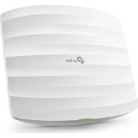
Omada EAP223 - Access Point TP-LINK - Free user manual and instructions
Find the device manual for free Omada EAP223 TP-LINK in PDF.



| Product Type | Wi-Fi Access Point |
| Brand | TP-Link |
| Model | Omada EAP223 |
| Dimensions (approx.) | 200 x 200 x 30 mm |
| Weight (approx.) | 0.3 kg |
| Power Supply | PoE (802.3af/at) or power adapter (not included) |
| Network Interface | 1 Gigabit Ethernet port (PoE in) |
| Wireless Standards | IEEE 802.11a/b/g/n/ac/ax |
| Frequency Bands | 2.4 GHz and 5 GHz |
| Maximum Theoretical Throughput | Up to 1.8 Gbps |
| Centralized Management | Omada Controller (software or hardware) |
| Installation | Ceiling or wall mounting |
| Maintenance and Cleaning | Clean with a dry, soft cloth. Do not use chemicals. |
| Safety | Follow instructions: avoid water, fire, do not disassemble. Use only recommended accessories. |
| Spare Parts and Repairability | Not available. Contact TP-Link support for any issues. |
Frequently Asked Questions - Omada EAP223 TP-LINK
User questions about Omada EAP223 TP-LINK
0 question about this device. Answer the ones you know or ask your own.
Ask a new question about this device
Download the instructions for your Access Point in PDF format for free! Find your manual Omada EAP223 - TP-LINK and take your electronic device back in hand. On this page are published all the documents necessary for the use of your device. Omada EAP223 by TP-LINK.
USER MANUAL Omada EAP223 TP-LINK
Hardwareinstallation
■ Option 1: Deckenmontage
2
■ Option 2: Wandmontage
Spannungsversorgung
Note: Images may differ from your actual product
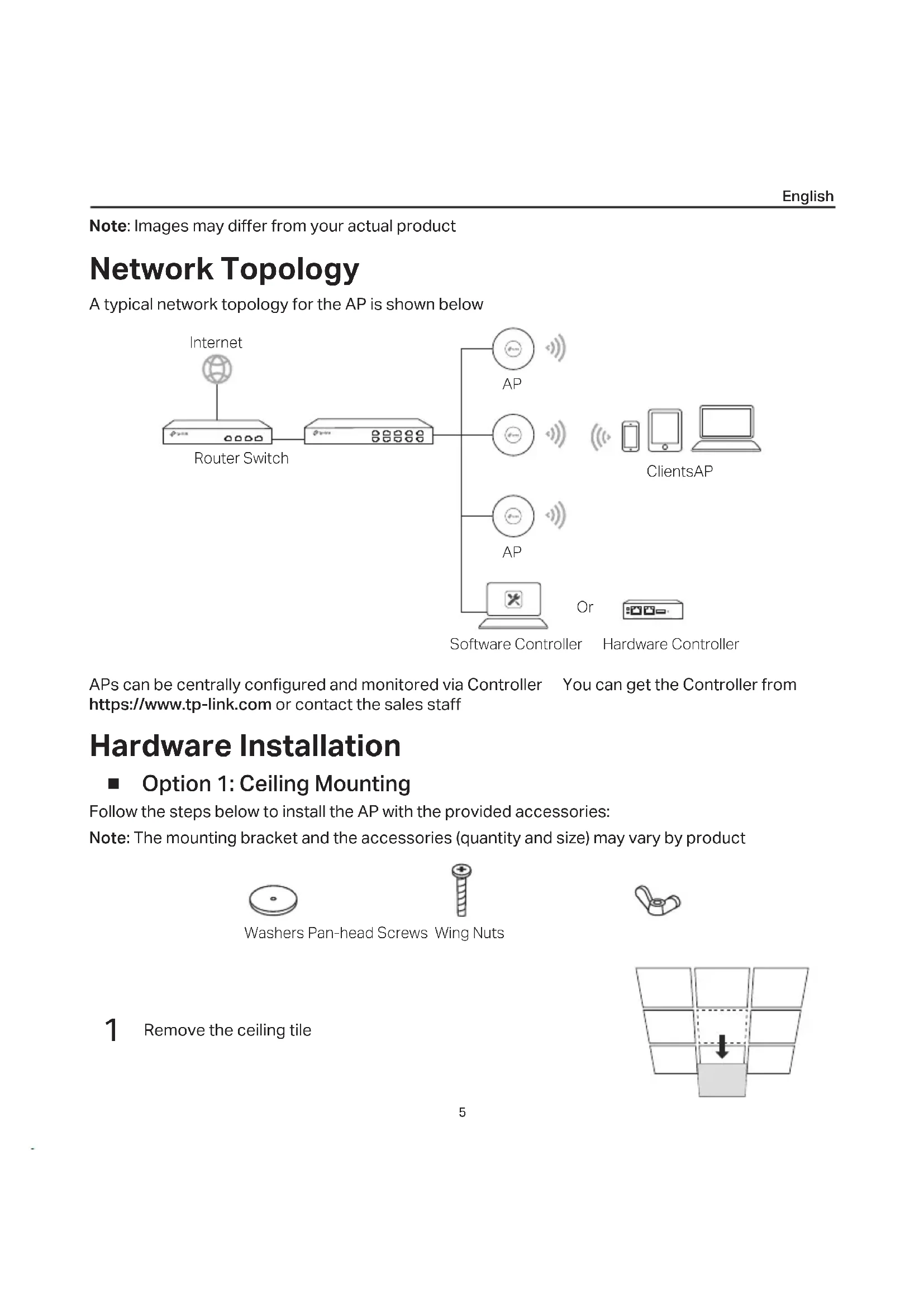
Network Topology
A typical network topology for the AP is shown below
![graph LR A["Internet"] --> B["Router Switch"] B --> C["AP"] B --> D["AP"] B --> E["AP"] C --> F["Software Controller"] D --> G["Hardware Controller"] E --> H["Hardware Controller"] style A fill:#f9f,stroke:#333 style B fill:#ccf,stroke:#333 style C fill:#cfc,stroke:#333 style D fill:#cfc,stroke:#333…](/content/2026/04/607648/images/bc79c793b5d47b684bd9b13203d6d133ea8d6b44b6e25b0444e0c3c4893012ee.jpg)
APs can be centrally configured and monitored via Controller You can get the Controller from https://www.tp-link.com or contact the sales staff
Hardware Installation
■ Option 1: Ceiling Mounting
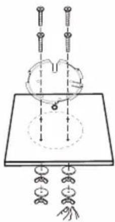
Follow the steps below to install the AP with the provided accessories:
Note: The mounting bracket and the accessories (quantity and size) may vary by product

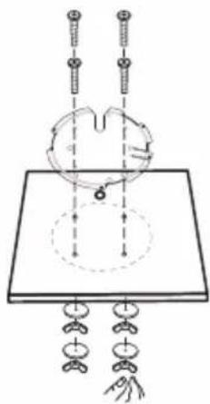
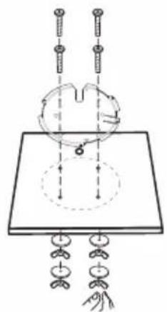
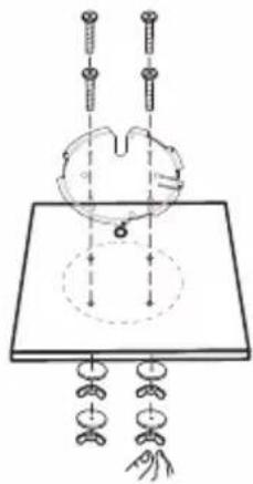
Washers Pan-head Screws Wing Nuts
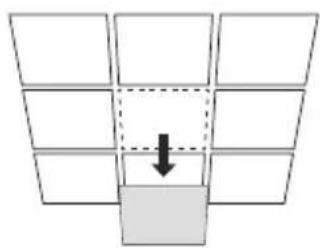
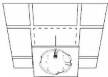
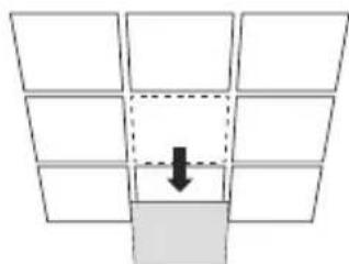
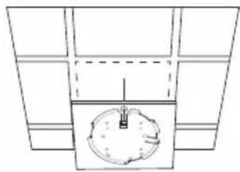
1 Remove the ceiling tile
English
2
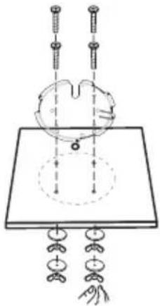
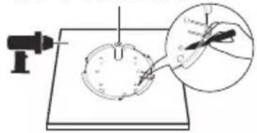
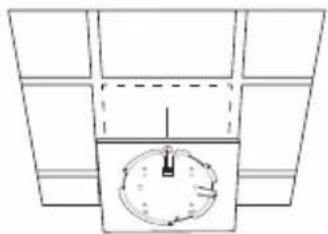
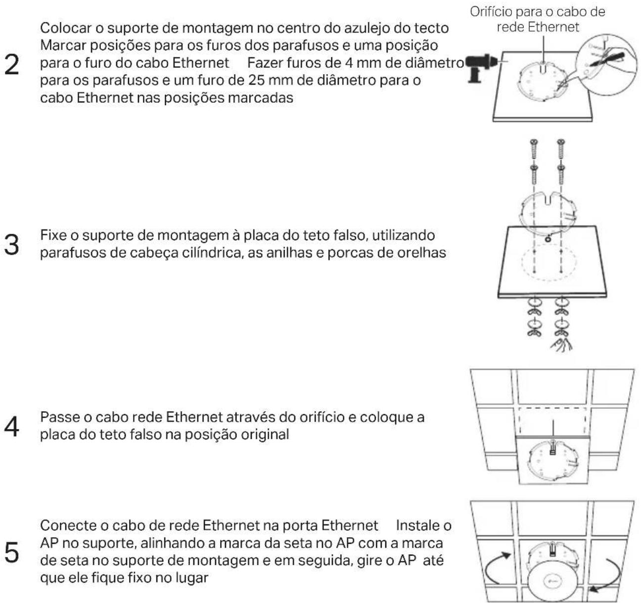
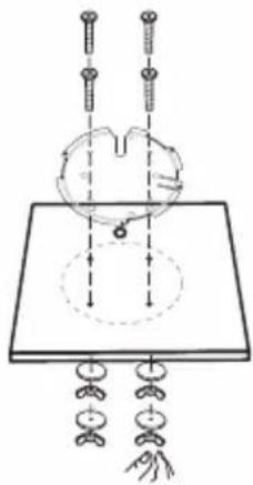
Place the mounting bracket in the center of the ceiling tile Mark positions for the screw holes and a position for the Ethernet cable hole Drill 4 mm diameter holes for the screws and a 25 mm diameter hole for the Ethernet cable at the marked positions
3
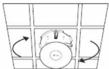
Secure the mounting bracket to the ceiling tile using pan-head screws, washers and wing nuts
4
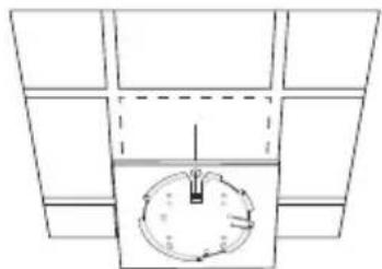
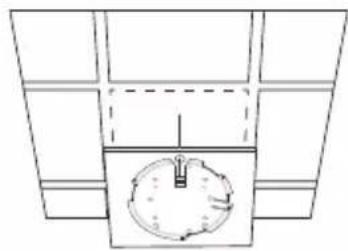
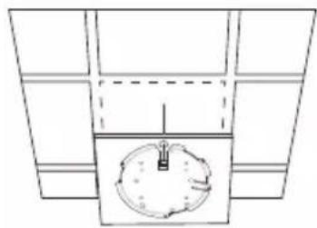
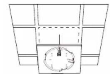
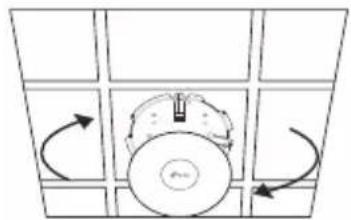
Feed the Ethernet cable through the hole and set the ceiling tile back into place
5
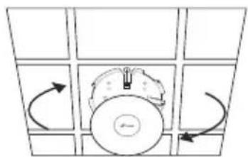
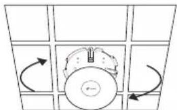
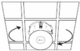
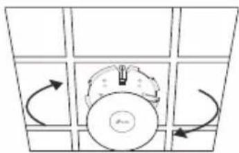
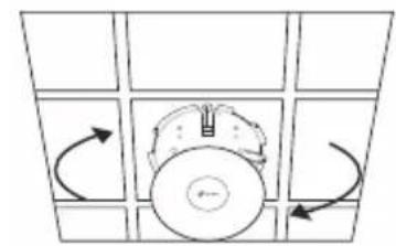
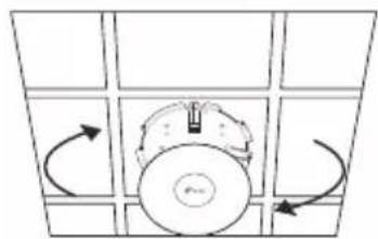
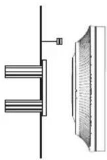
Connect the Ethernet cable to the Ethernet port Attach the AP to the mounting bracket by aligning the arrow mark on the AP with the arrow mark on the mounting bracket, then rotate the AP until it is locked into place
Hole for Ethernet cable
■ Option 2: Wall Mounting
Follow the steps below to install the AP with the provided accessories:
Note: The mounting bracket and the accessories (quantity and size) may vary by product
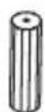
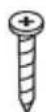
Plastic Wall Anchors Self-tapping Screws
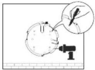
If your Ethernet cable feeds through the wall, position the mounting bracket and feed the Ethernet cable Mark positions for the screw holes and then drill 6 mm diameter holes at the marked positions
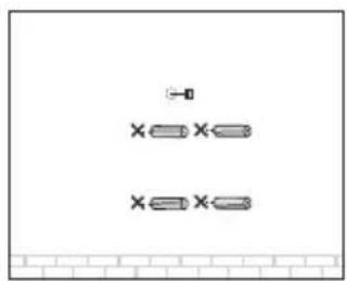
2 Insert the plastic wall anchors into the 6 mm diameter holes
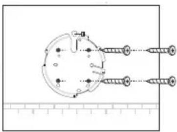
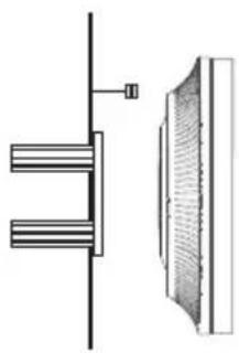
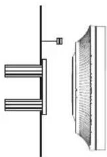
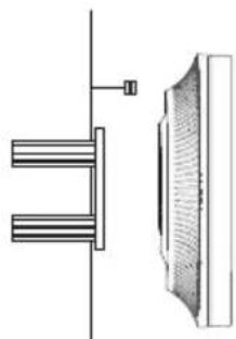
3 Secure the mounting bracket to the wall by driving the self-tapping screws into the anchors Make sure that the shoulders of the mounting bracket are on the outside
4 Connect the Ethernet cable to the Ethernet port on the AP
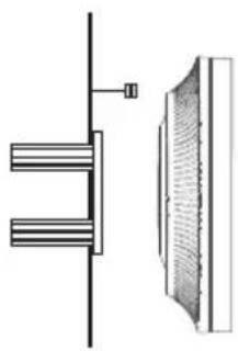
5 Attach the AP to the mounting bracket by aligning the arrow mark on the AP with the arrow mark on the mounting bracket, then rotate the AP until it is locked into place
![graph TD A["Top Center"] --> B["Bottom Center"] B --> C["Top Right"] C --> A](/content/2026/04/607648/images/495e337ac45f49b1244b89dcb81d75cd416b1af96cbcfb888feaa02b630f51e4.jpg)
Power Supply
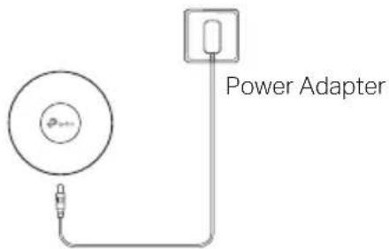
■ Power via PSE Device or Power Adapter
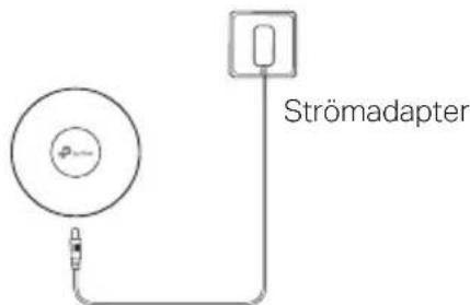
Some APs can be powered via the power adapter or the PSE device (such as a PoE switch) which complies with Power Source Class 2 (PS2) or Limited Power Source (LPS) of IEC 62368-1
Note: Availability depends on the actual product Please refer to the product specifications
Via PoE Switch
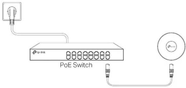
Via Power Adapter
■ Power via PoE Adapter
Some APs can be powered via the PoE adapter
Note: Availability depends on the actual product
Please refer to the product specifications
![graph TD A["Power Source"] --> B["PoE Adapter Switch"] B --> C["Network Port 1"] B --> D["Network Port 2"] B --> E["Network Port 3"] B --> F["Network Port 4"] B --> G["Network Port 5"] B --> H["Network Port 6"] B --> I["Network Port 7"] B --> J["Network Port 8"]](/content/2026/04/607648/images/9f3920e0cb983813b12a66b403c58c6701bc0f1950f5813e18036166a081dfd8.jpg)
2
4 Conecte el cable Ethernet al puerto ETHERNET en el AP
2
2
3
4
5
Rondelles Vis CHC Écrous papillon

2
3
4
5
2
3
4
5
Alimentazione
4 Conecte o cabo de rede Ethernet na porta de rede Ethernet
2

■ Optie 2: Plafondmontage
Via strömadapter
■ Ström via PoE-adapter
Vissa AP:er kan drivas via PoE-adaptern
2
■ Alternativ 2: Montering på vegg
4 Koble Ethernet-kabelen til Ethernet-porten på AP
Strømforsyning
■ Strøm via PoE-adapter
Noen AP-er kan drives via PoE-adapteren
Dansk
2
4 Forbind Ethernet-kablet til ETHERNET-porten på AP
■ Strøm via PoE-adapter
Nogle AP'er kan forsynes med strøm via PoE-adapteren
- Keep the device away from water, fire, humidity or hot environments
- Do not attempt to disassemble, repair, or modify the device If you need service, please contact us
- Do not use damaged charger or USB cable to charge the device
- Do not use any other chargers than those recommended
- Do not use the device where wireless devices are not allowed
- Adapter shall be installed near the equipment and shall be easily accessible
Please read and follow the above safety information when operating the device guarantee that no accidents or damage will occur due to improper use of device product with care and operate at your own risk We cannot Please use this
Español
TP-Link hereby declares that the device is in compliance with the essential requirements and other relevant provisions of directives (EU)2015/863, 2014/53/EU, 2009/125/EC and 2011/65/EU. The original EU declaration of conformity may be found at https://www.tp-link.com/support/ce/
Español
https://www.tp-link.com/support/ce/
Italiano
https://www.tp-link.com/support/ce/
Nederlands
https://www.tp-link.com/support/ce/
Svenska
https://www.tp-link.com/support/ce/
Norsk
TP-Link erklærer herved at denne enheten er i samsvar med de nødvendige kravene og andre relevante bestemmelser fra direktivene (EU)2015/863, 2014/53/EU, 2009/125/EC og 2011/65/EU.
https://www.tp-link.com/support/ce/
Dansk
For TP-Link Branded Products Only For the information about warranty period, policy and procedures, please visit https://www.tp-link.com/en/support
THIS WARRANTY GIVES YOU SPECIFIC LEGAL RIGHTS, AND YOU MAY HAVE OTHER RIGHTS THAT VARY FROM STATE TO STATE (OR BY COUNTRY OR PROVINCE)
TO THE EXTENT ALLOWED BY LOCAL LAW, THIS WARRANTY AND THE REMEDIES SET FORTH ARE EXCLUSIVE AND IN LIEU OF ALL OTHER WARRANTIES, REMEDIES AND CONDITIONS
TP-Link warrants the TP-Link branded hardware product contained in the original packaging against defects in materials and workmanship when used normally in according with TP-Link's guidelines for some period which depends on the local service from the date of original retail purchase by the end-user purchaser
Español
For technical support, the user guide and other information, please visit https://www.tp-link.com/support/, or simply scan the QR code.


- HARDWAREINSTALLATION
- OPTION 1: DECKENMONTAGE
- 2
- OPTION 2: WANDMONTAGE
- SPANNUNGSVERSORGUNG
- NETWORK TOPOLOGY
- HARDWARE INSTALLATION
- OPTION 1: CEILING MOUNTING
- ENGLISH
- 3
- 4
- 5
- OPTION 2: WALL MOUNTING
- POWER SUPPLY
- POWER VIA PSE DEVICE OR POWER ADAPTER
- VIA POE SWITCH
- VIA POWER ADAPTER
- POWER VIA POE ADAPTER
- ALIMENTAZIONE
- OPTIE 2: PLAFONDMONTAGE
- VIA STRÖMADAPTER
- STRÖM VIA POE-ADAPTER
- ALTERNATIV 2: MONTERING PÅ VEGG
- STRØMFORSYNING
- STRØM VIA POE-ADAPTER
- DANSK
- ESPAÑOL
- ITALIANO
- NEDERLANDS
- SVENSKA
- NORSK
Brand : TP-LINK
Model : Omada EAP223
Category : Access Point