HandyLaser Plus - Laser pointer Laserliner - Free user manual and instructions
Find the device manual for free HandyLaser Plus Laserliner in PDF.


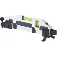
| Product type | Universal laser bubble level |
| Brand | Laserliner |
| Model | HandyLaser Plus |
| Dimensions (L x H x D) | 210 x 59 x 62 mm |
| Weight (batteries included) | 130 g |
| Power supply | 2 x 1.5V LR03 (AAA) batteries |
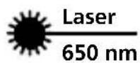
| Laser class | 2 / < 1 mW (EN 60825-1:2014/AC:2017) |
| Laser wavelength | 650 nm |
| Working range (depending on brightness) | 50 m |
| Bubble accuracy | ± 0.5 mm/m |
| Operating conditions | 0°C ... 50°C, max. 80% RH, non-condensing |
| Storage conditions | -10°C ... 70°C, max. 80% RH |
| Main functions | Horizontal and vertical leveling, laser alignment for tiling, magnetic and spring clamp fixation |
| Maintenance and cleaning | Clean with a slightly damp cloth, avoid abrasive products or solvents. Remove batteries before prolonged storage. |
| Safety | Do not look directly into the beam. Keep out of reach of children. Maintain distances from magnetic fields (≥20 cm from implants). |
| Spare parts and repairability | Not specified in the manual. Contact Laserliner after-sales service. |
| General information | Impact-resistant housing with rubber edges. Automatic shut-off not mentioned. Batteries not included. |
Frequently Asked Questions - HandyLaser Plus Laserliner
User questions about HandyLaser Plus Laserliner
0 question about this device. Answer the ones you know or ask your own.
Ask a new question about this device
Download the instructions for your Laser pointer in PDF format for free! Find your manual HandyLaser Plus - Laserliner and take your electronic device back in hand. On this page are published all the documents necessary for the use of your device. HandyLaser Plus by Laserliner.
USER MANUAL HandyLaser Plus Laserliner
natural_image
3D model of a white and black mechanical component with mounting brackets (no visible text or symbols)| DE 02 |
| EN 06 |
| NL 10 |
| DA 14 |
| FR 18 |
| ES 22 |
| IT 26 |
| PL 30 |
| FI 34 |
| PT 38 |
| SV 42 |
| NO 46 |
| TR |
| RU |
| UK |
| CS |
| ET |
| RO |
| BG |
| EL |
| SL |
| HU |
| SK |
| HR |

magnetic
Laserliner
Laserliner

natural_image
Warning symbol with a triangle and central sunburst pattern (no text)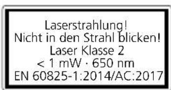
natural_image
Close-up of a battery component with two cylindrical batteries and one external bulb (no visible text or symbols)Laserliner
natural_image
Mechanical component with a downward arrow indicating a specific feature (no text or symbols visible)natural_image
Diagram of a mechanical assembly with directional arrows indicating movement or force (no text or symbols)natural_image
3D diagram of a mechanical device with downward arrows indicating force or movement (no text or symbols)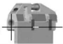
natural_image
Pure mechanical component diagram without any text, numbers, or symbols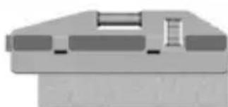
natural_image
Pure mechanical component diagram without any text, numbers, or symbols
natural_image
Two technical diagrams showing mechanical components with no visible text or symbolsCompletely read through the operating instructions, the „Warranty and Additional Information“ booklet as well as the latest information under the internet link at the end of these instructions. Follow the instructions they contain. This document must be kept in a safe place and if the laser device is passed on, this document must be passed on with it.
Universal laser spirit level
- Integrated dot laser for optical extension
- Special spring clips, ideal for tiling
– Free hands when working on metal constructions thanks to magnetic holder - ON/OFF switch with highly visible LED laser indicator
- Impact-proof, plastic casing with rubberised grips
General safety instructions
- The device must only be used in accordance with its intended purpose and within the scope of the specifications.
- The measuring tools and accessories are not toys. Keep out of reach of children.
- Modifications or changes to the device are not permitted, this will otherwise invalidate the approval and safety specifications.
- Do not expose the device to mechanical stress, extreme temperatures, moisture or significant vibration.
- The device must no longer be used if one or more of its functions fail or the battery charge is weak.
Safety instructions
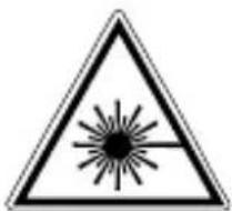
Using class 2 lasers
natural_image
Warning symbol with a triangle and central starburst (no text or numbers)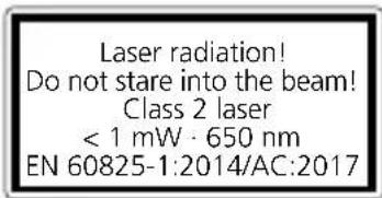
- Attention: Do not look into the direct or reflected beam.
- The laser may not get into the hands of children!
-
Do not point the laser beam towards persons.
-
If a person's eyes are exposed to class 2 laser radiation, they should shut their eyes and immediately move away from the beam.
- Do not expose the device to mechanical stress, extreme temperatures, moisture or significant vibration.
- The device must only be used in accordance with its intended purpose and within the scope of the specifications. Modifications or changes to the device are not permitted, this will otherwise invalidate the approval and safety specifications.
Safety instructions
Dealing with electromagnetic radiation
- The measuring device complies with electromagnetic compatibility regulations and limits in accordance with the EMC Directive 2014/30/EU.
- Local operating restrictions – for example, in hospitals, aircraft, petrol stations or in the vicinity of people with pacemakers – may apply. Electronic devices can potentially cause hazards or interference or be subject to hazards or interference.
Danger – powerful magnetic fields
Powerful magnetic fields can adversely affect persons with active medical implants (e.g. pacemaker) as well as electromechanical devices (e.g. magnetic cards, mechanical clocks, precision mechanics, hard disks).
With regard to the effect of powerful magnetic fields on persons, the applicable national stipulations and regulations must be complied with such as BGV B11 §14 „electromagnetic fields" (occupational health and safety - electromagnetic fields) in the Federal Republic of Germany.
To avoid interference/disruption, always keep the implant or device a safe distance of at least 30 cm away from the magnet.
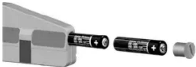
1 Inserting batteries
Open the battery compartment and insert batteries according to the symbols. Be sure to pay attention to polarity.
natural_image
Close-up of a battery with two charging ends and a separate cylindrical component (no visible text or symbols)Laserliner
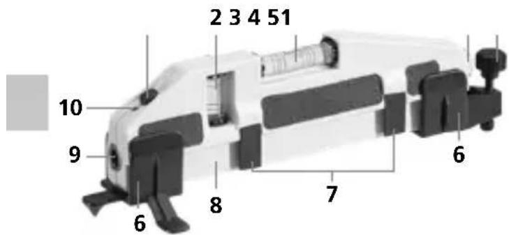
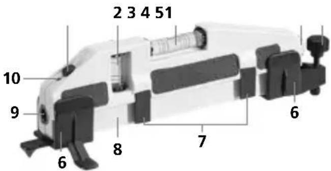
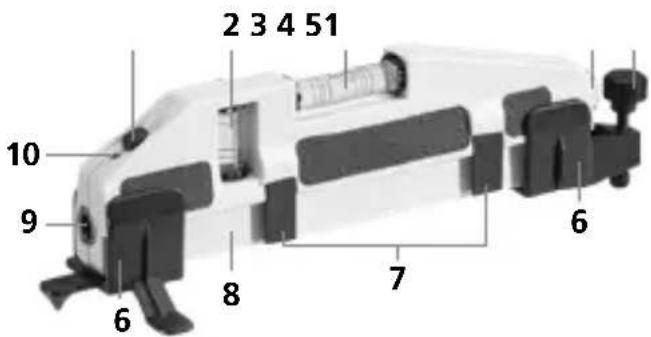
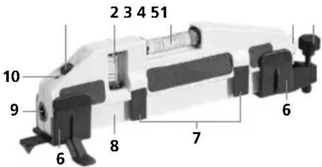
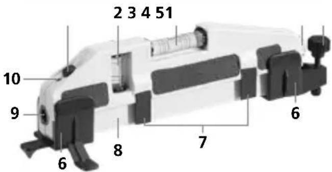
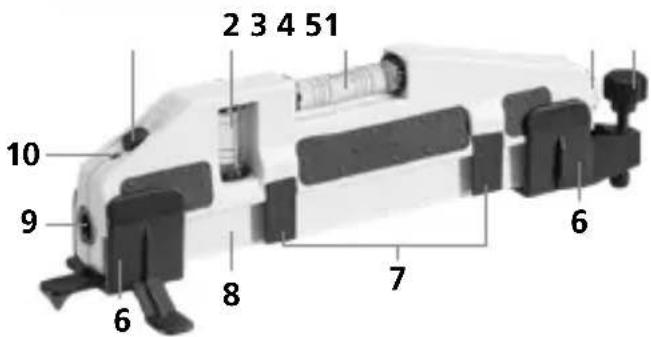
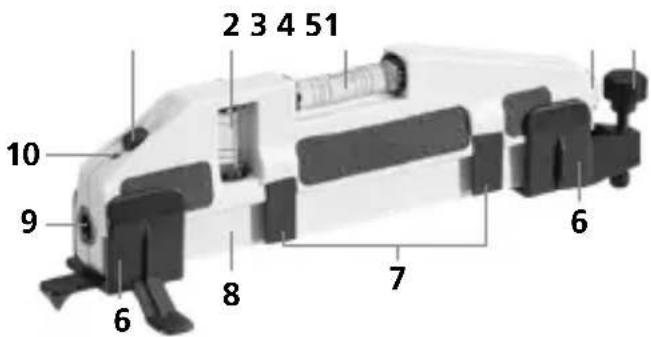
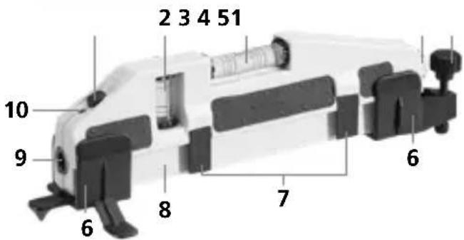
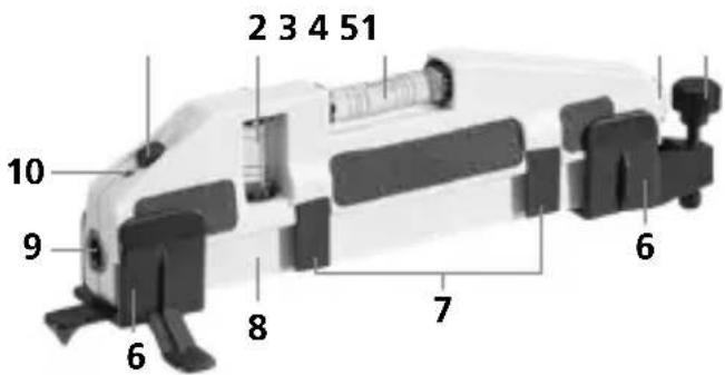
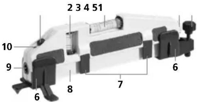
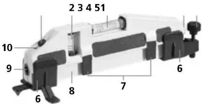
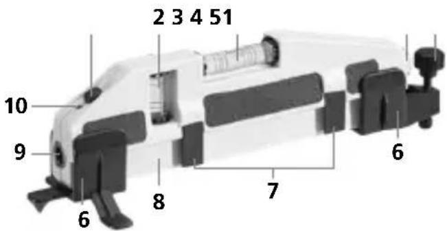
1 ON/OFF switch
2 Vertical vial
3 Horizontal vial
4 Battery compartment
5 Levelling foot adjustment
6 Levelling foot
7 Spring-clamp holder
8 Magnets (bottom)
9 Laser output windows
10 LED laser indicator
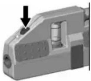
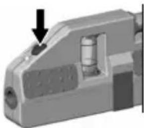
2 ON/OFF
natural_image
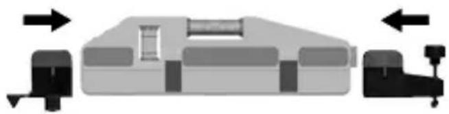
3D mechanical component with a black arrow pointing to a small cylindrical feature (no text or symbols visible)3 Attaching adjustable legs
natural_image
Diagram of a mechanical component with directional arrows indicating movement or force (no text or symbols)4 To fit wall tiles
natural_image
3D diagram of a mechanical component with downward arrows indicating force or movement (no text or symbols)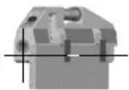
natural_image
Pure mechanical component diagram without any text, numbers, or symbols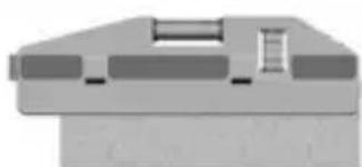
natural_image
Pure mechanical component diagram without any text, numbers, or symbols
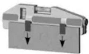
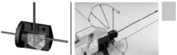
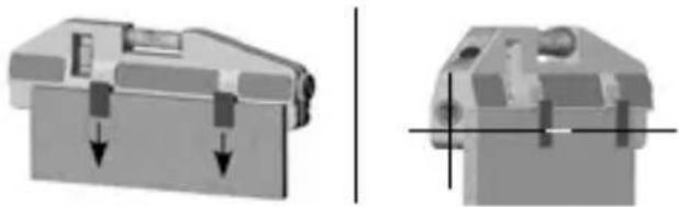
To fit wall tiles, the device is attached to the first tile by means of the spring-clamp holder that is pushed out with the pins at the rear. The laser beam that runs parallel to the horizontal spirit level is directed along the edge of the tile. This makes it possible to precisely align the tile with the bubble level.
5 90° beam splitter
(depending on product version)
natural_image
Mechanical assembly diagram showing a cylindrical component and a truck-mounted device with directional arrows (no text or symbols)The 90° beam splitter allows the laser beam to be additionally deflected by 90°.
Information on maintenance and care
Clean all components with a damp cloth and do not use cleaning agents, scouring agents and solvents. Remove the battery(ies) before storing for longer periods. Store the device in a clean and dry place.
Technische Daten
| Vial accuracy ± 0.5 mm / m | |
| Operating range | (depending on room illumination) 50 m |
| Laser wavelength | 650 nm |
| Laser class | 2 / < 1 mW (EN 60825-1:2014/AC:2017) |
| Power supply | 2 x 1.5V LR03 (AAA) |
| Operating conditions | 0°C ... 50°C, max. humidity 80% rH, no condensation, max. working altitude 4000 m above sea level |
| Storage conditions | -10°C ... 70°C, max. humidity 80% rH |
| Weight | 130 g (incl. batteries) |
| Dimensions (W x H x D) | 210 x 59 x 62 mm |
Subject to technical alterations. 20W44
EU directives and disposal
This device complies with all necessary standards for the free movement of goods within the EU.
This product is an electric device and must be collected separately for disposal according to the European Directive on waste electrical and electronic equipment.
Further safety and supplementary notices at: http://laserliner.com/info?an=ACQ
Laserliner

natural_image
Close-up of a battery component with two cylindrical batteries and one external bulb (no visible text or symbols)Laserliner
natural_image
Mechanical component with a black arrow pointing to a specific part (no visible text or symbols)natural_image
Diagram of a mechanical assembly with directional arrows indicating movement or force (no text or symbols)natural_image
3D diagram of a mechanical device with downward arrows indicating force or movement (no text or symbols)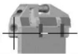
natural_image
Pure mechanical component diagram without any text, numbers, or symbols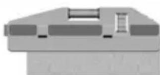
natural_image
Pure mechanical component diagram without any text, numbers, or symbols
natural_image
Two technical diagrams showing a mechanical component and its assembly with rotating blades (no text or symbols)natural_image
Close-up of a battery component with two cylindrical batteries and one terminal, showing internal structure (no text or symbols visible)Laserliner
natural_image
Mechanical component with a black arrow pointing to a specific part (no visible text or symbols)natural_image
Diagram of a mechanical assembly with directional arrows indicating movement or force (no text or symbols)natural_image
3D diagram of a mechanical device with downward arrows indicating force or movement (no text or symbols)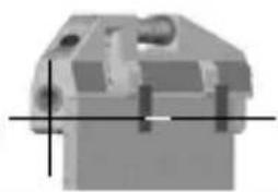
natural_image
Pure mechanical component diagram without any text, numbers, or symbols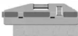
natural_image
Pure mechanical component diagram without any text, numbers, or symbols
natural_image
Two technical diagrams showing mechanical components with no visible text or symbolsnatural_image
Close-up of a battery component with two cylindrical batteries and a separate terminal, no visible text or symbols.Laserliner
natural_image
Mechanical component with a downward arrow indicating a specific feature (no text or symbols visible)natural_image
Diagram of a mechanical assembly with directional arrows indicating movement or force (no text or symbols)natural_image
Mechanical component with downward arrows indicating force or movement (no text or symbols)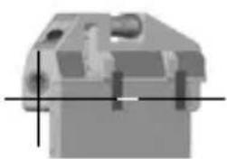
natural_image
3D rendered mechanical part with crosshair alignment lines (no text or symbols)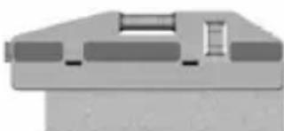
natural_image
Pure mechanical component diagram without any text, numbers, or symbols
natural_image
Mechanical assembly diagram showing a cylindrical component and a motor with rotating blades (no text or symbols)natural_image
Close-up of a battery component with two cylindrical batteries and a separate cylindrical pin (no visible text or symbols)Laserliner
natural_image
Mechanical component with a black arrow pointing to a small cylindrical feature (no text or symbols visible)natural_image
Diagram of a mechanical device with directional arrows indicating movement or force (no text or symbols)natural_image
Two technical diagrams showing mechanical components with downward arrows indicating force or movement (no text or symbols present)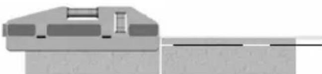
natural_image
Pure mechanical component diagram without any text, numbers, or symbolsnatural_image
Mechanical assembly diagram showing a cylindrical component and a motor with rotating blades (no text or symbols)natural_image
Close-up of a battery component with two cylindrical batteries and a terminal pin, no visible text or symbols.Laserliner
natural_image
Mechanical component with a downward arrow indicating a specific feature (no text or symbols visible)natural_image
Diagram of a mechanical assembly with directional arrows indicating movement or force (no text or symbols)natural_image
3D diagram of a mechanical component with downward arrows indicating force or movement (no text or symbols)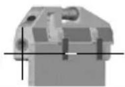
natural_image
Pure mechanical component diagram without any text, numbers, or symbols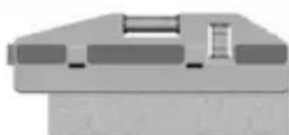
natural_image
Pure mechanical component diagram without any text, numbers, or symbols
natural_image
Mechanical assembly diagram showing a cylindrical component and a motor with rotating blades (no text or symbols)natural_image
Close-up of a battery component with two cylindrical batteries and a terminal connector (no visible text or symbols)Laserliner
natural_image
Mechanical component with a cylindrical part inserted, showing a downward arrow (no text or symbols visible)natural_image
Diagram of a mechanical component with directional arrows indicating movement or force (no text or symbols)natural_image
Mechanical component with downward arrows indicating force or movement (no text or symbols)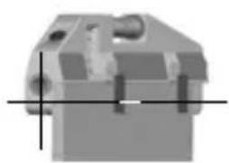
natural_image
3D mechanical part with crosshair alignment lines (no text or symbols)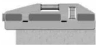
natural_image
Pure mechanical component diagram without any text, numbers, or symbols
natural_image
Mechanical assembly diagram showing a cylindrical component and a motor with rotating blades (no text or symbols)natural_image
Illustration of a battery with two different sizes and polarity markings (no text or symbols)Laserliner
1 PÄÄLLE/POIS-kytkin
2 Pystylibelli
3 Vaakalibelli
4 Paristolokero
5 Tasausjalan säätö
6 Tasausjalka
natural_image
3D mechanical component with a black arrow pointing to a small cylindrical feature (no text or symbols visible)natural_image
Diagram of a mechanical component with directional arrows indicating movement or force (no text or symbols)natural_image
3D diagram of a mechanical device with downward arrows indicating force or movement (no text or symbols)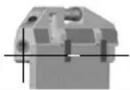
natural_image
Pure mechanical component outline without any text, numbers, or symbols
natural_image
Pure mechanical component diagram without any text, numbers, or symbols
natural_image
Mechanical assembly diagram showing a cylindrical component and a motor with rotating blades (no text or symbols)natural_image
Warning symbol with a triangular triangle and central sunburst pattern (no text)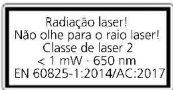
natural_image
Close-up of a battery component with two cylindrical batteries and one external bulb (no visible text or symbols)Laserliner
natural_image
Mechanical component with a downward arrow indicating a feature (no visible text or symbols)natural_image
Diagram of a mechanical component with directional arrows indicating movement or force (no text or symbols)4 Assentar azulejos de parede
natural_image
Two technical diagrams showing mechanical components with downward arrows indicating force or movement (no text or symbols present)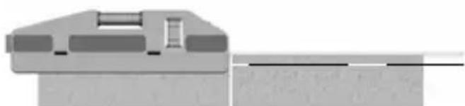
natural_image
Pure mechanical component diagram without any text, numbers, or symbolsnatural_image
Mechanical assembly diagram showing a cylindrical component and a motor with rotating blades (no text or symbols)natural_image
Warning symbol with a triangle and central sunburst pattern (no text)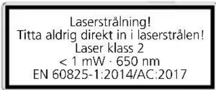
natural_image
Close-up of a battery component with two cylindrical batteries and one external bulb (no visible text or symbols)Laserliner
1 PÅ- / AV-knapp
6 Justerfot
2 Vertikal libell
7 Fjäderklämfäste
natural_image
Mechanical component with a downward arrow indicating a feature (no visible text or symbols)natural_image
Diagram of a mechanical component with directional arrows indicating movement or force (no text or symbols)natural_image
Two mechanical component diagrams showing internal features with downward arrows, no text or symbols present.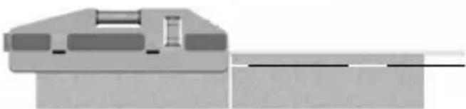
natural_image
Pure mechanical component diagram without any text, numbers, or symbolsnatural_image
Two technical diagrams showing mechanical components with no visible text or symbolsnatural_image
Warning symbol with a triangle and central starburst (no text or numbers)
natural_image
Close-up of a battery with two external components and a separate cylindrical component (no visible text or symbols)Laserliner
1 PÅ- / AV bryter
2 Vertikalt vaterpass
3 Horisontalt vaterpass
4 Batterirom
5 Innstilling
justeringsfot
6 Justeringsfot
7 Fjær-klemmeholder
8 Magneter (underside)
9 Laserstrålehull
10 LED laserindikator
2 ON/OFF
natural_image
Mechanical component with a downward arrow indicating a specific feature (no text or symbols visible)natural_image
Diagram of a mechanical component with directional arrows indicating movement or force (no text or symbols)natural_image
3D diagram of a mechanical component with downward arrows indicating force or movement (no text or symbols)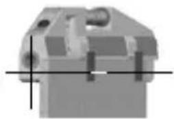
natural_image
Pure mechanical component diagram without any text, numbers, or symbols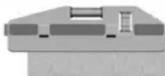
natural_image
Pure mechanical component diagram without any text, numbers, or symbols
natural_image
Mechanical assembly diagram showing a cylindrical component and a motor with rotating blades (no text or symbols)Med den 90° stråledeleren kan man styre om laserstrålen 90°.
natural_image
Isometric illustration of an industrial facility with pipes and a conveyor system, set on a grid-patterned floor (no text or symbols)Rev20W44

SERVICE
Umarex GmbH & Co. KG
- Laserliner -
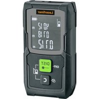

- Laserliner
- Universal laser spirit level
- General safety instructions
- Safety instructions
- Danger – powerful magnetic fields
- Inserting batteries
- ON/OFF
- Attaching adjustable legs
- To fit wall tiles
- 90° beam splitter
- Information on maintenance and care
- EU directives and disposal
- Assentar azulejos de parede
- SERVICE
- Umarex GmbH & Co. KG
Brand : Laserliner
Model : HandyLaser Plus
Category : Laser pointer