ST 710 - Measuring equipment BENNING - Free user manual and instructions
Find the device manual for free ST 710 BENNING in PDF.

| Product Type | Appliance Controller (Electrical Safety Tester) |
| Brand | BENNING |
| Model | ST 710 |
| Power Supply | 6 LR6/AA batteries (1.5 V) |
| Display | LCD |
| Application Area | Safety testing according to EN 50678 and EN 50699 |
| Measurements | Protective conductor resistance (RPE), insulation resistance (RISO), equivalent leakage current (IEA), line test, voltage measurement |
| RPE Range | 0.05 Ω - 20 Ω |
| RISO Range | 0.1 MΩ - 20 MΩ |
| IEA Range | 0.10 mA - 20 mA |
| RISO Test Voltage | 500 VDC |
| Overvoltage Category | 300 V category II |
| Pollution Degree | 2 |
| Protection Rating | IP40 |
| Operating Temperature | 0°C to 40°C |
| Storage Temperature | -25°C to +65°C |
| Supplied Accessories | Test lead with alligator clip, IEC power cord, compact case, 6 batteries |
| Optional Accessories | Three-phase adapter, BENNING CM 9-1/9-2 leakage current clamp |
| Maintenance | Clean with a dry cloth, do not open, replace batteries if necessary |
| Standards | DIN EN 61010-1, DIN EN 61557-1,2,4,10,16 |
Frequently Asked Questions - ST 710 BENNING
User questions about ST 710 BENNING
0 question about this device. Answer the ones you know or ask your own.
Ask a new question about this device
Download the instructions for your Measuring equipment in PDF format for free! Find your manual ST 710 - BENNING and take your electronic device back in hand. On this page are published all the documents necessary for the use of your device. ST 710 by BENNING.
USER MANUAL ST 710 BENNING
Switch on test object during test

BENNING

Operating manual BENNING ST 710 with Swiss plug system and firmware (item no. 050315) at

Fig. 4: Testing of devices of protection class II (shockproof devices without protective conductor and with accessible conductive parts) and testing of devices of protection class III (safety extra-low voltage)
Fig. 5b: Testing of lines, multiple distributors and cable reels
Appliance tester for safety-related testing of portable electrical devices and equipment
- testing according to EN 50678 and EN 50699
- testing of cable reels, multiple distributors and IEC power cords
- voltage measurement on external shock-proof socket
Table of contents
- User notes
- Safety note
- Scope of delivery
- Unit description
- General information
- Ambient conditions
- Electrical specifications
- Measuring with the BENNING ST 710
- Maintenance
- Environmental note
1. User notes
These operating instructions are intended for
- qualified electricians, competent persons and
- electrotechnically trained persons
The BENNING ST 710 is intended for making measurements in dry environment. It must not be used in power circuits with a nominal voltage higher than 300V AC (More details in Section 6. "Ambient conditions").
The following symbols are used in these operating instructions and on the BENNING ST 710:

Application around and removal from HAZARDOUS LIVE conductors is permitted.

Warning of electrical danger!
Indicates instructions which must be followed to avoid danger to persons.

Important, comply with the documentation! The symbol indicates that the information provided in the operating instructions must be complied with in order to avoid risks.

This symbol on the BENNING ST 710 means that the BENNING ST 710 is totally insulated (protection class II).

This symbol on the BENNING ST 710 means that the BENNING ST 710 complies with the EU directives.

This symbol appears on the display to indicate a discharged battery.

(AC) Alternating voltage or current.

Ground (Voltage against ground).
2. Safety note
The instrument is built and tested in accordance with
DIN EN 61010 part 1 (VDE 0411 part 1)
DIN EN 61557 part 1, 2, 4, 10 and 16 (VDE 0413 part 1, 2, 4, 10 and 16)
and has left the factory in perfectly safe technical state.
To maintain this state and ensure safe operation of the appliance tester, the user must observe the notes and warnings given in these instructions at all times. Improper handling and non-observation of the warnings might involve severe injuries or danger to life.

WARNING! Be careful when working with bare conductors or main line carrier! Contact with live conductors will cause an electric shock!

The BENNING ST 710 may be used only in power circuits within the overvoltage category II with a conductor for 300 V AC max. to earth.
Remember that work on electrical components of all kinds is dangerous. Even low voltages of 30 V AC and 60 V DC may be dangerous to human life.

Before starting the appliance tester up, always check it for signs of damage.
Should it appear that safe operation of the appliance tester is no longer possible, it should be shut down immediately and secured to prevent it being switched on accidentally.
It may be assumed that safe operation is no longer possible:
- if the instrument show visible signs of damage
- if the appliance tester no longer functions
- after long periods of storage under unfavourable conditions
- after being subjected to rough transport
- the device is exposed to moisture.

In order to prevent danger
- do not touch the bare measuring probe tips of the measuring leads,
- plug the leads into the correspondingly marked jacks at the measuring

Maintenance:
Do not open the tester, because it contains no components which can be
repaired by the user. Repair and service must be carried out by qualified
personnel only!

Cleaning:
Regularly wipe the housing by means of a dry cloth and cleaning agent. Do not
use any polishing agents or solvents!
3. Scope of delivery
The scope of delivery for the BENNING ST 710 comprises:
3.1 One BENNING ST 710
3.2 One test lead with alligator clip (10024456),
3.3 One IEC power cord (IEC adapter calbe) (10009127),
3.4 One compact protective pouch (10024452),
3.5 Six 1.5-V-batteries/ type AA (IEC LR6) fitted in the unit as initial equipment,
3.4 One operating manual
Parts subject to wear:
- The BENNING ST 710 is supplied by six 1.5V batteries/ type AA (IEC LR6).
Note on optional accessories:
-
Test badges "next test date", 300 pieces
-
Measuring adapter for three-phase loads
for R PE, RISO (insulating resistance) and IEA (alternative leakage current) measurements:
- 16 A CEE coupling - 16 A shock-proof plug (044122)
- 32 A CEE coupling - 16 A shock-proof plug (044123)
As an alternative:
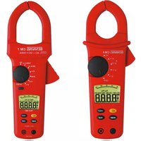
- BENNING CM 9-1 (044682) leakage current clamp or BENNING CM 9-2 (044685) leakage current clamp for measuring the differential current, protective conductor current and load current of single-phase and three-phase loads
- Measuring adapter for BENNING CM 9-1 (044682) leakage current clamp or BENNING CM 9-2 (044685) leakage current clamp, conductors led through individually, with double insulation:
-
16 A shock-proof coupling - 16 A shock-proof plug (044131)
-
16 A CEE coupling - CEE plug (044127)
- 32 A CEE coupling - CEE plug (044128)
- Test certificate forms for "Testing of electrical devices" are available for download free of charge at www.benning.de
4. Unit description
See figure 1: Appliance front face
See figure 2: Top side of the device
The display and operator control elements specified in Fig. 1 and 2 are designated as follows:
1 test socket, for connecting the device to be tested.
2 -key, testing of devices of protection class I (devices with protective conductor and accessible conductive parts which are connected to the protective conductor),
3 symbol key, testing of devices of protection class II (shock-proof devices without protective conductor and with accessible conductive parts) and testing of devices of protection class III (safety extra-low voltage),
4 -symbol key, testing of lines, multiple distributors and device connecting cables with IEC connector
LC display, indicates the test progress and individual measuring results,
4 mm test socket, for connecting the test lead with alligator clip
IEC connector, for connecting the IEC power cord
5. General information
The BENNING ST 710 is intended for electrical safety tests according to EN 50678 and EN 50699.
Automatically, the BENNING ST 710 verifies the type of the connected test object and informs the user in case of incorrect selection of the testing procedure [2...4]: preset limiting values and measuring results with "pass/ fail" information make it easier to evaluate the test.
6. Ambient conditions
- The BENNING ST 710 is intended for making measurements in dry environment.
Maximum barometric elevation for making measurements: 2000m - Over voltage category/ setting category: IEC 61010-1 300 V category II,
- Contamination class: 2.
Protection class: IP 40 (IEC/ EN 60529)
IP 40 means: Protection against access to dangerous parts and protection against solid impurities of a diameter >1 mm, (4 - first index). No protection against water, (0 - second index).
EMC:EN61326-1
- Operating temperatures and relative humidity:
For operating temperatures from 0^ to 30^ : relative humidity less than 80%
For operating temperatures from 31^ to 40^ : relative humidity less than 75%
Storage temperature: The BENNING ST 710 can be stored at any temperature within the range of -25^ to +65^ (relative humidity from 0 to 80% ). The battery should be removed from the instrument for storage.
7. Electrical specifications
Note: The measuring accuracy is specified as the sum of
- a relative fraction of the measured value and
- a number of digits (i.e. counting steps of the last digit).
This specified measuring accuracy is valid for temperatures within the range of 18^ to 28^ and relative humidity lower than 80% .
7.1 Protective conductor resistance:
| Measuring range | Resolution | Measuring accuracy |
| 0.05 Ω - 20 Ω | 0.01 Ω | 5 % ± 2 digits |
| Testing current: | >200 mA (2☐ Ω) | |
| open-circuit voltage: | >4 V nominal | |
7.2 Insulating resistance
| Measuring range | Resolution | Measuring accuracy |
| 0.5 MΩ - 20 MΩ | 0.01 MΩ | 5 % ± 2 digits |
| 0.1 MΩ - 0.49 MΩ | 0.01 MΩ | 10 % ± 2 digits |
| Testing voltage: | 500 VDC @ 1 mA nominal, + 20%, - 0% | |
| Testing current: | >1 mA at 500 kΩ, < 2 mA at 2 kΩ | |
7.3 Protective conductor current and contact current by means of alternative leakage current measurement method
Measuring range Resolution Measuring accuracy
0.10 mA - 20 mA 0.01 mA 5% ± 2 digits
Testing voltage:
40V_AC , 50Hz
Testing current: < 5mA at 2k
7.4 Cord test
- measurement of the protective conductor resistance according to 7.1
- measurement of the insulating resistance according to 7.2
- line break testing of the external conductor (L) and the neutral conductor (N)
- short-circuit testing of the external conductor (L) and the neutral conductor (N)
7.5 Voltage measuring on external shock-proof socket
Measuring range Resolution Measuring accuracy Overload protection
| 50 V - 270 VAC | 1 V | < 5 % of the upper measuring range value | 300 V |
Display:
- voltage between the external conductor (L) and the neutral conductor (N)
- voltage between the external conductor (L) and the ground conductor (PE)
- voltage between the neutral conductor (N) and the ground conductor (PE)
7.6 Limiting values according to EN 50678 and EN 50699
Note:
| Protection class I | Protection class II, III | Line test | |
| Protective conductor resistance RPE | For cords with cross-section ≤ 1.5 mm²: ≤ 0.3 Ω up to a length of 5 m, per further 7.5 m: additional 0.1 Ω, max. 1 Ω, For cords with cross-sections over 1.5 mm² and other cable lengths the calculated ohmic resistance value plus 0.1 Ω transition resistance applies. | ≤ 0.3 Ω (see protection class I) | |
| Insulating resistance RISO | ≥ 1 MΩ ≥ 2 MΩ for proving safe disconnection (transformer) ≥ 0.3 MΩ for devices with heating element | ≥ 2 MΩ (protection class II), ≥ 0,25 MΩ (protection class III), | ≥ 1 MΩ |
| Protective conductor current IEA | ≤ 3.5 mA on conductive parts with PE connection 1 mA/ kW up to 10 mA as the upper limit value, for devices with switched on heating elements and a power consumption of more than 3.5 kW | ||
| Contact current IEA | ≤ 0.5 mA on conductive parts without PE connection | ≤ 0.5 mA on conductive parts without PE connection |
8. Measuring with the BENNING ST 710
8.1 Preparations for measuring
Operate and store the BENNING ST 710 only at the specified storage and operating temperatures conditions. Do not permanently expose the device to sunlight.
- Check rated voltage and rated current details specified on the safety measuring leads.
- Strong sources of interference in the vicinity of the BENNING ST 710 might lead to unstable readings and measuring errors.

Before starting the BENNING ST 710, always check the device, the lines and the test object for damages.

Before starting the test, switch the test object on (mains switch ON).

At the beginning of the test it has to be checked whether the selected testing procedure complies with the protection class of the connected test object.
8.1.1 Switching the BENNING ST 710 ON/ OFF
Press and hold the keys 2 and 3 for approx. 3 seconds to switch the BENNING ST 710 on. 2 acoustic signals confirm that the device is switched on. Press the keys again to switch the device off.
After approx. 3 minutes, the BENNING ST 710 switches off automatically (APO, Auto Power-Off). It switches on again when the keys 2 and 3 are pressed. An acoustic signal indicates that the device has switched off automatically. During voltage measurement on an external shockproof socket, the automatic switch-off is deactivated.
8.1.2 Testing procedure
The BENNING ST 710 is intended for electrical safety tests according to EN 50678 and EN 50699. Please refer to the current version of the standards for detailed information concerning the tests and limiting values.
Automatically, the BENNING ST 710 verifies the type of the connected test object and informs the user in case of incorrect preselection of the testing procedure [2...4]
8.2 Testing of electrical devices / equipment according to EN 50678 and EN 50699

Prior to test, a visual inspection of the test object has to be carried out. In case of possible damages, the test must be stopped.
8.2.1 Testing of devices of protection class I

- Testing of devices with protective conductor and accessible conductive parts which are connected to the protective conductor
- Connect the test object to the test socket ① of the BENNING ST 710.
- Plug the 4 mm safety plug of the test lead with alligator clip into the 4 mm safety socket and establish a connection with a metal part of the test object.
- Switch the test object on.
- Press the key 2 to start the automatic testing procedure.
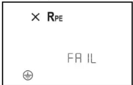
- The test starts with measuring the protective conductor resistance R_PE If R_PE > 100 , the measurement is stopped without a measuring result and a cross is shown next to the R_PE symbol. "FAIL" appears on the display to confirm that the measurement has been stopped.
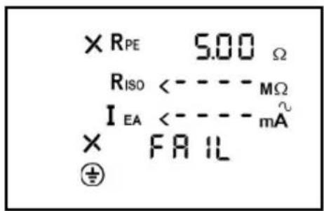
- If R_PE < 20 (but higher than the maximum admissible limiting value), the measured value of R_PE is shown on the display. A next to the R_PE symbol confirms that the limiting value has been exceeded.
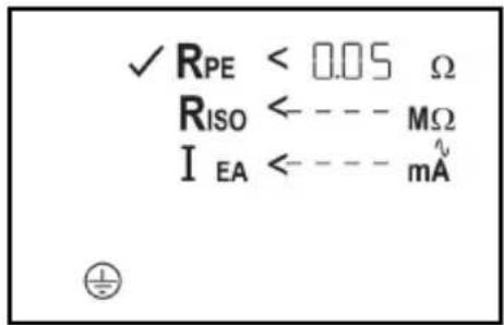
- If R_PE is lower than the admissible limiting value, the measured value of R_PE is shown and a appears next to the R_PE symbol. Now, the R_PE measurement is carried out again with reversed polarity. After the R_PE test has been passed, the test of the insulating resistance is started.
- If "Lo LOAD" is shown on the display, please check whether the test object is switched on.
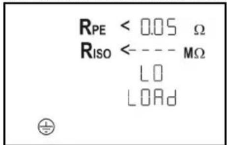
Press the key 2 to continue the testing procedure in case of the load being too low (R_L - N < 100k)
- If the insulating resistance R_ISO is higher than the admissible limiting value, a appears next to the R_ISO symbol.
- Similarly, a is shown next to the I EA symbol, if the protective conductor current I_EA is lower than the admissible limiting value.
- The test is considered to be passed, if "PASS" is shown on the display.
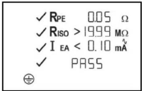
See figure 3: Testing of devices of protection class I (devices with protective conductor and accessible conductive parts which are connected to the protective conductor)
Note on measuring the protective conductor resistance:
- Alternatively, the measurement of the protective conductor resistance R_PE can be carried out as permanent measurement (max. 3 minutes). For this purpose press the key 2 for approx. >5 sec. until the symbol appears on the display. Check the connecting line of the test object by bending it over the entire length in order to detect weak points or a break of the protective conductor. The BENNING ST 710 continuously records the current measured value on the display and stores the maximum value in the memory. By pressing the key 2 again, the measurement is carried out with reversed polarity. Press the key again to indicate the maximum value of R_PE on the display and to continue the testing procedure as described in section 8.2.1.
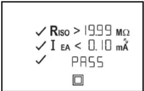
8.2.2 Testing of devices of protection class II (shock-proof) and of devices of protection class III (safety extra-low voltage)
- Testing of devices without protective conductor and with accessible conductive parts
- Connect the test object to the test socket ① of the BENNING ST 710.
- Establish a connection between the 4 mm test socket ③ and a metal part of the test object by means of the test lead with alligator clip.
- Switch the test object on.
- Press the key 3 to start the automatic testing procedure.
- If "Lo LOAD" is shown on the display, please check whether the test object is switched on.
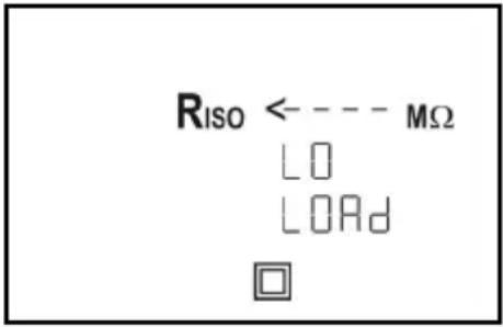
- Press the key ③ to continue the testing procedure in case of the load being too low ( R_L-N > 100 k ).
- If the insulating resistance R_ISO is higher than the admissible limiting value, a appears next to the R_ISO symbol.
- Similarly, a is shown next to the I EA symbol, if the contact current L_EA is lower than the admissible limiting value.
- The test is considered to be passed, if "PASS" is shown on the display.
Note on measuring the insulating resistance for test objects of protection class III:
- Due to the preset limiting value of 2M for test objects of protection class II, for the testing of test objects of protection class III it has to be observed that measured values between the limiting values of 2M (protection class II) and up to 0.25M (protection class III) are indicated with a next to the R ISO symbol.
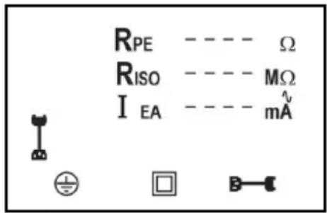
See figure 4: Testing of devices of protection class II (shock-proof devices without protective conductor and with accessible conductive parts) and testing of devices of protection class III (safety extra-low voltage)
8.2.3 Cord test

The cord test can be used both for the testing of IEC power cords (device connecting cables with IEC coupler) and for the testing of cable reels, multiple distributors and extension cables.
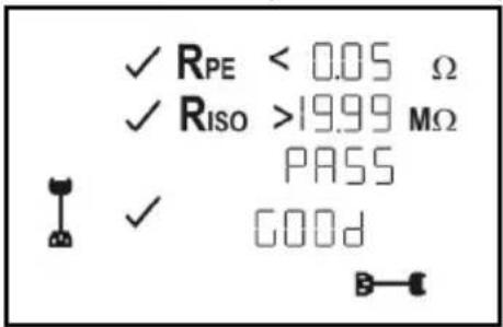
8.2.3.1 Testing of IEC power cords (IEC adapter cables)
- Connect the IEC power cord to be tested to the BENNING ST 710 by means of the IEC connector ±b and the test socket ±b .
- Press the key to start the automatic testing procedure.
- The test starts with measuring the protective conductor resistance R_PE
- Depending on whether the value is higher or lower than the limiting value, a indicated next to the R_PE symbol.

The protective conductor resistance depends on the length and cross-section of the line to be tested. It is possible that the measuring result is acceptable although the BENNING ST 710 indicates a next to the R PE symbol.
- Please refer to Table 1 for typical resistance values of lines.
Table 1: Resistance values of the protective conductor depending on length and cross-section
| Length | 1.0 mm² 1.5 mm² 2.5 mm² | ||
| 5 m 0.1 Ω 0.06 Ω 0.04 Ω | |||
| 10 m 0.2 Ω 0.12 Ω 0.08 Ω | |||
| 25 m 0.5 Ω 0.3 Ω 0.2 Ω | |||
| 50 m 1.0 Ω 0.6 Ω 0.4 Ω | |||
- After the R PE test has been passed, the measurement of the insulating resistance is carried out automatically.
Depending on whether the value is higher or lower than the limiting value, a or a x indicated next to the RISO symbol.
After the R_ISO test has been passed, the external conductor (L) and the neutral conductor (N) are checked for line breaks and short-circuits. A passed test regarding line breaks and short-circuits is indicated by a next to the end that "GOOD" symbol. - The "PASS" symbol confirms successful testing of the entire testing procedure.
-
If the test regarding line breaks and short-circuits has failed, one of the following symbols is indicated instead of the "GOOD" symbol:
-
"OPEN" symbol:
confirms a line break of the external conductor (L) or neutral conductor (N) - "Short" symbol:
confirms a short-circuit between the external conductor (L) and the neutral conductor (N) See figure 5a: Testing of device connecting cables with IEC connector
Note on measuring the protective conductor resistance:
- Alternatively, the measurement of the protective conductor resistance R_PE can be carried out as permanent measurement (max. 3 minutes). For this purpose press the key 2 for approx. >5 sec. until the symbol appears on the display. Check the connecting line of the test object by bending it over the entire length in order to detect weak points or a break of the protective conductor. The BENNING ST 710 continuously records the current measured value on the display and stores the maximum value in the memory. By pressing the key 4 again, the measurement is carried out with reversed polarity. Press the key 4 again to indicate the maximum value of R_PE on the display and to continue the testing procedure as described in section 8.2.3.1.
8.2.3.2 Testing of cable reels, multiple distributors and extension cables
- Connect the IEC power cord (IEC adapter cable) included in the scope of delivery to the IEC connector 7 of the BENNING ST 710.
- Connect the line to be tested to the test socket ① and to the shock-proof socket of the IEC power cord.
- Press the key 4 to start the automatic testing procedure.
The further testing procedure corresponds to the testing procedure described in section 8.2.3.1.
See figure 5b: Testing of lines, multiple distributors and cable reels
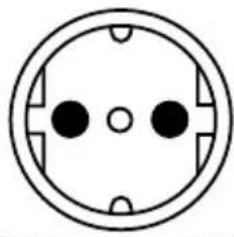
8.3 Voltage measurement on external shock-proof socket
- Connect the IEC power cord (IEC adapter cable) to the IEC connector 7 of the BENNING ST 710.
- Connect the shock-proof plug to the shock-proof socket to be tested. With the mains voltage being applied, the voltage measurement will start automatically.
Depending on the external conductor position (right or left) of the shock-proof socket, the voltage potentials between the connecting terminals L, N and PE are indicated.
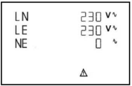
or
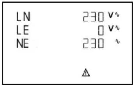

Only the voltage potentials between the individual connections L, N and PE are measured. The measurement does not provide any information on the proper installation of the shock-proof socket. There will be no warning in case of a dangerous contact voltage of the PE conductor!
See figure 6: Voltage measurement on external shock-proof socket
9. Maintenance

Before opening the BENNING ST 710, make sure that it is free of voltage! Electrical danger!
Work on the opened BENNING ST 710 under voltage must be carried out by skilled electricians with special precautions for the prevention of accidents only.
Make sure that the BENNING ST 710 is free of voltage as described below before opening the instrument:
- Switch the tester off.
- Remove all connecting cables from the object.
9.1 Securing the instrument
Under certain circumstances safe operation of the BENNING ST 710 is no longer ensured, for example in the case of:
Visible damage of the casing.
- Incorrect measurement results.
- Recognisable consequences of prolonged storage under improper conditions.
- Recognisable consequences of extraordinary transportation stress.
In such cases the BENNING ST 710 must be switched off immediately, disconnected from the measuring points and secured to prevent further utilisation.
9.2 Cleaning
Clean the exterior of the housing with a clean dry cloth (exception: special cleaning wipers). Avoid using solvents and/or scouring agents for cleaning the instrument. It is important to make sure that the battery compartment and battery contacts are not contaminated by leaking electrolyte.
If electrolyte contamination or white deposits occur in the area of the batteries or battery compartment, clean them too with a dry cloth.
9.3 Battery replacement

Before opening the BENNING ST 710, make sure that it is free of voltagel Electrical danger!
The BENNING ST 710 is supplied by means of six 1.5V batteries/ type AA (IEC LR6).
A battery replacement (see Figure 7) is required, if the battery symbol appears on the display unit 5.
Proceed as follows to replace the batteries:
- Switch the BENNING ST 710 off.
- Put the BENNING ST 710 face down and unscrew the screw of the battery compartment cover.
- Lift off the battery compartment cover (in the area of the housing slots) from the bottom part of the battery compartment.
- Remove the discharged batteries from the battery compartment.
- Then, insert the new batteries into the battery compartment at the provided places (please observe correct polarity of the batteries).
- Lock the battery compartment cover into place on the bottom part and tighten the screw.
See figure 7: Battery replacement

Make your contribution to environmental protection! Do not dispose of discharged batteries in the household garbage. Instead, take them to a collecting point for discharged batteries and special waste material. Please inform yourself in your community.
9.4 Calibration
Benning guarantees compliance with the technical and accuracy specifications stated in the operating manual for the first 12 months after the delivery date. To maintain the specified precision of the measurement results, the instrument must be recalibrated at regular intervals by our factory service. We recommend a recalibration interval of one year. Send the appliance to the following address:
10. Environmental note

At the end of the product's useful life, please dispose of the device at collection points provided in your community.