CC 3 - Measuring equipment BENNING - Free user manual and instructions
Find the device manual for free CC 3 BENNING in PDF.

| Product type | Electric clamp adapter for current measurement |
| Brand | BENNING |
| Model | CC 3 |
| Dimensions (L × W × H) | 185 × 66 × 40 mm |
| Weight | 270 g |
| Power supply | 9 V battery (IEC 6LR61) |
| Battery life | Approximately 66 hours (alkaline) |
| Measuring ranges | 40 A and 300 A DC and AC |
| Voltage output | 10 mV/A (40 A range), 1 mV/A (300 A range) |
| Accuracy (40 A DC/AC) | ± (2.0% + 0.2 A) |
| Accuracy (300 A, 40-200 A) | ± (2.0% + 1 A) |
| Accuracy (300 A, 200-300 A) | ± (2.9% + 2 A) |
| Maximum jaw opening | 25 mm |
| Maximum conductor diameter | 22 mm |
| Overvoltage category | 600 V CAT III |
| Protection rating | IP30 |
| Operating temperature | 0 °C to 50 °C (depending on humidity) |
| Storage temperature | -20 °C to +60 °C |
| Main functions | DC and AC current measurement up to 300 A, zero compensation, automatic power-off (APO) |
| Maintenance and cleaning | Clean with a dry cloth, no solvents. Replace the battery when the red LED lights up. |
| Safety | Double insulation (class II), maximum voltage to ground: 600 V |
| Included accessories | Current clamp with safety spiral cable, angled 4 mm connectors, protective case, 9 V battery, instruction manual |
Frequently Asked Questions - CC 3 BENNING
User questions about CC 3 BENNING
0 question about this device. Answer the ones you know or ask your own.
Ask a new question about this device
Download the instructions for your Measuring equipment in PDF format for free! Find your manual CC 3 - BENNING and take your electronic device back in hand. On this page are published all the documents necessary for the use of your device. CC 3 by BENNING.
USER MANUAL CC 3 BENNING
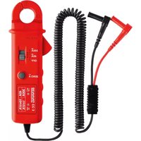
Fig.1: Appliance front face
Operating instructions BENNING CC 3
Current clamp adapter for direct and alternating current measurement
Contents
- User notes
- Safety note
- Scope of delivery
- Description of appliance tester
- General information
- Environment conditions:
- Electrical specifications
- Making measurements with the BENNING CC 3
- Maintenance
- Environmental notice
1. User notes
These operating instructions are intended for
- skilled electricians and
-trained electrical personnel.
The BENNING CC 3 is intended for making measurements in dry environment. It must not be used for making measurements in electric circuits with a nominal voltage greater than 600V DC/AC (for further details, see Section 6. "Environmental conditions").
The following symbols are used in these operating instructions and on the BENNING CC 3:

Application around and removal from HAZARDOUS LIVE conductors is permitted.

Warning of electrical danger!
Indicates instructions which must be followed to avoid danger to persons.

Important, comply with the documentation!
The symbol indicates that the information provided in the operating instructions must be complied with in order to avoid risks.

This symbol on the BENNING CC 3 means that the BENNING CC 3 is totally insulated (protection class II).

This symbol on the BENNING CC 3 means that the BENNING CC 3 complies with the EU directives.

(AC) Alternating voltage or current.

(DC) Direct voltage or current.

Earth (voltage against earth).
2. Safety note
The instrument is built and tested in accordance with
DIN VDE 0411 part 1/ EN 61010-1
DIN VDE 0411 part 2-032/ EN 61010-2-032
DIN VDE 0411 part 031/ EN 61010-031
and has left the factory in perfectly safe technical state.
To maintain this state and ensure safe operation of the appliance tester, the user must observe the notes and warnings given in these instructions at all times.
Improper handling and non-observance of the warnings might involve severe injuries or danger to life.

WARNING! Be extremely careful when working with bare conductors or main line carrier! Contact with live conductors will cause an electric shock!

The unit may be used only in power circuits within the over voltage category III with a conductor for 600V max. to earth. Remember that work on electrical components of all kinds is dangerous. Even low voltages of 30V AC and 60V DC may be dangerous to human life.

Before starting the appliance tester up, always check it as well as all leads and wires for signs of damage.
Should it appear that safe operation of the appliance tester is no longer possible, it should be shut down immediately and secured to prevent it being switched on accidentally.
It may be assumed that safe operation is no longer possible:
- if the instrument or the measuring leads show visible signs of damage, or
- if the appliance tester no longer functions, or
- after long periods of storage under unfavourable conditions, or
- after being subjected to rough transport.

In order to avoid danger,
- do not touch the bare prod tips of the measuring leads connectors,
- insert the measurement leads in the appropriately designated measuring sockets on the multimeter
3. Scope of delivery
The scope of delivery for the BENNING CC 3 comprises:
3.1 One item BENNING CC 3 with a securely connected spiral type safety measuring lead featuring a 90^ -angled 4mm safety connector,
3.2 One compact protective pouch,
3.3 One 9-V block battery (integrated in the new unit when it is supplied),
3.4 One operating instructions manual
4. Description of appliance tester
The current clamp adapter BENNING CC 3 is a measuring adapter for analog and digital multimeters and is used for direct and alternating current measurements up to 300 A.
See figure 1: Appliance front face
The display and operator control elements specified in Fig. 1 are designated as follows:
Measuring clamp, for clamping on the single wire alternating current conductor.
Current probe bulge, protects against contact with conductor.
Opening lever, for opening and closing the measuring pliers.
Sliding switch, intended to select the measuring ranges
OFF switch
-
DC and AC current measurement up to 40 A,
-
DC and AC current measurement up to 300 A,
„ZERO“ key (null balance key), allows null balance for direct current (DC) measurements,
Red LED (low battery indication), lights in case of discharged battery or announced the automatic switch off after approx. 30 minutes (APO, AutoPower-Off).
Green LED ("ON" LED), flashes when the device is switched on,
Housing with label area
Spiral type safety measuring lead with 4 mm safety connector, red, black,
90^ -angled.
5. General information
5.1 General details on the current clamp adapter
5.1.1 The sliding switch 4 is intended to select the measuring ranges of 40 A or 300 A AC/ DC.
5.1.2 The „ZERO“ key (null balance key) ⑤ is intended to carry out a null balance for direct current (DC) measurements. With the measuring clamp ① being closed, press and hold the „ZERO“ key ⑤ until a measured value of approximately 0V is displayed on the multimeter.
5.1.3 The BENNING CC 3 switches off automatically after approx. 30 minutes (APO, Auto-Power-Off). It can be powered on again by pushing switch 4. The automatic switch off is signaled by means of the illumination of the red LED (low battery indicator) 6.
5.1.4 The BENNING CC 3 is powered by one 9-V block battery (IEC 6 LR 61).
5.1.5 If the battery voltage falls below the specified operating voltage of the BENNING CC 3, the red LED (battery indication) starts lighting.
5.1.6 The life span of a battery is approx. 66 hours (alkali battery).
5.1.7 Sensor type: Hall sensor for direct and alternating current.
5.1.8 Temperature coefficient of the measured value: 0.2 × (stated measuring precision)/ ^ C < 18^ C or >28^ C , related to the value for the reference temperature of 23^ C .
5.1.9 Largest opening of pliers: 25mm
5.1.10 Maximum conductor diameter: 22mm
5.1.11 Appliance dimensions: (L × W × H) = 185 × 66 × 40 ~mm
5.1.12 Appliance weight: 270 g
6. Environment conditions
- The BENNING CC 3 is intended for making measurements in dry environment.
- Maximum barometric elevation for making measurements: 2000m
-Overvoltage category IEC 60664/IEC 61010,600 V category III, - Contamination degree 2 according to EN 61010-1
Protection Class: IP 30 (DIN VDE 0470-1 IEC/ EN 60529)
IP 30 means: Protection against access to dangerous parts and protection against solid impurities of a diameter >2.5mm , (3 - first index). No protection against water, (0 - second index).
- Operating temperature and relative humidity:
For operating temperatures from 0^ to 30^ : relative humidity less than 80%
For operating temperatures from 31^ to 40^ : relative humidity less than 75%
For operating temperature from 41^ to 50^ : relative humidity less than 45%
- Storage temperature: The BENNING CC 3 can be stored at any temperature in the range from -20 °C to +60 °C.
7. Electrical specifications
Note: The measuring precision is specified as the sum of
-
a relative fraction of the measured value and
-
a current value in A.
The measurement precision applies at a temperature of 23^ ± 5^ and a relative humidity less than 75% .
7.1 Direct current ranges
Output voltage: 10mVDC / ADC in the 40 A measuring range 1mVDC / ADC in the 300 A measuring range
| Measurement range | Measured value | Output | Measurement precision* |
| 40 A | 0 . . . 40 A | 0 . . . 400 mV | ± (2.0 % + 0.2 A) |
| 300 A | 40 . . . 200 A | 40 . . . 200 mV | ± (2.0 % + 1 A) |
| 200 . . . 300 A | 200 . . . 300 mV | ± (2.9 % + 2 A) |
The measuring accuracy is specified for a sinusoidal curve. The stated precision is specified for conductors that are centrally clamped by the measuring clamp (see Fig. 2). For conductors that are not centrally clamped, an additional error of 1% of the display value needs to be taken into account. Load impedance: min. 10M (input resistance of the multimeter)
7.2 Alternating current ranges
Output voltage: 10mVAC / AAC in the 40 A measuring range 1mVAC / AAC in the 300 A measuring range
| Measurement range | Measured value Output | Measurement precision* within the frequency range 40 Hz - 400 Hz |
| 40 A 0 . . . 40 A 0 . . . 400 mV ± (2.0 % + 0.2 A) | ||
| 300 A | 40 . . . 200 A 40 . . . 200 mV ± (2.0 % + 1 A) | |
| 200 . . . 300 A 200 . . . 300 mV ± (2.9 % + 2 A) | ||
The measuring accuracy is specified for a sinusoidal curve. The stated precision is specified for conductors that are centrally clamped by the measuring pliers (see Fig. 2). For conductors that are not centrally clamped, an additional error of 1% of the display value needs to be taken into account. Load impedance: min. 10M (input resistance of the multimeter)
8. Making measurements with the BENNING CC 3
8.1 Preparations for making measurements
Operate and store the BENNING CC 3 only at the specified storage and operating temperatures. Avoid continuous insulation.
- The nominal voltage and current ratings of the safety measuring leads included in the scope of delivery correspond to the ratings of the BENNING CC 3.
The safety measuring lead is securely connected to the BENNING CC 3 and cannot be removed. - Check the insulation of the safety measuring leads. Discard the BENNING CC 3 immediately if the insulation is damaged.
- Do not clamp the measuring pliers on a live conductor before the BENNING CC 3 has not been connected to a multimeter.
- Strong sources of interference in the vicinity of the BENNING CC 3 can lead to unstable readings and measuring errors.
- Do not apply any voltage to the output contacts of the BENNING CC 3.

Do not exceed the maximum permitted voltage with respect to earth potential! Electrical danger!
The highest voltage, that may be applied to the BENNING CC 3 against ground potential, is 600V .
8.2 Direct current measurement
- Select the measuring range (40 A or 300 A) by means of the sliding switch 4.
- Set the multimeter to the function "direct voltage measurement" (V DC) and select a measurement range that can display voltages from 1 mV to 400 mV.
- Contact the 4 mm safety connector of the spiral type safety measuring lead with the COM jack of the multimeter.
- Contact the red 4 mm safety connector of the spiral type safety measuring lead with the voltage input jack (V) of the multimeter.
- Press and hold the "ZERO" key (null balance key) ⑤ until a measured value of approximately 0V is displayed on the multimeter. For this purpose, close the measuring clamp ① and remove it from the live conductor (external field).
- Opening lever ③ operate and use measuring clamp ① to clamp the single wire live conductor.
- Read off the voltage value on the multimeter and convert to the current value taking into account the conversion factor.
40 A measuring range: 10 mV/A
300 A measuring range: 1mV / A
(see housing with label field 8)
Example:
Measuring range: 300 A
Voltage value indicated on multimeter: 0.250VDC = 250mV DC, corresponds to a measured current value of 250 A DC.
See figure 2: AC/ DC current measurement
8.3 Alternating current measurement
- Select the measuring range (40 A or 300 A) by means of the sliding switch ④.
- Set the multimeter to the function "alternating voltage measurement" (VAC) and select a measurement range that can display voltages from 1mV to 400mV .
- Contact the 4mm safety connector of the spiral type safety measuring lead with the COM jack of the multimeter.
-
Contact the red 4 mm safety connector of the spiral type safety measuring lead with the voltage input jack (V) of the multimeter.
-
Opening lever ③ operate and use measuring clamp ① to clamp the single wire live conductor.
- Read off the voltage value on the multimeter and convert to the current value taking into account the conversion factor.
40 A measuring range: 10mV / A
300 A measuring range: 1mV/A
(see housing with label field 8
Example:
Measuring range: 300 A
Voltage value indicated on multimeter: 0.250V AC = 250mV AC, corresponds to a measured current value of 250 A AC.
See figure 2: AC/ DC current measurement
9. Maintenance

Before opening the BENNING CC 3, make sure that it is disconnected from all voltages! Electrical danger!
Work on the opened BENNING CC 3 under voltage may be carried out only by skilled electricians with special precautions for the prevention of accidents.
Make the BENNING CC 3 voltage free as follows before opening the instrument:
- First remove the BENNING CC 3 from the measuring object.
- Then disconnect the two safety measuring leads from the multimeter.
The BENNING CC 3 current clamp adapter is not equipped with a fuse.
9.1 Securing the instrument
Under certain circumstances safe operation of the BENNING CC 3 is no longer ensured, for example in the case of:
Visible damage of the casing.
- Incorrect measurement results.
- Recognisable consequences of prolonged storage under improper conditions.
- Recognisable consequences of extraordinary transportation stress.
In such cases the BENNING CC 3 must be disconnected from the measuring point immediately and secured to prevent further utilisation.
9.2 Cleaning
Clean the outside of the unit with a clean dry cloth. (Exception: any type of special cleaning cloth). Never use solvents or abrasives to clean the testing unit. Ensure that the battery compartment and the battery contacts have not been contaminated by electrolyte leakage.
If any electrolyte or white deposits are seen near to the battery or in the battery compartment, remove them with a dry cloth, too.
9.3 Battery replacement

Before opening the BENNING CC 3, ensure that it is not connected to a source of voltage! Electrical hazard!
The BENNING CC 3 is powered by 9-V block battery. Battery replacement (see figure 3) is required, if the red LED (battery indication) lights.
To replace the battery, proceed as follows:
- Remove the BENNING CC 3 from the object to be measured.
- Disconnect the safety measuring leads from the multimeter.
- Switch the sliding switch 4 to position "OFF".
- Lay the BENNING CC 3 on its front and loosen the screw from the cover of the battery compartment.
- Lift the battery compartment cover (at the recesses in the housing) off the bottom part.
- Lift the discharged battery out of the battery compartment and remove the battery leads carefully from the battery.
- Connect the new battery with the battery leads and arrange them in such a way that they are not crushed between the two halves of the housing. Then place the battery in the correct position in the battery compartment.
- Clip the battery cover onto the bottom part and tighten the screw.
See fig. 3: Battery replacement

Remember the environment! Do not dispose of used batteries with domestic waste. Dispose of them at a battery-collection point or as toxic waste. Your local authority will give you the information you need.
9.4 Calibration
Benning guarantees compliance with the technical and accuracy specifications stated in the operating manual for the first 12 months after the delivery date. To maintain the specified accuracy of the measurement results, the instrument must be recalibrated at regular intervals by our factory service. We recommend a recalibration interval of one year. Send the appliance to the following address:
At the end of the product's useful life, please dispose of it at appropriate collection points provided in your country.
automatische uitschakeling na ca. 30 minutes (APO, Auto Power Off).