
AKFH 185 Select - Milling machine Fein - Free user manual and instructions
Find the device manual for free AKFH 185 Select Fein in PDF.

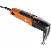
| Product type | Portable chamfering router |
| Brand | Fein |
| Model | AKFH 185 Select |
| Use | Professional, chamfering and edge machining for weld preparation |
| Power supply | FEIN battery (accumulator) |
| Accumulator type | Compatible with FEIN chargers, charging temperature 5°C to 45°C |
| Charge status indicator | Green LEDs (charge level) and red LED (battery almost empty or not ready) |
| Battery protection | Automatic shut-off in case of deep discharge |
| Chamfer height adjustment | Graduation with tolerance ±1 mm, fine adjustment in steps of 0.1 mm |
| Speed adjustment | 6 speed levels depending on the material |
| Machinable materials | Steel, stainless steel, aluminum, aluminum alloys, brass, plastic |
| Accessories | Removable chamfering inserts, radius inserts, guide roller |
| Required protective equipment | Safety glasses, hearing protection, gloves, dust mask if necessary |
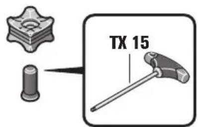
| Maintenance | Blow the ventilation slots with dry compressed air, clean and lubricate the thread of the adjustment device |
| Compliance | EU directives, double insulation |
Frequently Asked Questions - AKFH 185 Select Fein
User questions about AKFH 185 Select Fein
0 question about this device. Answer the ones you know or ask your own.
Ask a new question about this device
Download the instructions for your Milling machine in PDF format for free! Find your manual AKFH 185 Select - Fein and take your electronic device back in hand. On this page are published all the documents necessary for the use of your device. AKFH 185 Select by Fein.
USER MANUAL AKFH 185 Select Fein
natural_image
Illustration of two robotic arms with mechanical components, no text or symbols present| AKFH18-5 (**) AKFH18-5T (**)7 138 01 .. 7 138 02 .. | |||
| UV | 1 | --- | 8 |
| n_0 | /min, min ^-1 , rpm, r/min 7500 7500 | ||
| α° max. 80 max. 80c (max., 45°) mma (max., 45°) mm 3,5 3,5 | 5,0 5,0 | ||
| R mm 1,2 / 2,5 | 1,2 / 2,5 | ||
| SX SX | |||
| kg 2,4 2,4 | |||
| L_pA | dB | 85 85 | |
| K_pA | dB 3 | 3 | |
| L_wA | dB | 96 96 | |
| K_wA | dB 3 | 3 | |
| L_pCpeak | dB | 100 100 | |
| K_pCpeak | dB 3 | 3 | |
| B18A | ||
| High Power Lithium Ion | ||
| U | V== | 18 |
| kg | 0,75 | |
| ALG 30, ALG 50, ALG 80 (**) | ||
| 3 | 4 | |||||||||
| de | 20 | pt | 58 | tr | 95 | sl | 134 | et | 173 | th |
| en | 26 | el | 64 | hu | 101 | sr | 140 | lt | 179 | ja |
| fr | 32 | da | 71 | cs | 108 | hr | 146 | lv | 185 | hi |
| it | 39 | no | 77 | sk | 114 | ru | 152 | zh(CM) | 191 | ar |
| nl | 46 | sv | 83 | pl | 121 | uk | 159 | zh(CK) | 197 | |
| es | 52 | fi | 89 | ro | 128 | bg | 166 | ko | 202 |

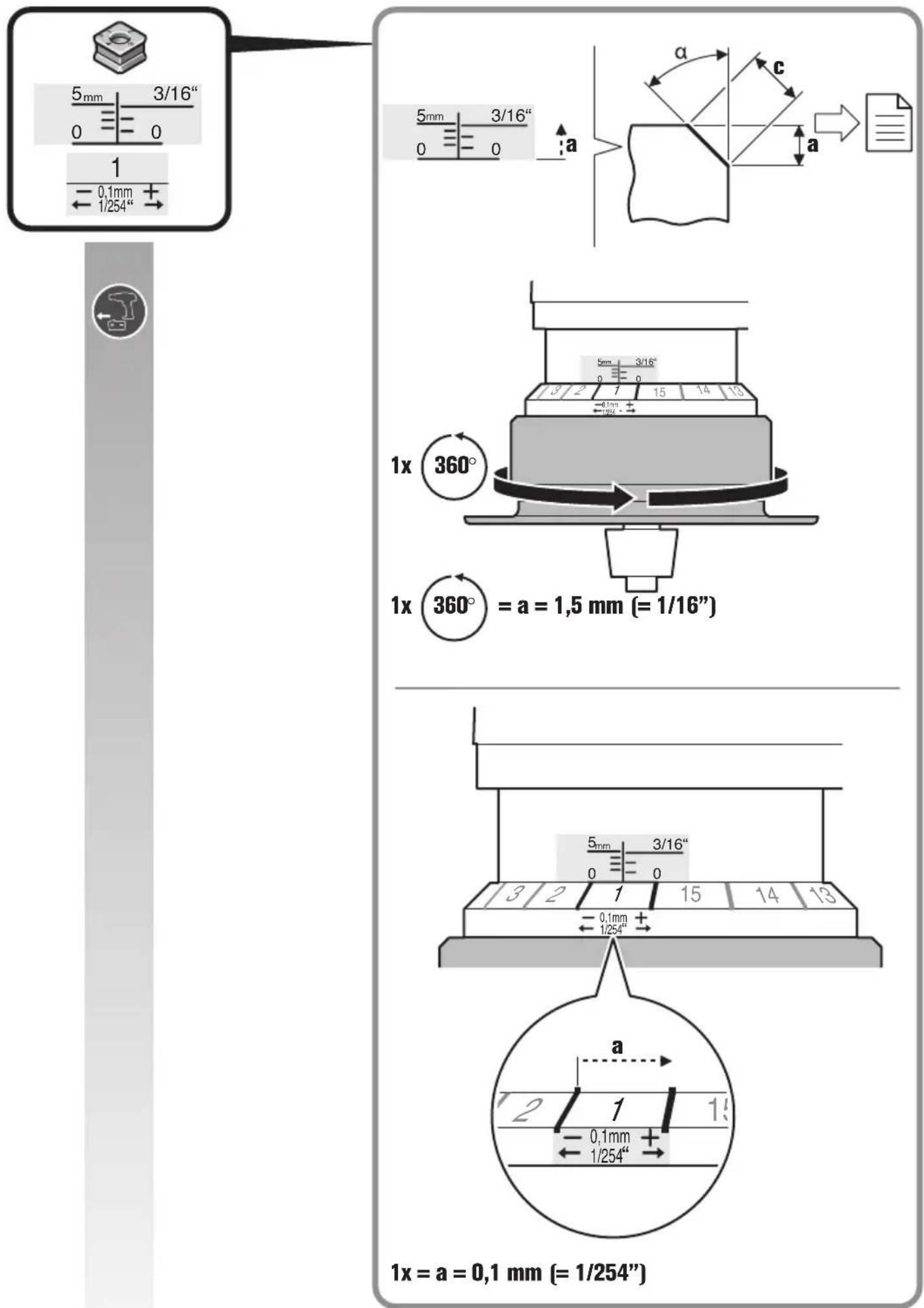
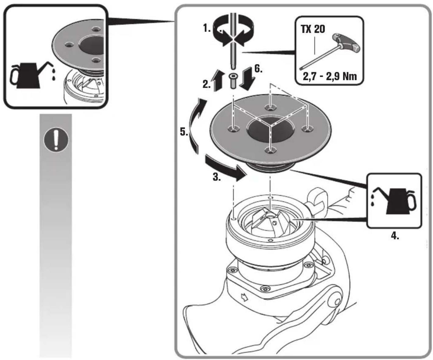
1x = a = 0,1 mm (= 1/254")
flowchart
graph TD
    A["Start: 5mm 3/16" with 0, 0, 1, 0.1mm, 1/254" displacement"] --> B["Step 1: X → [Image of mechanical part"]
    B --> C["Step 2: ✓ → [Image of presser or fixture"]
    C --> D["Step 3: ✓ → [Image of presser or fixture"]
    D --> E["End: Step 4: ✓ → [Image of presser or fixture"]
natural_image
Simple line drawing of a 3D block with an arrow indicating direction, enclosed in a rounded square (no text or symbols)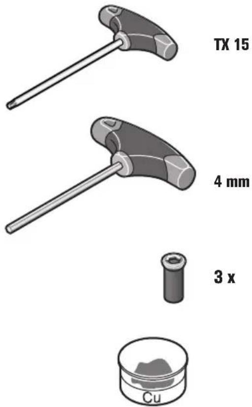
natural_image
Mechanical assembly diagram of a robotic arm with directional arrows indicating motion (no text or symbols)A
SX B.
B
SX / R2,5
C
Translation of the Original Instructions.
Symbols, abbreviations and terms used.
| Symbol, character Explanation | |
 | Make sure to read the enclosed documents such as the Instruction Manual and the General Safety Instructions. |
 | Observe the instructions in the text or graphic opposite! |
 | Observe the instructions in the text or graphic opposite! |
 | General prohibition sign. This action is prohibited. |
 | Before commencing this working step, remove the battery from the power tool. Otherwise there may be danger of injury caused by unintentional starting of the power tool. |
 | Do not touch the rotating parts of the power tool. |
 | Use eye protection during operation. |
 | Use ear protection during operation. |
 | Use protective gloves during operation. |
 | Warning against sharp edges of application tools, such as the cutting edges of the cutter blades. |
| [GH48] | A surface that can be touched may be very hot and thus hazardous. |
 | Gripping surface |
 | Additional information. |
| [XX7K] | Confirms the conformity of the power tool with the directives of the European Community. |
| [D27X] | This sign indicates a possible dangerous situation that could cause severe or fatal injury. |
 | Worn out power tools and other electrotechnical and electrical products should be sorted separately for environmental-friendly recycling. |
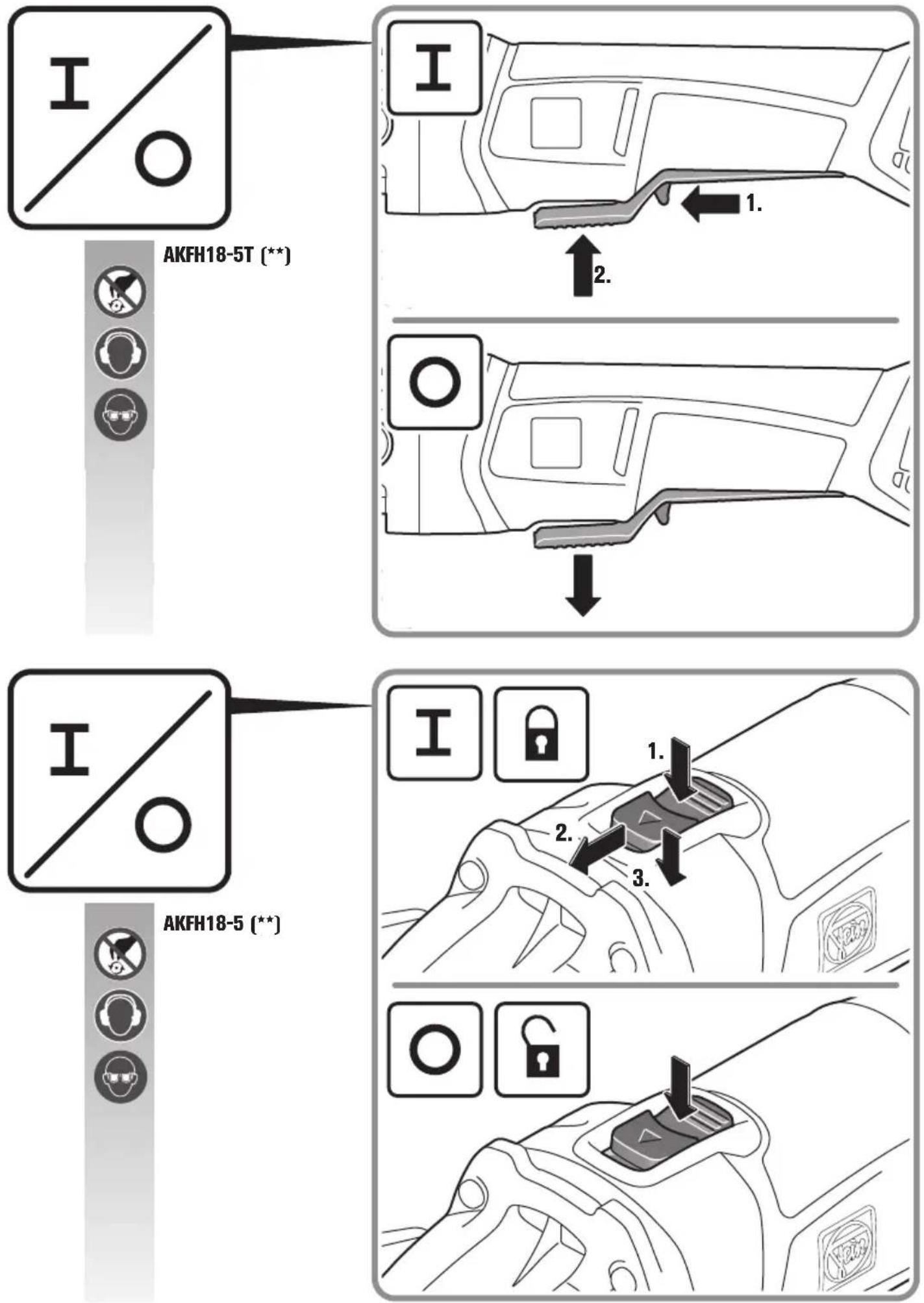
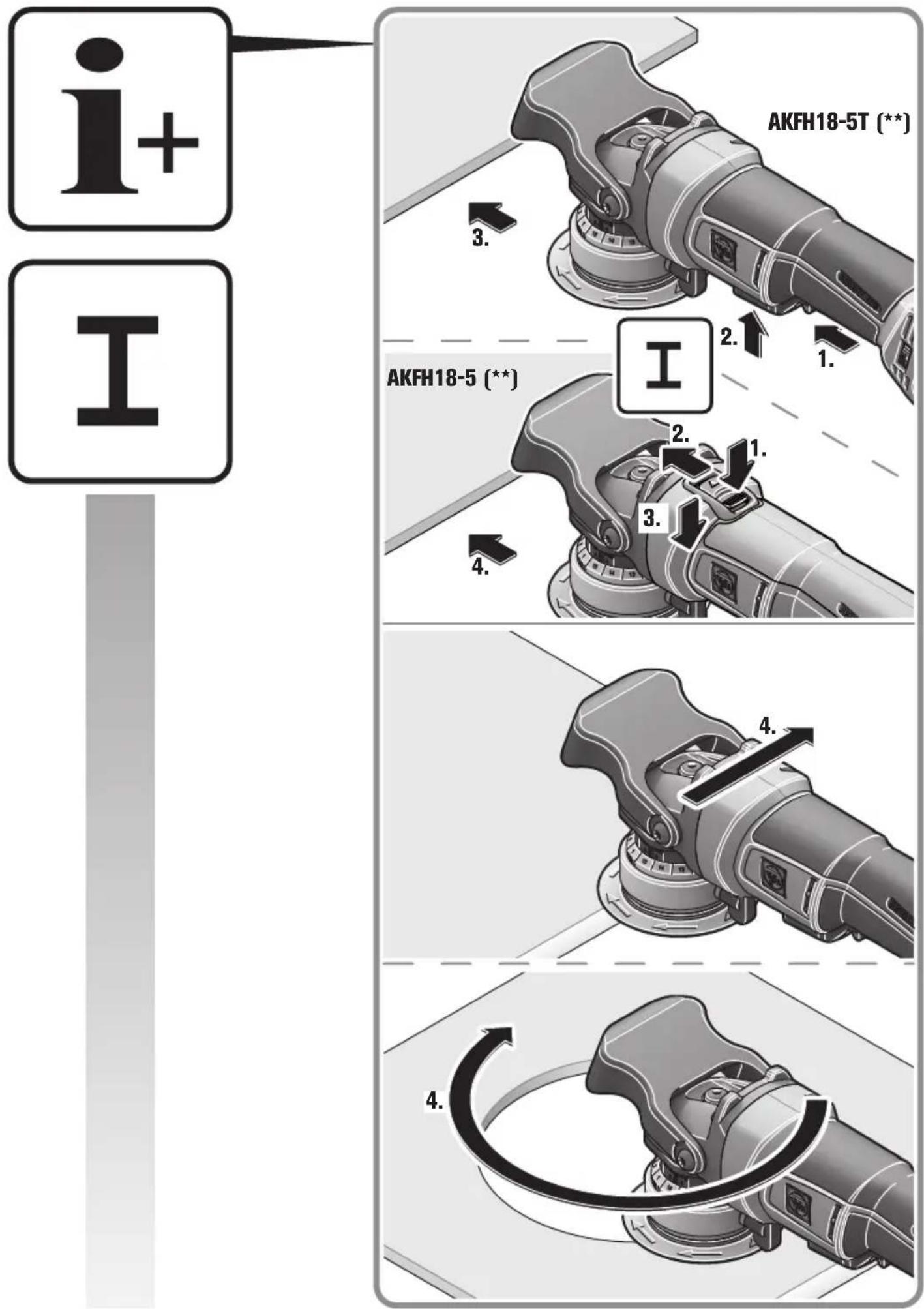
 | Switching on |
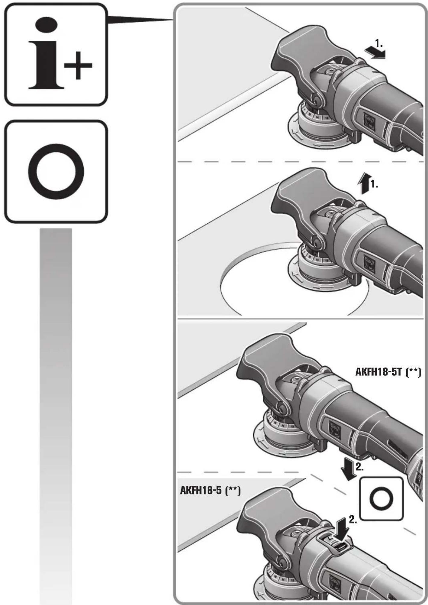
 | Switching off |
 | Locked |
 | Not locked |
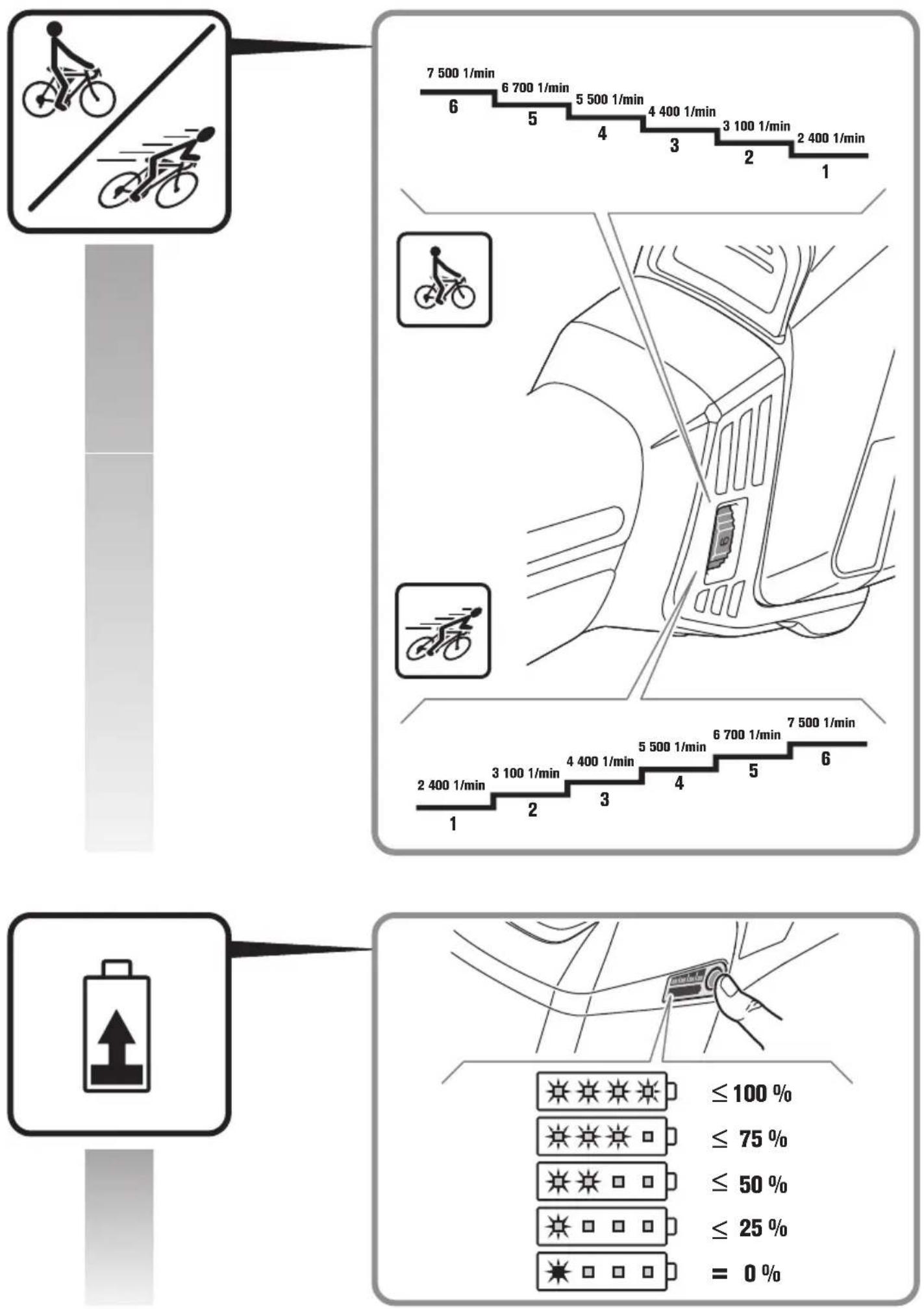
 | Low speed |
 | High speed |
 | Battery type |
 | Charger type |
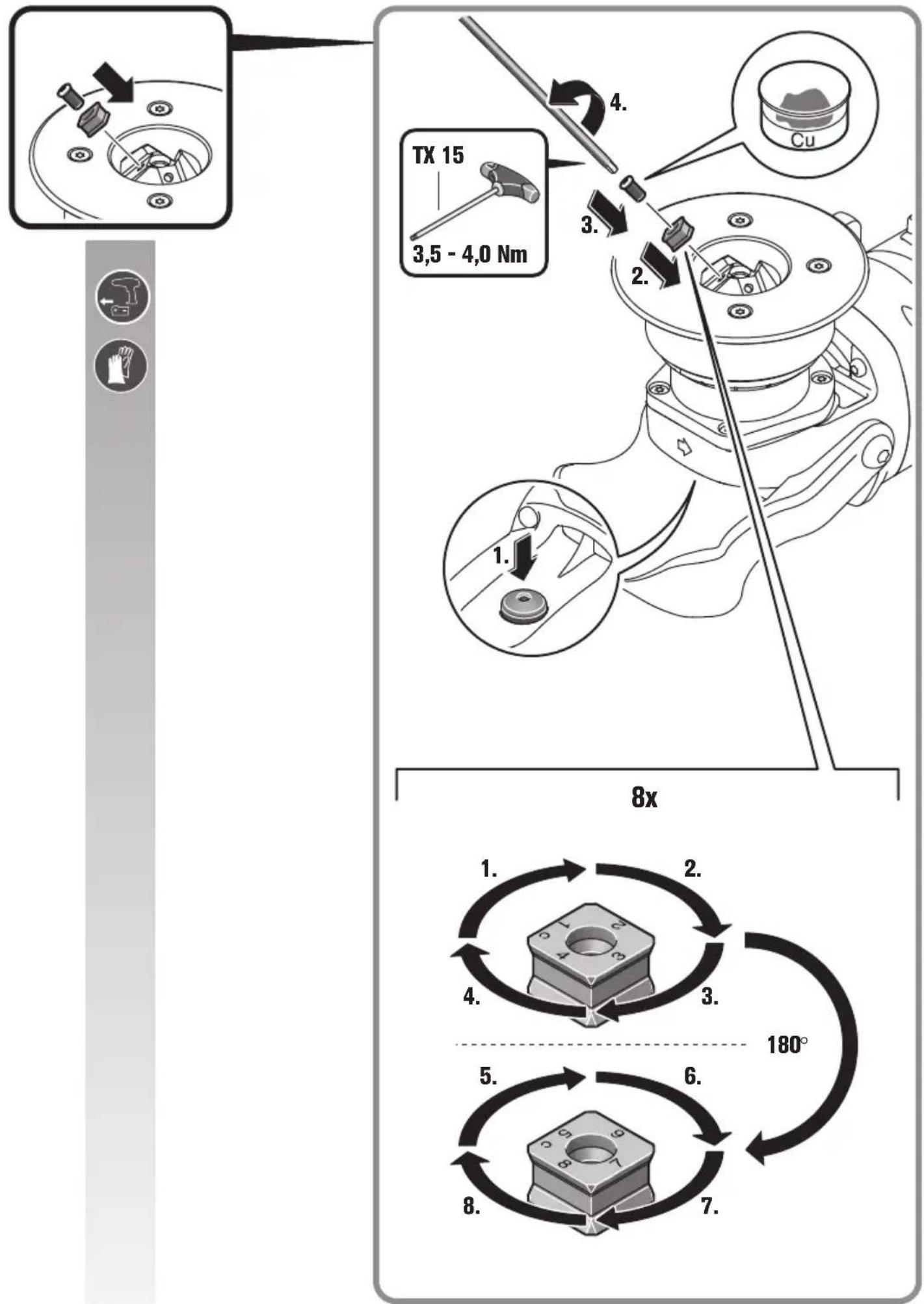
 | Type: indexable insert |
 | Copper paste (Cu) |
 | See section “Operating Instructions” |
 | Apply oil |
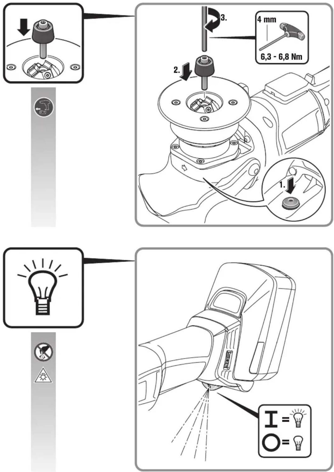
 | Caution: Do not view into the switched-on lamp! |
| (**) may contain numbers and letters | |
| (Ax – Zx) Marking for internal purposes | |
| Character Unit of measurement, international | Unit of measurement, national | Explanation | |
| UV | = V | = D | C v |
| n_0 | /min, min ^-1 , rpm, r/min | rpm Rated no-load speed (with fully charged battery) | |
| fHz Hz Frequency | |||
| M... | mm mm Size of metric | thread | |
| ∅ mm mm Diameter of a round part | |||
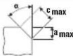 | ° | ° | α=bevel angle (milling head angle) |
| mm mm c (max., 45°)=max. bevel length | a (max., 45°)=max. bevel height (setting dimension) | ||
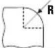 | mm mm R=radius | ||
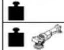 | kg | kg | Weight according to EPTA-Procedure 01 |
| kg | kg | Weight of the power tool without battery and application tool | |
 | kg | kg | Weight of the battery |
 | dB | dB | Sound pressure level |
| dB | dB | Sound power level | |
 | dB | dB | Peak sound pressure level |
| Uncertainty | |||
 | m/s ^2 | m/s ^2 | Vibrational emission value according to EN 62841 (vector sum of three directions) |
| m, s, kg, A, mm, V, W, Hz, N, °C, dB, min, m/s ^2 | m, s, kg, A, mm, V, W, Hz, N, °C, dB, min, m/s ^2 | Basic and derived units of measurement from the international system of units SI. | |
For your safety.
WARNING
Read all safety warnings and all instructions. Failure to follow the
warnings and instructions may result in electric shock, fire and/or serious injury.
Save all warnings and instructions for future reference.

Do not use this power tool before you have thoroughly read and completely understood this Instruction Manual and the enclosed "General
Safety Instructions" (document number
3 41 30 465 06 0). The documents mentioned should be kept for later use and enclosed with the power tool, should it be passed on or sold.
Please also observe the relevant national industrial safety regulations.
Intended use of the power tool:
hand-guided bevel milling machine for professional use by instructed operating personnel in weather-protected environments using the application tools and accessories recommended by FEIN:
- for machining workpieces made of steel, cast steel, fine-grained steel, stainless steel, aluminium, aluminium alloys, brass and plastic
- for commercial use in industry and trade
- for the preparation of K-, V-, X- and Y-shaped welding joints
- for machining visible edges in plant, equipment and general engineering
- for rounding edges for optimal paint preparation or as impact protection
Special safety instructions.
Fasten and secure the workpiece with screw clamps or other suitable clamps to a stable surface. When holding the workpiece manually it is unstable and can lead to loss of control and injury.
Do not use accessories which are not specifically designed and recommended by the tool manufacturer. Just because the accessory can be attached to your power tool, it does not assure safe operation.
Do not use a damaged accessory. Before each use, check the indexable inserts for chipping and cracks, wear or heavy use. If the machine or application tool is dropped, inspect for damage or install an undamaged application tool.
Wear personal protective equipment. Depending on application, use face shield, safety goggles or safety glasses. Where appropriate, wear dust mask, hearing protectors, gloves and workshop apron capable of stopping small abrasive or workpiece fragments. The eye protection must be capable of stopping flying debris generated by various operations. The dust mask or respirator must be capable of filtrating particles generated by your operation. Prolonged exposure to high intensity noise may cause hearing loss.
Keep bystanders a safe distance away from work area. Anyone entering the work area must wear personal protective equipment. Fragments of workpiece or of a broken accessory may fly away and cause injury beyond immediate area of operation.
Always hold the power tool firmly when starting it. The reaction torque of the motor, as it accelerates to full speed, can cause the power tool to twist.
If possible, use clamps to fasten or affix the workpiece. Never hold a workpiece in one hand and the power tool in the other hand while in use. Clamping workpieces allows you to use both hands for better control the power tool.
Never lay the power tool down until the accessory has come to a complete stop. The spinning accessory may grab the surface and pull the power tool out of your control.
Do not run the power tool while carrying it at your side. Accidental contact with the spinning accessory could snag your clothing, pulling the accessory into your body.
Regularly clean the power tool's air vents. The motor's fan will draw the dust inside the housing and excessive accumulation of powdered metal may cause electrical hazards.
Do not operate the power tool near flammable materials. Sparks could ignite these materials.
Do not use accessories that require liquid coolants.
Using water or other liquid coolants may result in electrocution or shock.
Secure the work piece firmly. A work piece that is gripped tightly in a clamping device or vice, is more secure than if held by hand.
Kickback and related warnings
Kickback is the sudden reaction to a pinched or snagged rotating application tool. Pinching or snagging causes the rotating application tool to rapidly stop. This can cause a power tool to be forced in the opposite direction to the rotating application tool at the point of binding.
For example, if the indexable insert is snagged or pinched in the workpiece, the edge of the indexable insert entering into the workpiece can get caught, causing the indexable insert to break out or cause kickback. The indexable-insert holder may either jump toward or away from the operator, depending on the direction of the indexable-insert holder at the point of binding. Indexable inserts can also break under these conditions. Kickback is the result of power tool misuse or incorrect operating procedures. It can be avoided by taking proper precautions as described below.
Maintain a firm grip on the power tool and position your body and arms to allow you to resist kickback forces. The operator can control torque reactions or kickback forces, if proper precautions are taken.
Use special care when working corners, sharp edges, etc. Avoid bouncing and snagging the accessory. Corners, sharp edges or bouncing have a tendency to snag the rotating accessory and cause loss of control or kickback.
Always feed the application tool into the material in the same direction as the cutting edge is exiting from the material (which is the same direction as the chips are thrown). Guiding the power tool in the wrong direction causes the cutting edge of the application tool to climb out of the workpiece and pull the tool in the direction of this feed.
Do not jam or seize the indexable insert or apply excessive pressure. Do not set a larger bevel height than the maximum allowed. Overstressing the indexable inserts increases the loading and susceptibility to wedging or snagging in the cut, and thus increases the possibility of kickback or indexable insert breakage.
Do not position your body directly in front or behind the indexable insert when operating the machine, position yourself parallel to the cutting surface. When moving the indexable inserts into the workpiece any potential kickback could result in contact with the indexable inserts.
Turn or replace blunt indexable inserts or those with worn off coating in good time. Blunt indexable inserts increase the risk of the machine jamming and breaking out.
Do not use the power tool without the guide plate.
Further safety warnings


Use ear protection during operation.
Indexable inserts, indexable-insert holder, workpiece and chippings can be hot after working. Wear protective gloves.
Use only sharp, undamaged indexable inserts.
Keep your hands away from the milling area and the application tools.
Do not direct the power tool against yourself, other persons or animals. Danger of injury from sharp or hot application tools.
Use a stationary extraction system and frequently blow out the ventilation slots. When working metal under extreme operating conditions, it is possible for conductive dust to settle in the interior of the power tool. The total insulation of the power tool can be impaired.
Do not rivet or screw any name-plates or signs onto the power tool. If the insulation is damaged, protection against an electric shock will be ineffective. Adhesive labels are recommended.
Do not work materials containing magnesium. Danger of fire.
Do not work CFP (carbon-fiber-reinforced polymer) and materials containing asbestos. These materials are considered carcinogenic.
Replace a damaged or cracked auxiliary handle. Do not operate the power tool with a defective auxiliary handle.
Use and handling of the battery (battery pack).
To avoid hazardous situations such as burns, fire, explosion, skin injuries, and other injuries when handling the battery, observe the following instructions:
Batteries must not be disassembled, opened or reduced in size. Do not subject batteries to mechanical impact or shock. Hazardous vapours and fluid can escape in case of damage and improper use of the battery. The vapours can irritate the respiratory system. Liquid ejected from the battery may cause skin irritations or burns.
When battery fluid from a damaged battery has come into contact with objects close by, check the respective components, clean them or replace them as required.
Keep the battery away from heat and fire. Do not store the battery in direct sunlight.
Do not remove the battery from its original packaging until it is going to be used.
Before any work on the machine itself, remove the battery from the power tool. If the power tool accidentally starts, there is danger of injury.
Remove the battery only when the power tool is switched off.
Keep the battery away from children.
Keep the battery clean and protect it against moisture and water. Clean contaminated battery terminals and power tool connections with a dry, clean cloth.
Charge the batteries only with battery chargers recommended by the manufacturer. A charger that is suitable one type of battery pack may create a risk of fire when used with another battery pack.
Keep the battery not being used away from paper clips, coins, keys, nails, screws or other small metal objects, that can make a connection from one terminal to another. Shorting the battery terminals together may cause burns or a fire.
Remove the power tool's battery during transport and storage.
Use only intact original FEIN batteries that are intended for your power tool. When working with and charging incorrect, damaged, repaired or reconditioned batteries, imitations or other brands, there is danger of fire and/or explosion.
Follow the safety warnings in the operating instructions of the battery charger.
Hand/arm vibrations
The vibration emission level given in this information sheet has been measured in accordance with a standardised test given in EN 62841 and may be used to compare one tool with another. It may be used for a preliminary assessment of exposure.
The declared vibration emission level represents the main applications of the tool. However, if the tool is used for different applications, with different accessories or poorly maintained, the vibration emission may differ. This may significantly increase the exposure level over the total working period.
An estimation of the level of exposure to vibration should also take into account the times when the tool is switched off or when it is running but not actually doing the job. This may significantly reduce the exposure level over the total working period.
Identify additional safety measures to protect the operator from the effects of vibration such as: maintain the tool and the accessories, keep the hands warm, organisation of work patterns.
Emission values for vibration
Determined with a 45^ bevel.
Material being worked: S235JR, material thickness: 30 mm
| a | |
| Work procedure Weighted | acceleration* |
| 1. workstep (c = 3 mm) 4.0 m/s | 2 |
| 2. workstep (c = 5 mm) 4.6 m/s | 2 |
| Ka | 1.5 m/s2 |
| * This measured value depends on the material and application and can therefore also be exceeded. | |
Handling hazardous dusts
For work procedures with this power tool where material is removed, dusts develop that can be hazardous to one's health.
Contact with or inhaling some dust types, e. g. asbestos and asbestos-containing materials, lead-containing coatings, metal, some wood types, minerals, silicate particles from materials containing stone, paint solvents, wood preservatives, antifouling paints for vessels, can trigger allergic reactions to the operator or bystanders and/or lead to respiratory infections, cancer, birth defects or other reproductive harm. The risk from inhaling dusts depends on the exposition. Use dust extraction matched appropriately for the developing dust, as well as personal protective equipment and provide for good ventilation of the workplace. Leave the processing of asbestos-containing materials to specialists.
Wood and light-metal dust, hot mixtures of grinding dust and chemical materials can self-ignite under unfavourable conditions or cause an explosion. Avoid sparking in the direction of the dust collector as well as overheating of the power tool and the materials being sanded, empty the dust collector/container in time, observe the material manufacturer's working instructions, as well as the relevant regulations in your country for the materials being worked.
Operating Instructions.
Guide the power tool toward the workpiece only when switched on. Otherwise, the workpiece and application tools may be damaged.
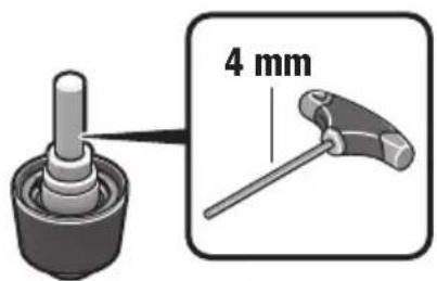
During machining, the guide roller must always be in contact with the workpiece.
Firstly remove the switched-on power tool from the workpiece and then switch it off. Otherwise, the workpiece and application tools may be damaged.
If power tool vibrations increase significantly, check the setting parameters for the respective application material and the condition of the application tool.
WARNING
Danger of injury from chippings.
Always keep your hands, clothing
etc. away from chippings. Do not attempt to remove the application tool when still rotating. This can lead to serious injuries.
WARNING
Danger of injury from sharp edges of the milling head. Do not touch
the milling head.
WARNING
Danger of burning. The application tool can become hot during opera-
tion. Allow the application tool to cool down:
- after placing the power tool down
- prior to tool changing.
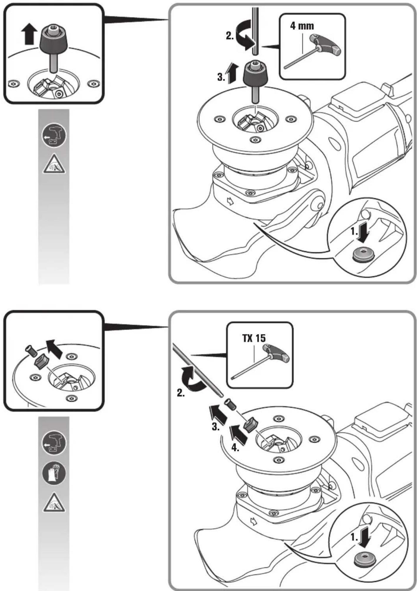
Rotate or turn around the eightfold heads as required. Please note that milling head, guide rollers and indexable inserts may vary depending on the application. Only use accessories approved for the application.
When machining bevels and radii, pay attention that the correct speed stage is set dependent of the material.
Various materials can be subject to hardening at the edges due to heating, plasma or laser cutting. This can lead to very high deviations from the specified reference values.
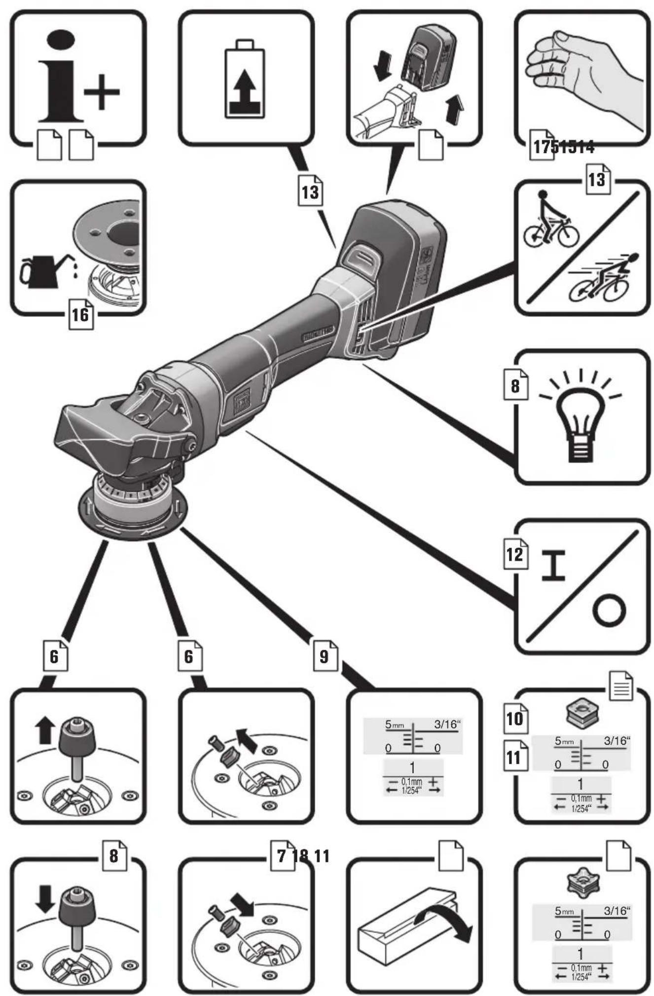
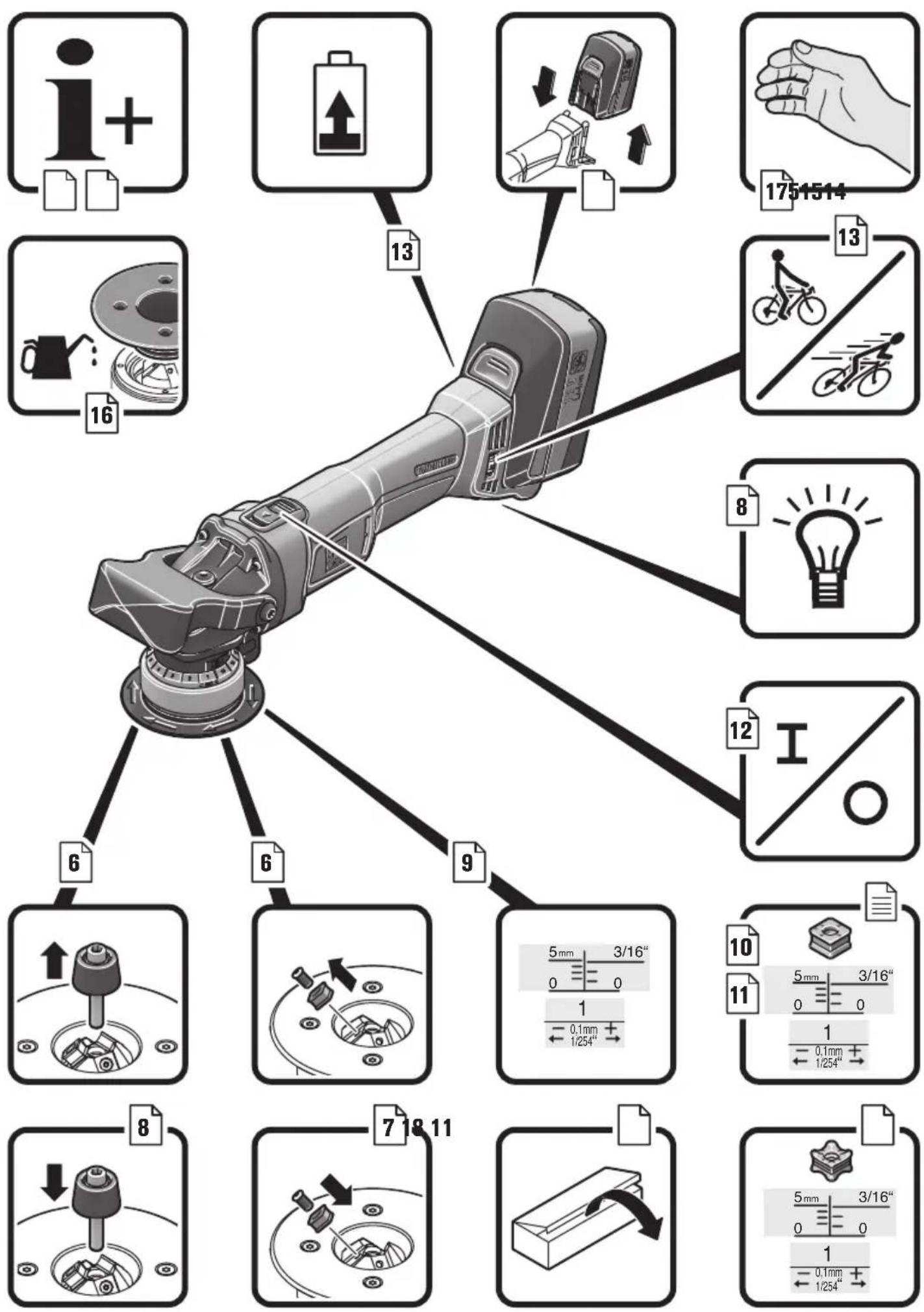
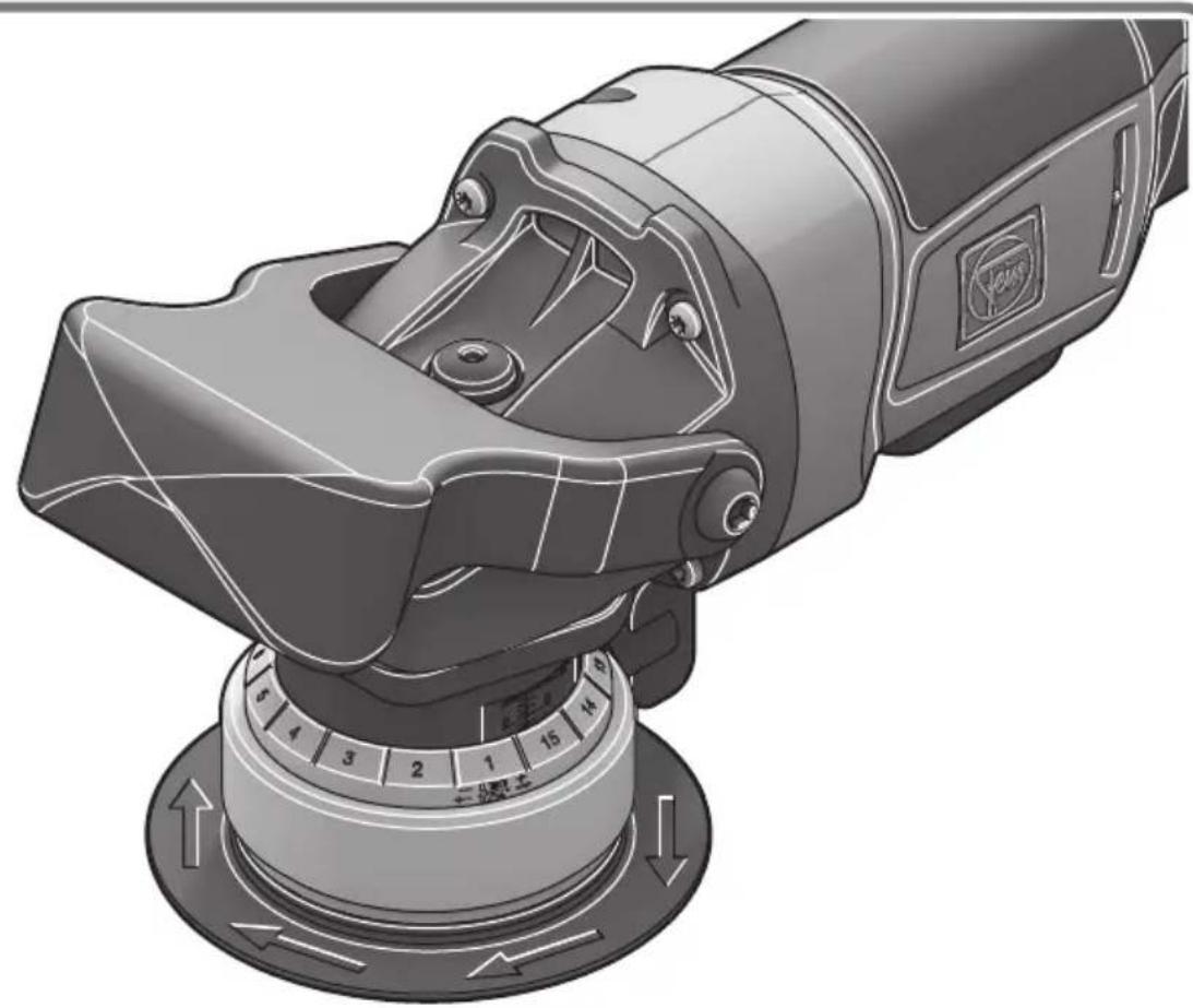
Setting the bevel height (see page 10/11)
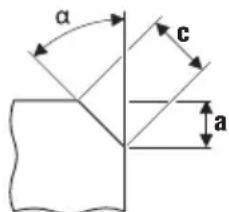
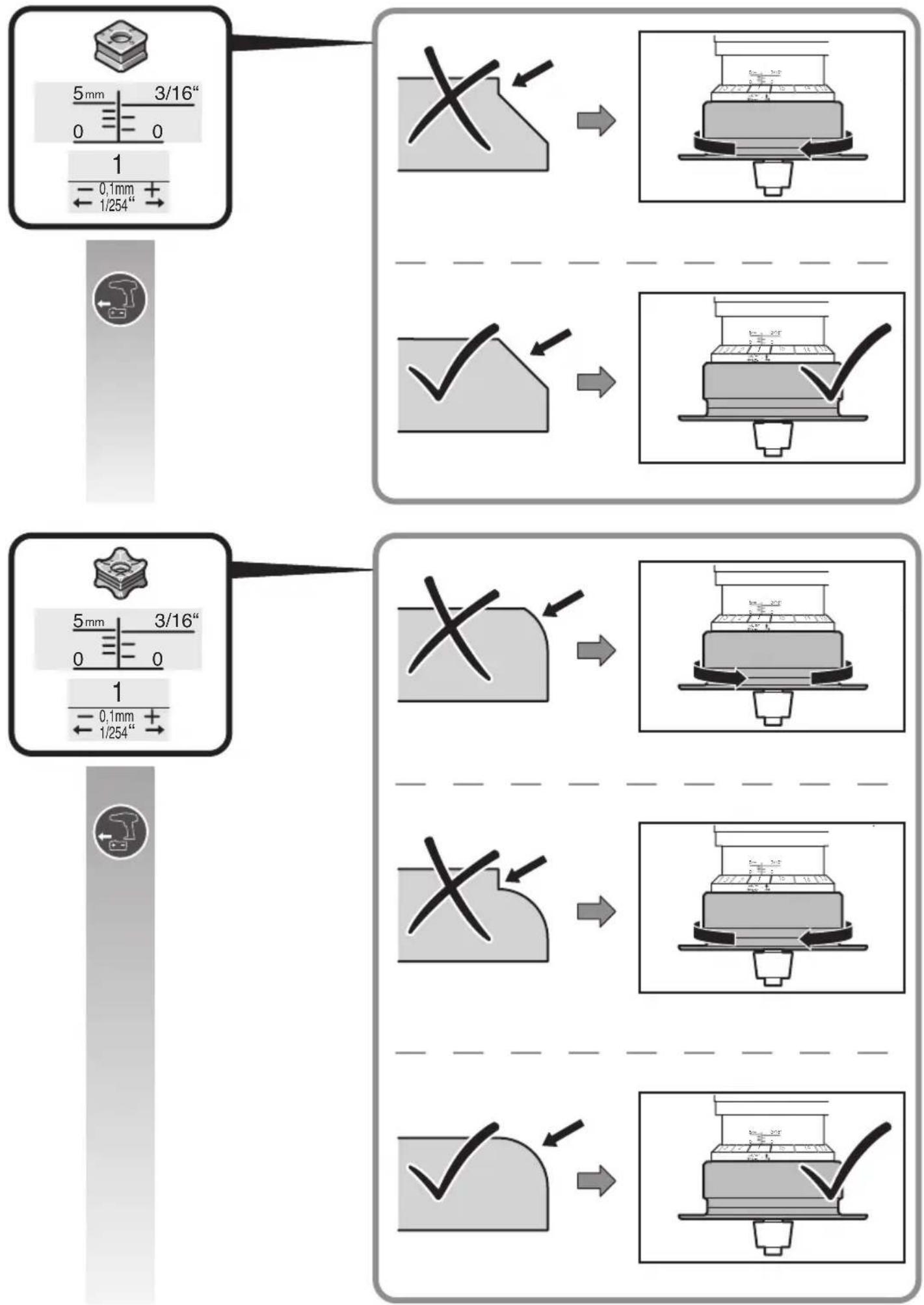
Use indexable inserts for bevels, which are available as accessories. Set the bevel height "a" via the setting dimension at the guide plate. Make a test run. As the scale has a tolerance of approx. ± 1 mm (approx. 1/32"), readjustment may be necessary. Readjustment is made using the second scale (numbers 1 to 15) on the guide plate. The guide plate is adjusted by 0.1 mm (1/254") per digit. The maximum, material-dependent setting dimension and the recommended speed stage can be found in the following two tables.
Setting the radius dimension (see page 11)
Use indexable inserts for radii, which are available as accessories. The setting dimension of the guide plate must be adapted to the respective radius. For setting dimension values, please refer to the respective accessory. For the material-dependent speed stage, please refer to the two tables below.
| Max. setting dimension (applies for 45° bevel and radius) [mm] [inch] | Recommended speed stage | ||
| Aluminium 3.5 | 2/16 6 | ||
| Steel 400 N/mm ^2 | 3.5 2/16 6 | ||
| Steel 600 N/mm ^2 | 2.8 2/16 4-5 | ||
| Steel 900 N/mm ^2 | 2.8 2/16 4-5 | ||
| Stainless steel | 1.4 1/16 1-3 | ||
The specified values are empirical values and cannot be guaranteed.
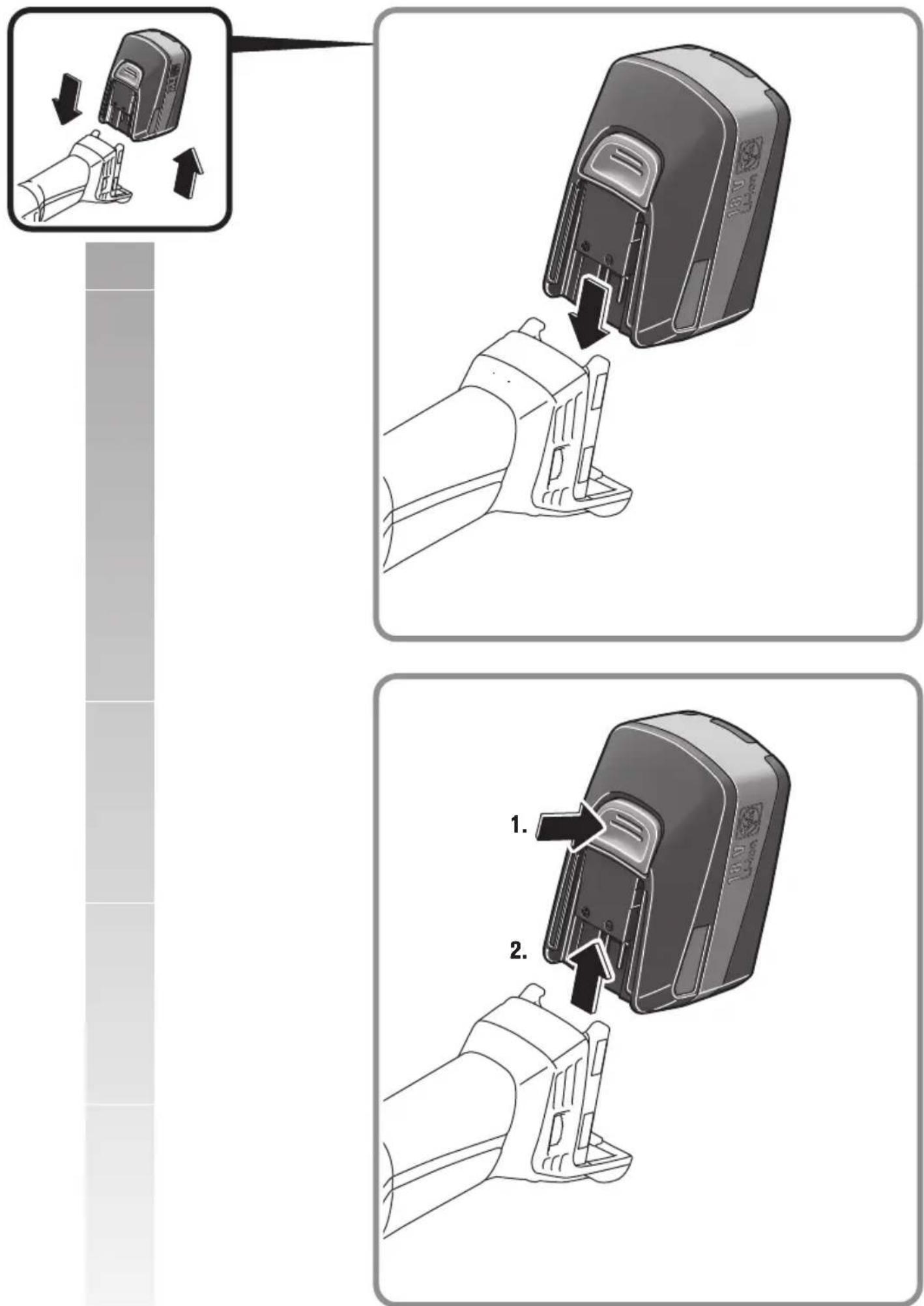
Handling the battery.
Store, operate and charge the battery only using FEIN battery chargers within the battery operating-temperature range between 5 °C – 45 °C (41 °F – 113 °F). At the beginning of the charging procedure, the battery temperature must be within the battery operating-temperature range.
| LED indicator | Meaning Activity | |
| 1 – 4 green LED | Percentage of charge condition | Operation |
| Continuous red light | Battery is almost empty | Charge battery |
| Red flashing light | Battery is not ready for operation | Bring the battery into the battery operating-temperature range, then charge |
The real percentage of the battery charge condition is only indicated when the power tool motor is stopped. The electronics automatically switch off the motor prior to the battery being deep discharged.
Repair and customer service.


When working metal under extreme operating conditions, it is possible for conductive dust to settle in the interior of the power
tool. Blow out the interior of the power tool via the ventilation slots frequently with dry and oil-free compressed air.
Clean and lubricate the thread of the height adjustment on the guide plate as required. Unscrew the guide plate and turn out the guide-plate holder. Clean the thread on both sides and apply oil.
Products that have come into contact with asbestos may not be sent in for repair. Dispose of products contaminated with asbestos according to the applicable country-specific regulations for such disposal.
The current spares parts list for this power tool can be found on our website at www.fein.com.
If required, you can change the following parts yourself:
application tools, guide roller, battery
Warranty and liability.
The warranty for the product is valid in accordance with the legal regulations in the country where it is marketed. In addition, FEIN also provides a guarantee in accordance with the FEIN manufacturer's warranty declaration.
The delivery scope of your power tool may include only a part of the accessories described or shown in this Instruction Manual.
Declaration of conformity.
FEIN declares itself solely responsible for this product conforming with the relevant provisions given on the last page of this Instruction Manual.
Technical documents at: C. & E. Fein GmbH, D-73529 Schwäbisch Gmünd
Environmental protection, disposal.
Packaging, worn out power tools and accessories should be sorted for environmental-friendly recycling. Dispose of batteries only when discharged.
For batteries that are not completely discharged, insulate the terminals with tape as a protective measure against short-circuiting.
Selection of accessories (see page 19).
Use only original FEIN accessories. The accessories must be intended for the power tool type.
A Indexable insert for bevels
B Indexable insert for radii
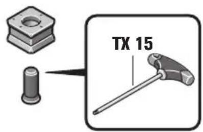
C Guide roller
Miljøvern, deponering.
The Ground Truth image displays a single, solid horizontal line. According to Rule 2 (UNDERSCORE & LINE RULES), this is a stylistic or background line, not a placeholder underscore. Therefore, the OCR result must ignore it and output nothing or only meaningful text. The provided OCR content is "____", which consists of four underscores. This is an incorrect interpretation of the line as a placeholder, violating the rule that stylistic lines must be ignored. The OCR has hallucinated underscores where none should exist based on the GT's visual context. Hence, the OCR result is inconsistent with the Ground Truth.
The Ground Truth image displays a single, solid horizontal line. According to Rule 2 (UNDERSCORE & LINE RULES), this is a stylistic or background line, not a placeholder underscore. Therefore, the OCR result must ignore it and output nothing or only meaningful text. The provided OCR content is "____", which consists of four underscores. This is an incorrect interpretation of the line as a placeholder, violating the rule that stylistic lines must be ignored. The OCR has hallucinated underscores where none should exist based on the GT's visual context. Hence, the OCR result is inconsistent with the Ground Truth.
The Ground Truth image displays a single, solid horizontal line. According to Rule 2 (UNDERSCORE & LINE RULES), this is a stylistic or background line, not a placeholder underscore. Therefore, the OCR result must ignore it and output nothing or only meaningful text. The provided OCR content is "____", which consists of four underscores. This is an incorrect interpretation of the line as a placeholder, violating the rule that stylistic lines must be ignored. The OCR has hallucinated underscores where none should exist based on the GT's visual context. Hence, the OCR result is inconsistent with the Ground Truth.
The Ground Truth image displays a single, solid horizontal line. According to Rule 2 (UNDERSCORE & LINE RULES), this is a stylistic or background line, not a placeholder underscore. Therefore, the OCR result must ignore it and output nothing or only meaningful text. The provided OCR content is "____", which consists of four underscores. This is an incorrect interpretation of the line as a placeholder, violating the rule that stylistic lines must be ignored. The OCR has hallucinated underscores where none should exist based on the GT's visual context. Hence, the OCR result is inconsistent with the Ground Truth.
The Ground Truth image displays a single, solid horizontal line. According to Rule 2 (UNDERSCORE & LINE RULES), this is a stylistic or background line, not a placeholder underscore. Therefore, the OCR result must ignore it and output nothing or only meaningful text. The provided OCR content is "____", which consists of four underscores. This is an incorrect interpretation of the line as a placeholder, violating the rule that stylistic lines must be ignored. The OCR has hallucinated underscores where none should exist based on the GT's visual context. Hence, the OCR result is inconsistent with the Ground Truth.
China RoHS Status Certificate
中国 RoHS 认证概况
Table of Toxic and Hazardous Substances/Elements and their Content as required by China's Management Methods for Controlling Pollution by Electronic Information Products
有毒有害物质 / 成分及其含量表
Director of Quality Specialist Power/Control Management


- Translation of the Original Instructions.
- Symbols, abbreviations and terms used.
- For your safety.
- WARNING
- Intended use of the power tool:
- Special safety instructions.
- Do not use accessories that require liquid coolants.
- Kickback and related warnings
- Further safety warnings
- Hand/arm vibrations
- Emission values for vibration
- Handling hazardous dusts
- Operating Instructions.
- Danger of injury from chippings.
- Danger of injury from sharp edges of the milling head. Do not touch
- Danger of burning. The application tool can become hot during opera-
- Setting the bevel height (see page 10/11)
- Setting the radius dimension (see page 11)
- Handling the battery.
- Repair and customer service.
- If required, you can change the following parts yourself:
- Warranty and liability.
- Declaration of conformity.
- Environmental protection, disposal.
- Selection of accessories (see page 19).
- Miljøvern, deponering.
- China RoHS Status Certificate
- 中国 RoHS 认证概况
Brand : Fein
Model : AKFH 185 Select
Category : Milling machine