
SAB00100 - Sauna HARVIA - Free user manual and instructions
Find the device manual for free SAB00100 HARVIA in PDF.
| Product type | Door control for sauna |
| Brand | Harvia |
| Model | SAB00100 |
| Power supply dimensions | 85 x 85 x 40 mm |
| Door sensor dimensions | 55 x 10 x 10 mm |
| Push button dimensions | 55 x 55 x 15 mm |
| Operating voltage | 230 V ~ 50/60 Hz |
| Protection degree | IP X4 |
| Permissible ambient temperature | -40 °C to +40 °C |
| Main functions | Door monitoring, activation/deactivation of remote start |
| Compatibility | Pro series sauna controls, home.com4, Xafir, Xenio |
| Power supply | 230 V ~, cable 3 x 1.5 mm² |
| Sensor cable length | 3 m (silicone) |
| Push button cable length | 4 m (silicone) |
| Delivery contents | Power supply, illuminated push button, door sensor, magnet, magnet holder for glass 8/10 mm, mounting instructions |
| Installation | By a qualified electrician |
| Maintenance | No maintenance required |
| Safety instructions | Proper use, instructions for installer and user, do not use by children under 8 years without supervision |
| General information | Manual available at www.sentiotec.com/downloads |
Frequently Asked Questions - SAB00100 HARVIA
User questions about SAB00100 HARVIA
0 question about this device. Answer the ones you know or ask your own.
Ask a new question about this device
Download the instructions for your Sauna in PDF format for free! Find your manual SAB00100 - HARVIA and take your electronic device back in hand. On this page are published all the documents necessary for the use of your device. SAB00100 by HARVIA.
USER MANUAL SAB00100 HARVIA
Door monitoring system
INSTRUCTIONS FOR INSTALLATION AND USE English
natural_image
Technical line drawing of an electronic device housing with a close-up view of its internal components (no text or symbols)EN
DE
FR
IT
NL
cs
PL
PT
SV
FI
RU
Table of Contents
1. About this instruction manual 3
2. Important information for your safety 4
2.1. Intended use 4
2.2. Safety information for the installer 4.
2.3. Safety information for the user 5
3. Product description 6
3.1. Scope of delivery .6
3.2. Product features .6
4. Installation 6
4.1. Installing the power supply unit 6.
4.2. Mounting the door sensor .7
4.3. Mounting the magnet 8
4.4. Installing the button 8
5. Electrical connection 9
6. Connection diagram 9
6.1. Connection to Pro series (Pro B2/3, Pro C2/3, Pro D) 10
6.2. Connection to home.com4 10
6.3. Connection to Xenio (CX110C, CX170)....11
6.4. Connection to Xafir (CS110C, CS170) 11
7. Operation 12
8. Maintenance 12
9. Disposal 12
10. Technical data 13
1. About this instruction manual
Read these instructions for installation and use carefully and keep them within reach of the device. This ensures that you can refer to information on safety and operation at any time.
These installation and operating instructions can also be found in the downloads section of our website: www.sentiotec.com/downloads.
Symbols used for warning notices
In these instructions for installation and use, a warning notice located next to an activity indicates that this activity poses a risk. Always observe the warning notices. This prevents damage to property and injuries, which in the worst case may be fatal.
The warning notices contain keywords, which have the following meanings:
DANGER!
Serious or fatal injury will occur if this warning notice is not observed.
WARNING!
Serious or fatal injury can occur if this warning notice is not observed.

CAUTION!
Minor injuries can occur if this warning notice is not observed.
NOTE!
This keyword is a warning that damage to property can occur.
Other symbols
This symbol indicates tips and useful information.
Read the operating instructions
2. Important information for your safety
The door monitoring system has been produced in accordance with the applicable safety regulations. However, hazards may arise during use. Therefore adhere to the following safety information and the specific warning notices in the individual chapters.
2.1. Intended use
The door monitoring system monitors the sauna door when using the remote operation function.
A sauna heater controlled by the remote start function of the sauna control unit must pass the combustion test as specified in EN 60335-2-53 paragraph 19.101. If the heater does not meet this requirement, an appropriate safety precaution must be taken (for example: safety switch-off or door monitoring)
Any use exceeding this scope is considered improper use. Improper use can result in damage to the product, severe injuries or death.
2.2. Safety information for the installer
- Installation may only be performed by a qualified electrician or similarly qualified person.
- Installation and connection of the door monitoring system may only be performed when the power supply is disconnected.
- Observe the installation instructions for the sauna control unit used.
- Also comply with the regulations applicable at the installation location.
- For your own safety, consult your supplier in the event of problems that are not explained in sufficient detail in the installation instructions.
2.3. Safety information for the user
- The door monitoring system may not be used by children under 8 years old.
- The door monitoring system may be used by children over 8 years old, by persons with limited psychological, sensory or mental capabilities or by persons with lack of experience/knowledge only under the following conditions:
– They are supervised.
– They have been shown how to use the device safely and are aware of the hazards that could occur.
- Children may not play with the door monitoring system.
- Observe the operating instructions for the sauna control unit used.
- For your own safety, consult your supplier in the event of problems that are not described in sufficient detail in the user instructions.
3. Product description
3.1. Scope of delivery
- Door monitoring system power supply unit
- Illuminated button with connection cable
- Door sensor with connection cable, double-sided adhesive tape
- Magnet
- Door magnet holder for 8 and 10 mm glass
- Assembly instructions
3.2. Product features
The door monitoring system monitors the closed sauna door when the remote start is activated. If the sauna door is opened during “Standby for remote control”, the remote start function is cancelled.
Compatible sauna control units: Pro series, home.com4, Xafir, Xenio
4. Installation
During installation observe the technical data on Page 13:
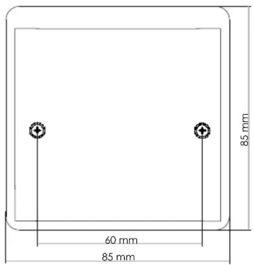
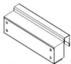
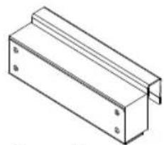
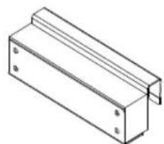
4.1. Installing the power supply unit
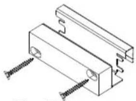
- Fasten the power supply unit 1 of the door monitoring system near the sauna control using the screws provided (power supply unit - for 2-part control units)
- Cables which are laid in the cabin wall must be temperature-resistant up to 150 °C.
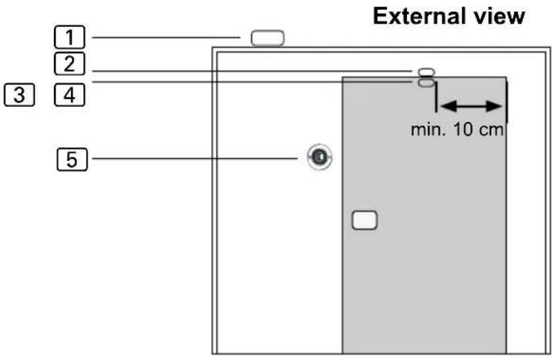
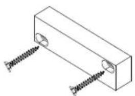
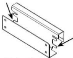
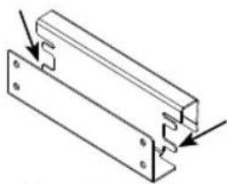
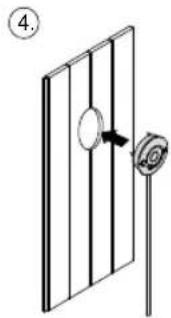
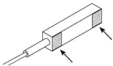
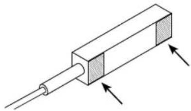
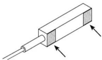
4.2. Mounting the door sensor
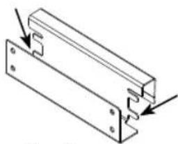
Fasten the door sensor ② outside the cabin near the sauna door:
Observe the minimum distance of 10 cm from the door hinge.
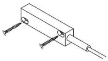
- For a wooden sauna cabin:
▶ Use the wood screws supplied (Fig. A).
- For a glass surface:
▶ Use the double-sided adhesive tape (Fig. B). Cut the adhesive tape provided into two equally sized pieces and stick the pieces to the back of the door sensor as shown in Fig. B.
natural_image
Technical line drawing of a mechanical component with two screws inserted (no text or symbols)Fig. A Fig. B

natural_image
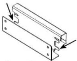
Diagram of a rectangular electronic component with two arrows indicating direction (no text or symbols)
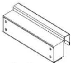
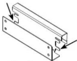
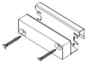
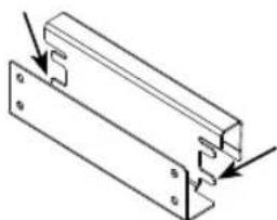
4.3. Mounting the magnet
Fasten the magnet ③ to the sauna door so that it is flush with the sensor.
Make sure the distance to the door sensor is correct to ensure that it works properly
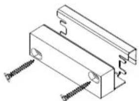
- On a wooden door:
▶ Use the wood screws supplied (Fig. C).
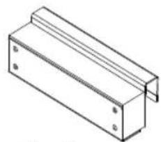
- For a glass door, use the door magnet holder 4.
Depending on the distance to the door sensor, the following installations are possible:
The magnet is placed inside the holder (Fig. D). Fix the magnet by bending the retaining tabs into the recesses with a screwdriver.
▶ Alternatively, screw the magnet onto the outside of the door magnet holder (Fig. E).
natural_image
Isometric line drawing of a rectangular block with two screws inserted (no text or symbols)Fig. C
natural_image
Isometric line drawing of a rectangular metal bracket with mounting holes (no text or symbols)Fig. D
natural_image
Technical line drawing of a mechanical bracket assembly with mounting holes and fasteners (no text or symbols)Fig. D

natural_image
Technical line drawing of a mechanical bracket with screws inserted (no text or symbols)Fig. E
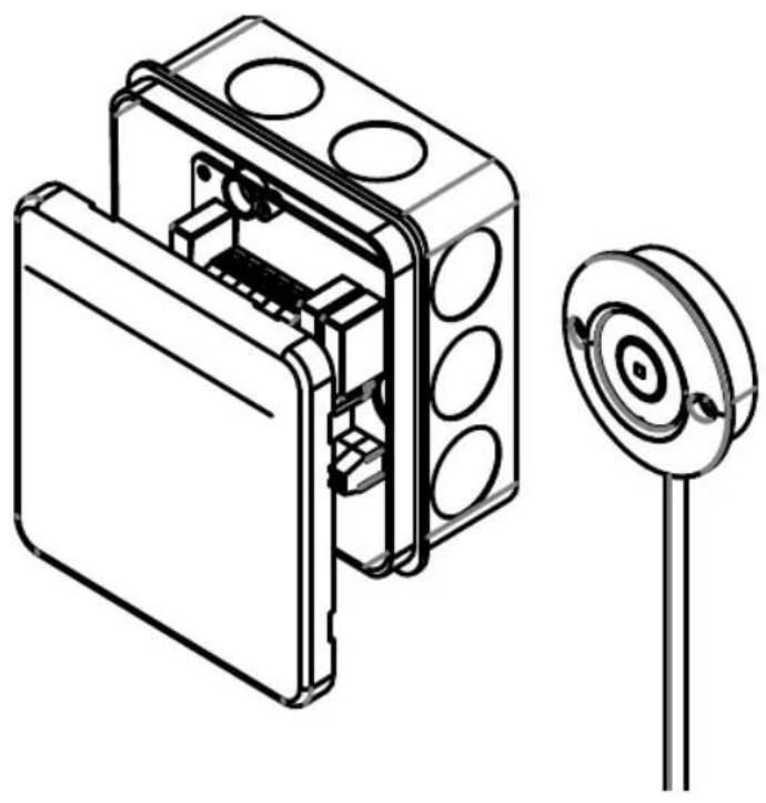
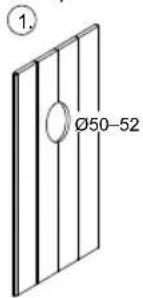
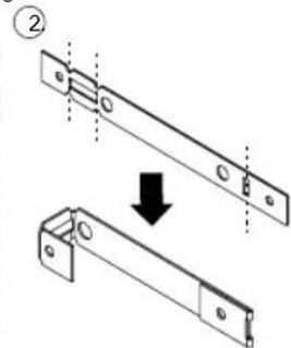
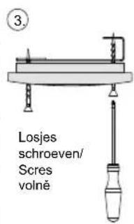
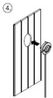
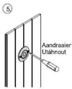
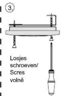
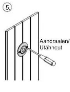
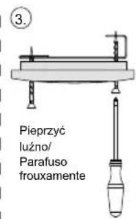
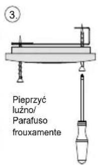
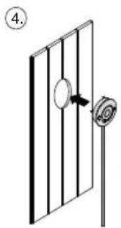
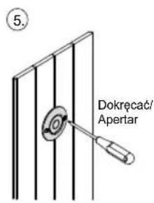
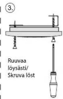
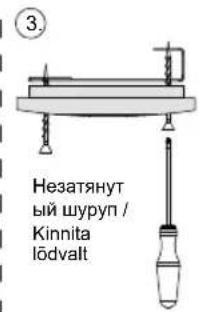
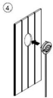
4.4. Installing the button
The door monitoring button 5 can be installed on the surface or flush-mounted (Fig. F)
Flush mounted / Unterputz Montage
natural_image
Technical diagram showing two mechanical components with a downward arrow indicating assembly or transformation (no text or symbols present)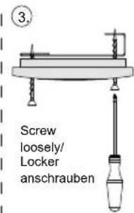
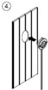
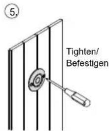
Fig. F
5. Electrical connection
Observe the following points when connecting the power to the door monitoring system:
- Guide the connection cables through the cable bushings. Drill the holes as small as possible (e.g. 2 mm flat blade screwdriver) to maintain the humidity protection.
- Observe the installation instructions for the sauna control unit used. Jumpers may have to be placed and functions enabled in the technician menu.
6. Connection diagram
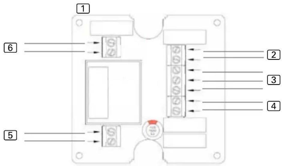

① Power supply unit
2 Door sensor
3 Button (red = LED+, white = SW3, blue = SW4)
4 Remote start switch / remote start system
5 Power supply 230 V\~ 50 /60 Hz
6 Sauna control unit remote start contacts (polarity not relevant)
6.1. Connection to Pro series (Pro B2/3, Pro C2/3, Pro D)
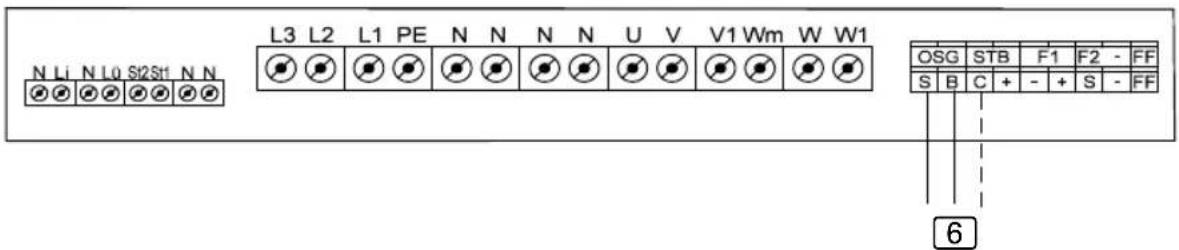
6 Connection to S/B....Remote start of sauna operation / user program 1 Connection to C/B....Remote start of combination mode / user program 2
6.2. Connection to home.com4
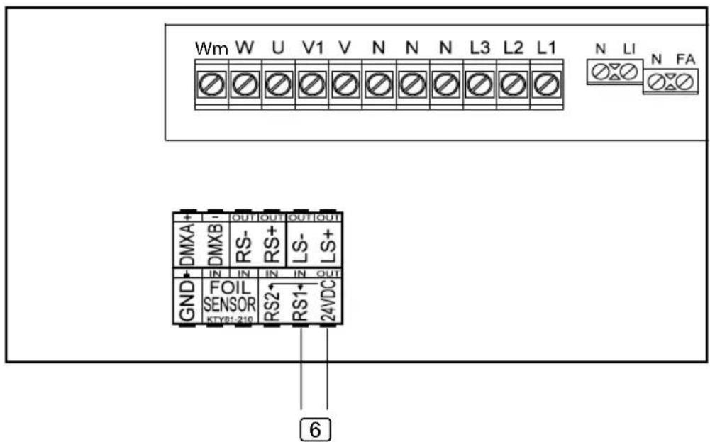
6 Connection to RS1/24VDC....Remote start
- Make the setting in the technician menu under menu item Mode RS1.
6.3. Connection to Xenio (CX110C, CX170)
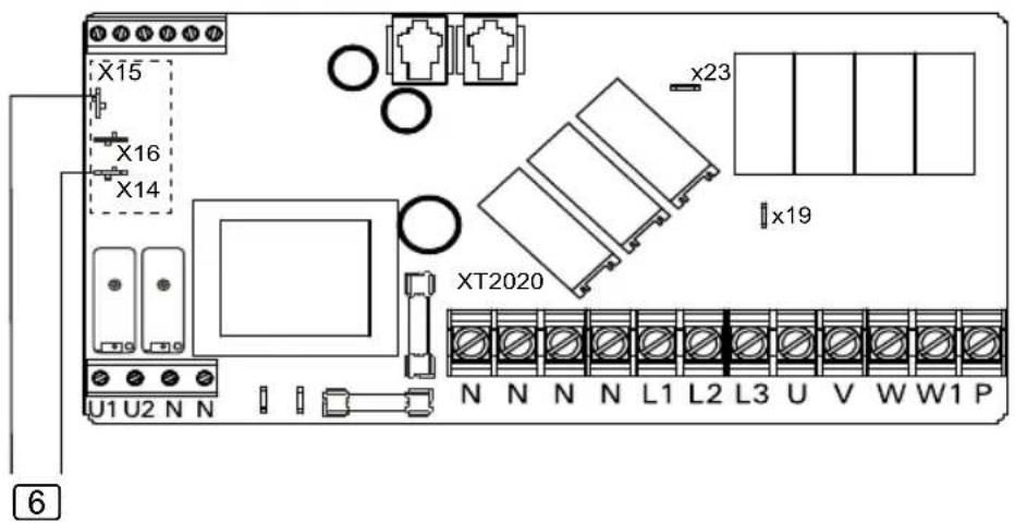
• PIN X15 and X16 must be bridged.
- The SAFE function must be set to ON in the settings.
6.4. Connection to Xafir (CS110C, CS170)
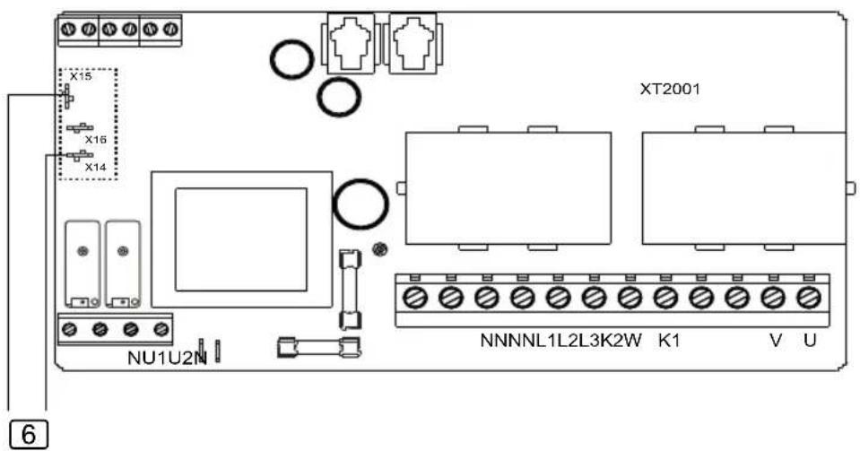
• PIN X15 and X16 must be bridged.
- The SAFE function must be set to ON in the settings.

7. Operation
Observe the operating instructions for the sauna control unit used.
- Make sure that no flammable objects have been placed on the sauna heater.
- Close the sauna door.
- Switch the sauna control unit to remote start in the desired operating mode. Observe the operating instructions for the sauna control unit used.
▶ The activated remote start is displayed.
- Activate the door monitoring button.
▶ The sauna control unit is then ready to be started and stopped using a remote start signal.
If the sauna door is opened when the remote start function is activated, the remote start function goes out and the sauna control unit goes into standby mode.
8. Maintenance
The device is maintenance-free.
9. Disposal
- Please dispose of packaging materials in accordance with the applicable disposal regulations.
- Used units contain reusable materials as well as hazardous substances. Therefore, do not dispose of your used unit with household waste, but rather do so in accordance with the locally applicable regulations.
10. Technical data
Ambient conditions
Ambient temperature: -40 °C to +40 °C
Protection class (protected against splashing water): IP X4
Power supply unit
Dimensions: 85 x 85 x 40 mm
Operating voltage: 230 V 50/60 Hz AC
Door sensor
Dimensions: 55 x 10 x 10 mm
Installation opening: ∅ 50 x 13 mm
Connection cable 3 m - 2 x 0.5 mm ^4 , silicone
Illuminated button
Dimensions: 55 x 55 x 15 mm
Diameter of installation opening: 50 mm
Connection cable 4 m - 3 x 0.5 mm ^2 , silicone
Connection cables
Power supply: 3 × 1.5 mm^2
Remote start switch or remote start system: 2 x 0.5 mm ^4
Remote start signal from sauna control unit: 2 x 0.5 mm ^4
Global:
www.harvia.fi
Tel. +358 207 464 000
Central
www.sentiotec.com
Europe
Türüberwachung
natural_image
Technical line drawing of a mechanical assembly with internal components and a circular component (no text or symbols)DE
Inhaltsverzeichnis
natural_image
Technical line drawing of a mechanical component with two screws attached (no text or symbols)Abb. A Abb. B

natural_image
Pure diagram of a rectangular block with two arrows pointing outward from its ends (no text or symbols)4.3. Montage Magnet
natural_image
Isometric line drawing of a rectangular block with two screws inserted (no text or symbols)Abb. C

natural_image
Isometric line drawing of a rectangular metal bracket with mounting holes (no text or symbols)Abb. D
natural_image
Technical line drawing of a mechanical bracket assembly with mounting holes and fasteners (no text or symbols)Abb. D

natural_image
Technical line drawing of a mechanical bracket with screws inserted (no text or symbols)Abb. E
4.4. Montage Taster
natural_image
Technical diagram showing two mechanical components with a downward arrow indicating transformation (no text or symbols present)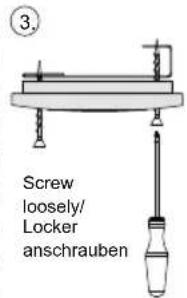
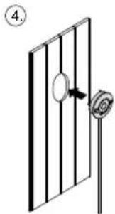
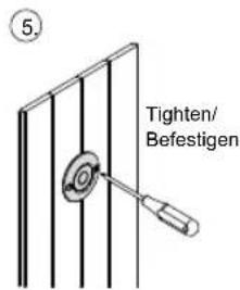
Fig. F
natural_image
Technical line drawing of an electronic device housing with a close-up of its internal components and a circular component (no text or symbols)FR
Table des matières
1. Concernant ces instructions 3
natural_image
Technical line drawing of a mechanical assembly with screws inserted (no text or symbols)
natural_image
Pure technical diagram of a rectangular block with internal components and directional arrows, no text or symbols present.Fig. A Fig. B
natural_image
Technical line drawing of a rectangular bracket with two screws inserted (no text or symbols)Fig. C

natural_image
Isometric line drawing of a rectangular metal bracket with mounting holes (no text or symbols)Fig. D
natural_image
Technical line drawing of a mechanical bracket with mounting holes and internal features (no text or symbols)Fig. D

natural_image
Technical line drawing of a mechanical bracket with screws inserted (no text or symbols)Fig. E
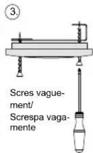
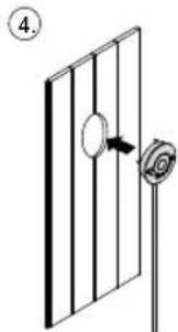
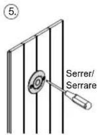
Fig. F
natural_image
Technical line drawing of a mechanical assembly with internal components and a circular component (no text or symbols)IT
Indice
natural_image
Technical line drawing of a mechanical assembly with screws and a rectangular block (no text or symbols)
natural_image
Diagram of a rectangular electronic component with two leads and directional arrows indicating force or direction (no text or symbols)Fig. A Fig. B
natural_image
Isometric line drawing of a rectangular block with two circular holes and four evenly spaced screws attached (no text or symbols)Fig. C

natural_image
Isometric line drawing of a rectangular metal bracket with mounting holes (no text or symbols)Fig. D

natural_image
Technical line drawing of a mechanical bracket assembly with mounting holes and fasteners (no text or symbols)Fig. D
natural_image
Technical line drawing of a mechanical bracket with screws inserted (no text or symbols)Fig. E
natural_image
Technical diagram showing two mechanical components with a downward arrow indicating assembly or transformation (no text or symbols present)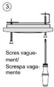
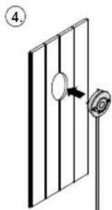
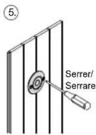
Fig. F
natural_image
Technical line drawing of a mechanical assembly with internal components and a circular component (no text or symbols)NL
Inhoudsopgave
natural_image
Technical line drawing of a mechanical assembly with screws inserted (no text or symbols)Afb. A Afb. B

natural_image
Diagram of a rectangular electronic component with two arrows indicating direction (no text or symbols)4.3. Montage magneet
natural_image
Isometric line drawing of a rectangular block with two circular holes and two screws attached (no text or symbols)Afb. C
natural_image
Isometric line drawing of a rectangular metal bracket with four corner holes (no text or symbols)Afb. D

natural_image
Technical line drawing of a mechanical bracket with mounting holes and internal cutouts (no text or symbols)Afb. D

natural_image
Technical line drawing of a mechanical bracket with screws and mounting holes (no text or symbols)Afb. E
4.4. Montage toets
natural_image
Technical line drawing of a mechanical assembly with internal components and a circular component (no text or symbols)cs
Obsah
natural_image
Technical line drawing of a mechanical assembly with screws and a shaft (no text or symbols)Obr. A Obr. B

natural_image
Diagram of a rectangular block with a rod and two arrows pointing outward (no text or symbols)
4.3. Montáž magnetu
natural_image
Isometric line drawing of a rectangular block with two screws inserted (no text or symbols)Obr. C

natural_image
Isometric line drawing of a rectangular metal bracket with mounting holes (no text or symbols)Obr. D
natural_image
Technical line drawing of a mechanical bracket assembly with mounting holes and internal cutouts (no text or symbols)Obr. D
natural_image
Technical line drawing of a mechanical bracket with screws inserted (no text or symbols)Obr. E
natural_image
Technical line drawing of a mechanical assembly with internal components and a circular component (no text or symbols)PL
SPIS TREŚCI
natural_image
Technical line drawing of a mechanical assembly with screws and a rectangular block (no text or symbols)Rys. A Rys. B

natural_image
Pure diagram of a rectangular block with a rod and two arrows indicating direction (no text or symbols)
4.3. Montaż magnesu
natural_image
Isometric line drawing of a rectangular block with two circular holes and four screws inserted (no text or symbols)Rys. C

natural_image
Isometric line drawing of a rectangular metal bracket with four corner holes (no text or symbols)Rys. D
natural_image
Technical line drawing of a mechanical bracket with mounting holes and fasteners (no text or symbols)Rys. D
natural_image
Technical line drawing of a mechanical bracket with screws inserted (no text or symbols)Rys. E
natural_image
Technical line drawing of a mechanical assembly with internal components and a circular component (no text or symbols)PT
Índice
1. Sobre este manual 3
natural_image
Technical line drawing of a mechanical component with two screws inserted (no text or symbols)Fig. A Fig. B
natural_image
Diagram of a rectangular electronic component with two arrows indicating direction (no text or symbols)
natural_image
Isometric line drawing of a rectangular block with two screws inserted (no text or symbols)Fig. C
natural_image
Isometric line drawing of a rectangular metal bracket with mounting holes (no text or symbols)Fig. D

natural_image
Technical line drawing of a mechanical bracket with mounting holes and internal features (no text or symbols)Fig. D

natural_image
Technical line drawing of a mechanical bracket with screws inserted (no text or symbols)Fig. E
natural_image
Technical line drawing of a mechanical housing with internal components and a separate circular component (no text or symbols)SV
natural_image
Technical line drawing of a mechanical component with two screws inserted (no text or symbols)Bild A Bild B

natural_image
Diagram of a rectangular electronic component with two arrows indicating direction (no text or symbols)
natural_image
Isometric line drawing of a rectangular block with two circular holes and two screws attached (no text or symbols)Bild C

natural_image
Isometric line drawing of a rectangular metal bracket with mounting holes (no text or symbols)Bild D

natural_image
Technical line drawing of a mechanical bracket with mounting holes and mounting holes (no text or symbols)Bild D

natural_image
Technical line drawing of a mechanical bracket with screws and mounting holes (no text or symbols)Bild E

natural_image
Technical line drawing of a mechanical assembly with internal components and a circular component (no text or symbols)FI
Sisällys
natural_image
Technical line drawing of a mechanical assembly with two screws and a rectangular block (no text or symbols)Kuva A Kuva B
natural_image
Diagram of a rectangular electronic component with two leads and a shaded section, no text or symbols presentnatural_image
Isometric line drawing of a rectangular block with two screws inserted (no text or symbols)Kuva C
natural_image
Isometric line drawing of a rectangular metal bracket with mounting holes (no text or symbols)Kuva D

natural_image
Technical line drawing of a mechanical bracket assembly with mounting holes and fasteners (no text or symbols)Kuva D

natural_image
Technical line drawing of a mechanical bracket with screws inserted (no text or symbols)Kuva E
natural_image
Technical line drawing of a mechanical assembly with internal components and a circular component (no text or symbols)RU
Содержание
natural_image
Technical line drawing of a mechanical assembly with screws and a shaft (no text or symbols)Рис. А Рис. В
natural_image
Diagram of a rectangular electronic component with a shaft and housing, showing directional arrows (no text or symbols)RU
4.3. Монтаж магнита
natural_image
Isometric line drawing of a rectangular block with two screws attached (no text or symbols)Рис. С
natural_image
Isometric line drawing of a rectangular metal bracket with four corner holes (no text or symbols)Рис. D
natural_image
Technical line drawing of a mechanical bracket with mounting holes and internal cutouts (no text or symbols)Рис. D

natural_image
Technical line drawing of a mechanical bracket with screws inserted (no text or symbols)Рис. Е
4.4. Монтаж кнопки
natural_image
Simple line drawing of a door with a scroll wheel and an arrow indicating direction (no text or symbols)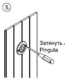
Рис. F


- Door monitoring system
- Table of Contents
- About this instruction manual 3
- Important information for your safety 4
- Product description 6
- Installation 6
- Electrical connection 9
- Connection diagram 9
- Operation 12
- Maintenance 12
- Disposal 12
- Technical data 13
- About this instruction manual
- Symbols used for warning notices
- DANGER!
- WARNING!
- CAUTION!
- NOTE!
- Other symbols
- Important information for your safety
- Intended use
- Safety information for the installer
- Safety information for the user
- Product description
- Scope of delivery
- Product features
- Installation
- Installing the power supply unit
- Mounting the door sensor
- Mounting the magnet
- Installing the button
- Electrical connection
- Connection diagram
- Connection to Pro series (Pro B2/3, Pro C2/3, Pro D)
- Connection to home.com4
- Connection to Xenio (CX110C, CX170)
- Connection to Xafir (CS110C, CS170)
- Operation
- Maintenance
- Disposal
- Technical data
- Ambient conditions
- Power supply unit
- Door sensor
- Illuminated button
- Connection cables
- Türüberwachung
- Inhaltsverzeichnis
- Montage Magnet
- Montage Taster
- Table des matières
- Concernant ces instructions 3
- Indice
- Inhoudsopgave
- Montage magneet
- Montage toets
- Obsah
- Montáž magnetu
- SPIS TREŚCI
- Montaż magnesu
- Índice
- Sobre este manual 3
- Sisällys
- Содержание
- Монтаж магнита
- Монтаж кнопки
Brand : HARVIA
Model : SAB00100
Category : Sauna