
Fenix SACF10 - Sauna HARVIA - Free user manual and instructions
Find the device manual for free Fenix SACF10 HARVIA in PDF.


| Product Type | Sauna Heater |
| Brand | Harvia |
| Model | Fenix SACF10 |
| Power Output | 10.0 kW |
| Voltage | 400V 3N ~ 50Hz |
| Current | 14.4 A |
| Recommended Sauna Room Size | 8–14 m³ |
| Heating Element Type | Stainless steel |
| Control Type | Integrated electronic control |
| Stone Capacity | 20 kg |
| Dimensions (H x W x D) | 600 x 450 x 400 mm |
| Weight | 30 kg |
| Material | Powder-coated steel |
| Safety Features | Overheat protection, thermal cut-out |
| Installation Type | Wall-mounted |
| Protection Rating | IPX4 |
| Certification | CE, EAC |
| Manual Languages | EN, FI, SV, DE |
| Warranty | 2 years |
Frequently Asked Questions - Fenix SACF10 HARVIA
User questions about Fenix SACF10 HARVIA
0 question about this device. Answer the ones you know or ask your own.
Ask a new question about this device
Download the instructions for your Sauna in PDF format for free! Find your manual Fenix SACF10 - HARVIA and take your electronic device back in hand. On this page are published all the documents necessary for the use of your device. Fenix SACF10 by HARVIA.
USER MANUAL Fenix SACF10 HARVIA
VÄLJA SPRÅK FÖR DISPLAYEN 34
STÄLLA IN KLOCKSLAG OCH DATUM ...... 34
ANSLUTNING MELLAN ENHETER 34
PARNING AV ENHETER 35
VÄRMA UPP BASTUN 35
SETTING THE PRE-SETTING TIME - delayed heating 61
1. HARVIA FENIX CONTROL UNIT ...... 62
1.1. General 62
1.2. Technical Data 62
1.3. Configurations 63
2. INSTRUCTIONS FOR USE 63
2.1.General 63
2.1.1. Batteries 63
2.2. Function Menus in the Main Menu and Function Icons 63
2.3. Sauna Time Setup 64
2.4.Heater and Steamer Setup 64
2.4.1. Heater Setup 64
2.4.2. Steamer Setup 64
2.5. Colour Light and Light Setup 66
2.5.1. Colour Light Setup 66
2.5.2. Light Setup 67
2.6.Fan Setup 67
2.7. Week Timer 68
2.8.User Settings 70
2.9. Miscellaneous 71
2.9.1. Statistics 71
2.9.2. Curve Diagram 71
2.9.3. Adjust Current Time and Day ... 71
2.9.4.Device Pair-Up 71
2.9.5. Panel Power Settings 72
2.9.6. Additional Options and Settings 72
2.9.7. Detailed Version Info.... 72
2.9.8. Sensor Reading Adjustment ..... 72
2.9.9. Service Menu 72
a) Auxiliary Relay Function 72
b) Installed/Enabled Features 72
c) Heater Watts Setup 72
d) Steamer Watts Setup 72
e) Max On Time Setup 72
f) Load Factory Settings 72
2.10. Options 72
2.10.1. Calibrating the Touch Screen . 73
3. INSTRUCTIONS FOR INSTALLATION ..... 74
3.1. Installing the Wireless Control Unit ..... 74
3.2. Installing the Power Unit 76
3.2.1. Electrical Connections of Power Unit SACF150 for Heater 76
3.2.2. Electrical Connections of Power Unit SACF165S for Steamer/Heater ... 76
3.2.3. Electrical Installations of Power Unit SACF100 for Colour Light ..... 76
3.2.4. Installing the Radio Antenna .... 82
3.2.5. Installing the Temperature and Humidity Sensors 82
3.2.6. Resetting the Overheat Protector.... 83
Congratulations on choosing a Fenix control unit by Harvia!
With Fenix you can control all functions of your sauna via the user-prompting touch screen of a wireless control unit. You can control the temperature, humidity, colour lights, and all other aspects – from your couch. A novelty that makes it possible for you to enjoy your sauna in a variety of new ways!
INHALT
natural_image
Diagram showing two 3D rectangular components with diagonal lines and a shaded central area, enclosed within vertical grid lines (no text or symbols)natural_image
Technical line drawing of an electronic device chassis with connectors, modules, and wiring (no text or symbols)natural_image
Close-up of a hand using a screwdriver to apply white plastic or plastic components on a wall (no text or symbols visible)VÄLJA SPRÅK FÖR DISPLAYEN
natural_image
Two technical diagrams showing a grid-patterned panel with intersecting lines and a rectangular device (no text or symbols)natural_image
Technical line drawing of an electronic device chassis with labeled components and wiring (no text or symbols present)natural_image
Close-up of a hand using a screwdriver to apply plastic or plastic components on a wall (no visible text or symbols)(The displayed view varies according to the features acquired and enabled.)

Start Menu
(The displayed view varies according to the features acquired and enabled.)
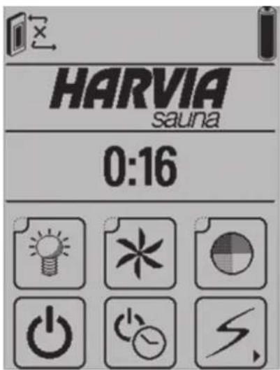
Function Icons

Light ON/OFF

Fan ON/OFF

Colour Light ON/OFF

Heater ON/OFF

Steamer ON/OFF

Sauna ON/OFF

Set the Pre-Setting Time

Main Menu

Function ON

Function OFF
Under the Sauna ON/OFF icon you'll find information on the conditions in your sauna, offering short cuts to change the settings affecting the current sauna bath.

Main Menu - Function Menus
(The displayed view varies according to the features acquired and enabled.)

Main Menu, page 1 Main MenuPagechange
Back to the Start Menu
Controls in Menus

Confirm

Exit/Cancel


Arrow icons
Track bar
QUICK GUIDE
FIRST SWITCH-ON
First time when you switch on the wireless control unit, it will automatically prompt you to calibrate the touch screen. The unit will guide you through the calibration process. After this you need to choose the desired panel language and set the day and time. Make the required settings and confirm. If the unit does not follow the above steps automatically, they can be carried out manually:
CALIBRATING THE TOUCH SCREEN (see section 2.10).
CHOOSING THE PANEL LANGUAGE
- Start Menu (the first menu to appear after switching on).
- Press the Main Menu icon. Use the page change to scroll through the Main Menu to User Settings and select.
- Use the page change to scroll to Panel Language and select.
- Choose a language and Confirm.
- Press the Exit icon to return to the Start Menu.
SETTING THE TIME AND DAY
- Press the Main Menu icon. Use the page change to scroll through the Main Menu to Miscellaneous and select.
- Use the page change to scroll to Adjust current time and select.
- Set day and confirm.
- Set time and confirm.
CHOOSING THE DEVICES TO BE ENABLED (see Service menu 2.9.9. b).
CONNECTIONS BETWEEN DEVICES
An icon in the upper left corner of the screen indicates whether the connections are active or whether there are lost connections or new devices to be connected. When connections are lost it can also be a case that the wireless control unit is outside the operating range (ca. 10 m) of the radio link.
Missing connections are established through device pair-up. See the following quick tips or chapter 2.9.4. 'Device Pair-Up' (further below).

Connection active – this icon is displayed while the devices are communicating with each other.

No connection – this icon is constantly displayed while the connections are disconnected.
DEVICE PAIR-UP
The following pair-up procedure is necessary to make the devices recognize each other and communicate:
- Switch on the wireless control unit. The Start Menu is displayed.
- Press the Main Menu icon. Use the page change to scroll through the Main Menu to Miscellaneous and select.
-
Use the page change to scroll to Device Pair-Up and select. This is the procedure to be used to establish a connection between devices/device pairs.
-
Under the selected menu item you will find the pair-up procedure menu. When you are establishing connections between device pairs for the first time, select Help. Read through the instructions and follow them.
-
Press the Confirm icon to switch back to the Pair-Up Procedure menu:


Pair-Up Help, page 1
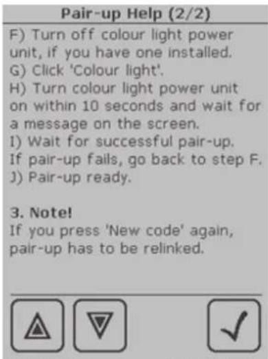
Pair-Up Help, page 2Pair-Up Procedure
A) Click 'New code', and the display will show 'Panel code changed. Renewing pairs is necessary.'
C) Click 'Heater', and the display will show 'Linking to Heater, switch power on now.'
D) Turn power unit on within 10 seconds, and the display will show 'Successful pair-up with heater.' If the pairing up was not successful, the display will show "Pair-up with heater FAILED". In this
case, return to Step B and repeat the procedure according to the instructions.
- To further add colour light, for example, press 'Colour light'.
NOTE! If you press the 'New Code' icon again, all connections are lost and must be re-established!

Pair-Up icon for heater power unit

Pair-Up icon for colour light power unit
HEATING UP THE SAUNA
- Start Menu (the first menu to appear after switching on).
- Use the function icons to switch functions on or off.
Light ON/OFF, Sauna ON/OFF, Heater ON/OFF, Steamer ON/OFF (model SACF165S)
While an icon is activated, the corresponding function is on.
The display shows up-to-date information on your sauna, including the temperature, humidity and remaining operating time.
- All displayed data can be changed. Go to settings by pressing the relevant reading or the icon up on the screen. Make the desired changes and confirm or cancel to return to the previous screen. Any confirmed changes only affect the current bath.
- When active icons are deactivated, the corresponding functions are switched off, and the display will show a recap of the most recent sauna bath, including the total time and energy consumption. Touch the screen to return to the Start Menu.
SETTING THE PRE-SETTING TIME - delayed heating

- Press the Set the Pre-Setting Time icon.
- Set the desired Delay after which the heater should start heating up the sauna. Use the arrow icons, which enable an accurate setting, or the track bar.
- Confirm by pressing the Sauna ON icon or cancel if you wish to make other settings. This takes you back to the Start Menu.
- While the function is activated, the display shows up-to-date information on your sauna, including the temperature, humidity and remaining time to heating. Activate from the current display Heater ON and/or Steamer ON, depending for which function you wish to
set the pre-setting time.


- To activate other functions, press the displayed function icons, for example Light ON.
1. HARVIA FENIX CONTROL UNIT
1.1. General
Harvia Fenix is a multidimensional control unit that makes it possible for you to enjoy your sauna in a wider variety of ways. The Fenix control unit allows you to totally control your sauna and the bathing conditions, such as the temperature, humidity and ventilation.
The control unit consists of a wireless control unit (touch screen), a power unit/power units and a sensor/sensors. The touch-screen control unit communicates with the power unit wirelessly or, alternatively, via a cable. See Figure 1.
The control unit can be used to control sauna heaters and Combi combined heaters/steamers within an output range of 2,3–15 kW. The Fenix wireless control unit operates to a distance of about 10 metres from the power unit, depending on structural obstacles.
1.2. Technical Data
Wireless control unit:
- Touch screen for controlling the sauna by selecting the desired functions and settings. Equipped with rechargeable batteries. The recharge stand must be placed in a dry place outside the sauna room. See Figure 2.
• Operating voltage 3,6 V. - Temperature adjustment range 40–110 °C.
• Humidity adjustment range 20–95 % RH.
- Operating time adjustment range: family saunas 0,5–6 h, no week timer public saunas in apartment buildings 0,5–12 h, required pause time min. 6 h.
For longer operating times consult the importer/manufacturer.
- Pre-setting time adjustment range 0–18 h.
- Programmable week timer.
- Lighting control, max. power 100 W, 230 V 1N\~
- Fan control, max. power 100 W, 230 V 1N\~
- Colour light control, max. power 2 x 50 W colour light unit 12 V DC.
Power units:
• Supply voltage 400 V 3N\~
• Max. load 15 kW/400 V 3N\~
- The power units are placed in a dry place outside the sauna room. They must not be embedded within the wall structure.
Sensors:
- The temperature sensor is equipped with a resettable overheat protector and a temperature-sensing NTC thermistor. The sensor is installed in the sauna room according to the instructions given in chapter 3.2.5. 'Installing the Temperature and Humidity Sensors'.
- The humidity sensor measures relative humidity. The sensor is installed in the sauna room according to the instructions given in chapter 3.2.5. 'Installing the Temperature and Humidity Sensors'.

flowchart
graph TD
    A["Wireless control unit SACF10"] -->|Radio link ca. 10 m| B["Radio antenna"]
    B --> C["Power unit SACF150 SACF165S"]
    C --> D["Heater (SACF150 SACF165S)"]
    D --> E["Steamer (SACF165S)"]
    F["Colour Light Power unit SACF100 (additional module)"] --> G["Colourlight"]
    H["Temperature sensor WX232"] --> C
    I["Humidity sensor WX325"] --> C
    J["Connection cable (optional)"] --> C
Figure 1. Interconnected devices of a Fenix control unit.
1.3. Configurations
The Harvia Fenix control unit consists of different devices which together allow comprehensive control over all aspects of sauna bathing. Available device packages are:
SACF10 wireless control unit for controlling power units, incl.
- Touch screen (wireless control unit)
- Recharge stand
● Wall-mounting plate for recharge stand - Charger
• 3 AA rechargeable batteries - Instructions for installation and use.
SACF150 power unit for controlling heater (max. 15 kW), incl.
● Power unit SACF150 for heater control
- Radio antenna and cable for communication with wireless control unit
• Temperature sensor
● Humidity sensor (available as an accessory)
SACF165S power unit for controlling combined heater/steamer (max. 16,5 kW), incl.
● Power unit SACF165S for heater/steamer control
● Radio antenna and cable for communication with wireless control unit
• Temperature sensor
- Humidity sensor
SACF100 power unit for controlling colour light, incl.
- Power unit SACF100 for controlling colour light units max. 2 x 50 W
- Cable for connection to power unit SACF150 or SACF165S
2. INSTRUCTIONS FOR USE
Before you switch the heater on check always that there aren't any things over the heater or in the near distance of the heater.
2.1. General
The wireless control unit is equipped with a user-prompting touch screen and is operated by three AA rechargeable batteries. The unit comes with a recharge stand. The recharge stand can be mounted into the wall or to the table but it must be placed outside the sauna room. Never take the wireless control unit to a heated sauna!
The wireless control unit is activated by pressing the black power switch above the screen. Activation brings the Start Menu with the function icons to the screen. Pressing a function icon switches the corresponding function on or off. Activated functions are indicated by a dark spot in the corner of relevant function icons and by 'active function' images above the screen.
The touch screen can be operated using a finger or, for example, the blunt end of a pencil. Avoid pressing the screen unnecessarily hard!
Clean the touch screen from time to time with a cloth or mild alcohol wipe.
2.1.1. Batteries
The instructions for fitting/changing the batteries can be found on page 59. The Fenix wireless control unit comes with NiMh AA HR6 rechargeable batteries, voltage 1,2 V. The rechargeable batteries can be replaced with non-rechargeable AA batteries. Note! Never place the wireless control unit in the recharge stand when fitted with non-rechargeable batteries do not use rechargeable and non-rechargeable batteries simultaneously together.
New, unused batteries must be charged uninterrupted for 24 hours before use. A complete recharge takes 12 hours. It is recommended to keep the wireless control unit in the supplied recharge stand when the unit is not in use – this way the batteries have charge when the unit is needed again.
Never use a damaged charger or battery. Remove the damaged battery from the unit. Dispose of the batteries according to the local regulations (concerning recycling etc.). Do not place batteries in household waste. Remove the batteries before disposing of the unit. Remove the unit from the charger before fitting/changing batteries.
2.2. Function Menus in the Main Menu and Function Icons
You can control all functions of your sauna using the function menus or the function icons.
Function Icons
Light, Fan and Colour Light are activated by pressing the relevant function icon on the screen.

Sauna ON/OFF
Press the Sauna ON/OFF icon to enable communication between the power unit and the wireless control unit. The wireless control
unit now displays information on the conditions in your sauna, such as temperature and humidity. Should the connection between the power unit and the wireless control unit be lost during the bath, the power unit will nevertheless be able to perform the programmed functions since all the settings remain stored in its memory.
Settings (operating time, temperature, humidity etc.) made in the Sauna ON mode only affect the current bath.
Settings made in the Sauna OFF mode are default settings which are stored in the memory of the wireless control unit.

The Set the Pre-Setting Time icon takes you directly to the screen where you can set the pre-setting time.

Pressing the Main Menu icon brings the function menus to the screen.
Through the Main Menu you can change all the settings related to your sauna. The function menus are explained in detail further below.
The pictures shown in this manual are meant as guidelines only since the screens may vary according to which features have been acquired and enabled for use.
Function icons can be added and removed from the screen. See 2.9.9. 'b) Installed / Enabled Features'.
2.3. Sauna Time Setup
Through the Sauna Time Setup menu you can make timer settings for your sauna.
• The operating time is the time the heater is on.
- The pre-setting time is the delay period after which the heater starts heating up the sauna. Do not forget to activate Heater ON and/or Steamer ON icon on the screen, depending for which function you wish to set the pre-setting time.
From the
Main Menu choose

2.4. Heater and Steamer Setup
2.4.1. Heater Setup
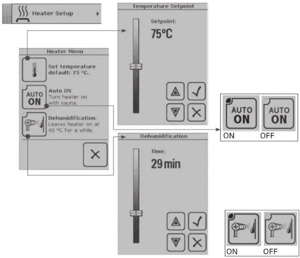
Under the Heater Setup menu you can set the temperature that the heater is expected to create in the sauna room.
While the AUTO ON icon is activated, the heater will switch on automatically when you press the Sauna ON/OFF icon. To switch on the heater with the AUTO ON icon deactivated, press the Sauna ON icon and then activate the Heater ON/OFF icon.
To keep your sauna in a good condition for longer, it is important that you have it dehumidified after bathing. With Fenix you can do this by leaving the heater on for a desired period at a temperature of 40 °C. Once the function is activated, it will stay on until the setting is changed by the user.
2.4.2. Steamer Setup
The steamer is controlled through the Steamer Setup menu. One of the two modes must be selected:
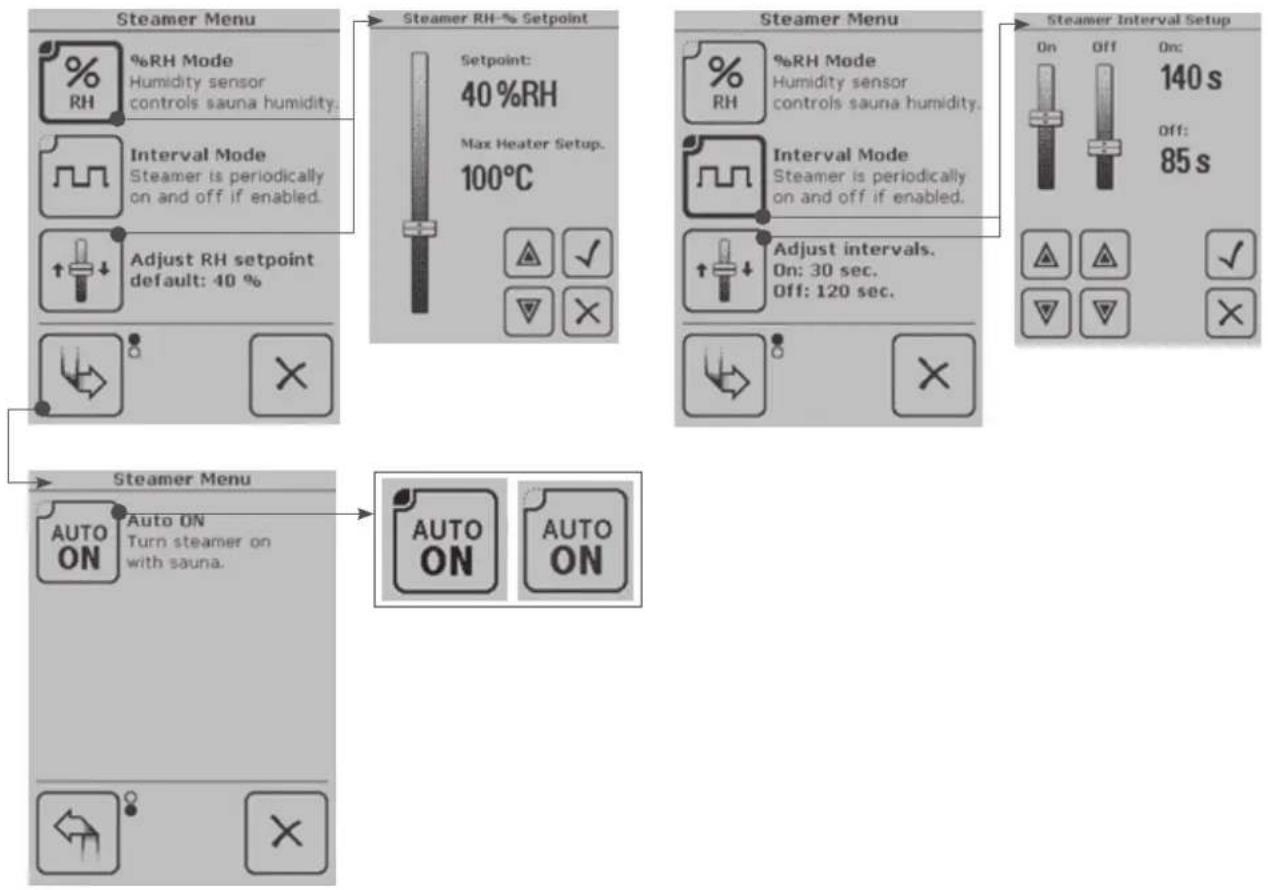
1) In the %RH Mode (%RH = relative humidity expressed as a percentage) the humidity sensor measures the humidity in the sauna room and the wireless control unit controls the steamer so that the humidity level is maintained as close to the set value as possible during the bath.
Set the desired humidity %RH. The sum of the steamer %RH setpoint and the max. heater setup cannot exceed 140.
2) The Interval Mode means that the steamer is on and off periodically. Set the desired duration of the two periods: for example the ON period at 140 seconds and the subsequent OFF period at 85 s. Confirm the settings.
While the AUTO ON icon is activated, the steamer will switch on automatically when you press the Sauna ON/OFF icon.
From the Main Menu choose
flowchart
graph TD
    A["Heater Setup"] --> B["Heater Menu"]
    B --> C["Set temperature default: 75 °C."]
    B --> D["Auto ON Turn heater on with sauna."]
    B --> E["Dehumidification Leaves heater on at 40 °C for a while."]
    F["Temperature Setpoint"] --> G["Setpoint: 75°C"]
    G --> H["Dehumidification Time: 29 min"]
    H --> I["ON OFF"]
From the Main Menu choose

flowchart
graph TD
    A["Steamer Menu"] --> B["%RH Mode Humidity sensor controls sauna humidity"]
    A --> C["Interval Mode Steamer is periodically on and off if enabled"]
    A --> D["Adjust RH setpoint default: 40%"]
    A --> E["Steamer RH-% Setpoint"]
    E --> F["Setpoint: 40%RH Max Heater Setup: 100°C"]
    F --> G["OK ✓ ✓ ✗ ✗"]
    H["Steamer Menu"] --> I["%RH Mode Humidity sensor controls sauna humidity"]
    H --> J["Interval Mode Steamer is periodically on and off if enabled"]
    H --> K["Adjust intervals. On: 30 sec. Off: 120 sec."]
    L["Steamer Interval Setup"] --> M["On Off On: 140 s off: 85 s"]
    L --> N["OK ✓ ✓ ✗ ✗"]
2.5. Colour Light and Light Setup
The colour light settings are available only if your Fenix control unit is equipped with the colour light feature. The feature can also be retrofitted.
2.5.1. Colour Light Setup
To activate the colour light in your sauna room, press the Colour Light function icon. If you wish to change the colour light settings, choose Colour Light Setup from the Main Menu.
Colour Light Menu:
There are four colours to choose from: blue, red, green, and yellow. You can choose just one colour or cycle all the four colours.
1) To cycle the colours, set the cycle speed determining how long each colour is on at slow, medium, or fast.
2) To use just one colour, press Change Colour to choose the desired colour. The colour that is left displayed will stay on.
The Set Brightness icon is used to adjust the brightness of the colour light.
While the AUTO ON icon is activated, the colour light will switch on automatically when your sauna is ready for bathing.
While the AUTO OFF icon is activated, the colour light will switch off automatically after the desired delay period, which can be set at max. 90 minutes.
Colour Light Unit Disabled indicates whether the colour light is in use or not.
From the
Main Menu choose
Colour Light Setup

flowchart
graph TD
    A["Colour Light Menu"] --> B["Change colour.<br>Colour: Blue"]
    A --> C["Set brightness."]
    A --> D["Cycle colours.<br>Click to set speed."]
    A --> E["Colour Light Unit disabled."]
    F["Colour Light Menu"] --> G["Auto ON<br>when sauna is ready."]
    F --> H["Auto OFF<br>after sauna goes off."]
    F --> I["Colour light unit disabled."]
    J["Colour Light Bus"] --> K["Adjust Colourlight Brightness<br>Brightness: 100%"]
    J --> L["Adjust Colourlight Turnover<br>Speed: Medium"]
    M["Colour Light Auto Off"] --> N["Delay: ---"]
    O["Colour Light Output"] --> P[" enableddisabled "]
2.5.2. Light Setup
To activate the lighting of your sauna, press the Light icon in the Start Menu. If you wish to change the light settings, choose Light Setup from the Main Menu.
From the Main Menu choose

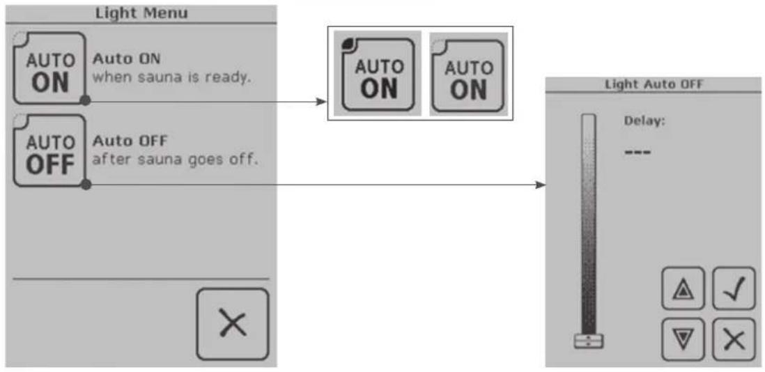
Light Menu:
While the AUTO ON icon is activated, the lights will switch on automatically when your sauna is ready for bathing.
While the AUTO OFF icon is activated, the lights will switch off automatically after the desired delay period, which can be set at max. 90 minutes.
flowchart
graph LR
    A["Light Menu"] --> B["Auto ON when sauna is ready."]
    A --> C["Auto OFF after sauna goes off."]
    B --> D["Auto ON"]
    C --> E["Auto OFF"]
    D --> F["Light Auto OFF"]
    E --> F
    style A fill:#f9f,stroke:#333
    style F fill:#ccf,stroke:#333
2.6. Fan Setup
To activate the fan of your sauna, press the Fan icon in the Start Menu. If you wish to change the fan settings, choose Fan Setup from the Main Menu.
Ventilation Menu:
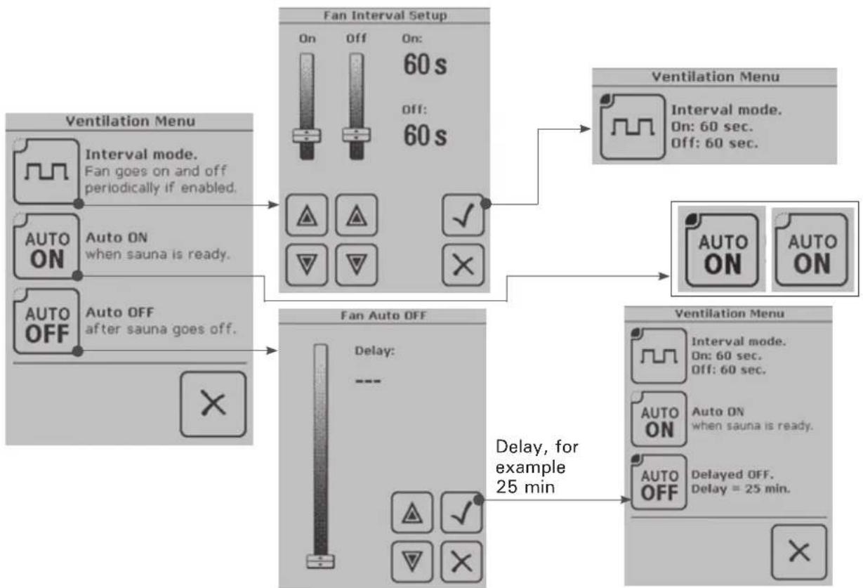
The fan can be set to switch on or off automatically.
While the AUTO ON icon is activated, the fan will switch on automatically when your sauna is ready for bathing.
While the AUTO OFF icon is activated, the fan will switch off automatically after the desired delay period, which can be set at max. 90 minutes.
If you activate the Interval Mode, the fan will be on and off periodically. Make the necessary ON and OFF settings: for example, set the fan to blow air into the sauna room for a period of 60 seconds (ON) and to switch OFF for the subsequent 60 s.
From the Main Menu choose

flowchart
graph TD
    A["Ventilation Menu"] --> B["Fan Interval Setup"]
    B --> C["Ventilation Menu"]
    subgraph "Fan Interval Setup"
        D["On: 60 s Off: 60 s"]
        E["Auto ON when sauna is ready."]
        F["Auto OFF after sauna goes off."]
    end

    subgraph "Fan Auto Setup"
        G["On: Off: 60 s Off: 60 s"]
        H["Auto ON when sauna is ready."]
        I["Auto OFF after sauna goes off."]
    end

    subgraph "Ventilation Menu"
        J["On: 60 sec Off: 60 sec"]
        K["Auto ON when sauna is ready."]
        L["Auto OFF Delayed OFF: 25 min"]
    end

    D --> H
    E --> I
    F --> J
    G --> K
    H --> L
    I --> M["Delay, for example 25 min"]
    J --> N["Delay, for example 25 min"]
2.7. Week Timer
Electrical safety regulations allow the week timer feature to be used only in community saunas!
The week timer settings allow you to program a weekly schedule, which is especially handy if you use your sauna regularly every week. Set the desired bathing time for any chosen day – or even every day – of the week.
When the weekly schedule starts, the wireless control unit will be activated even if switched off.
A pause of at least 6 h is required between each two periods created for the Week Timer schedule.
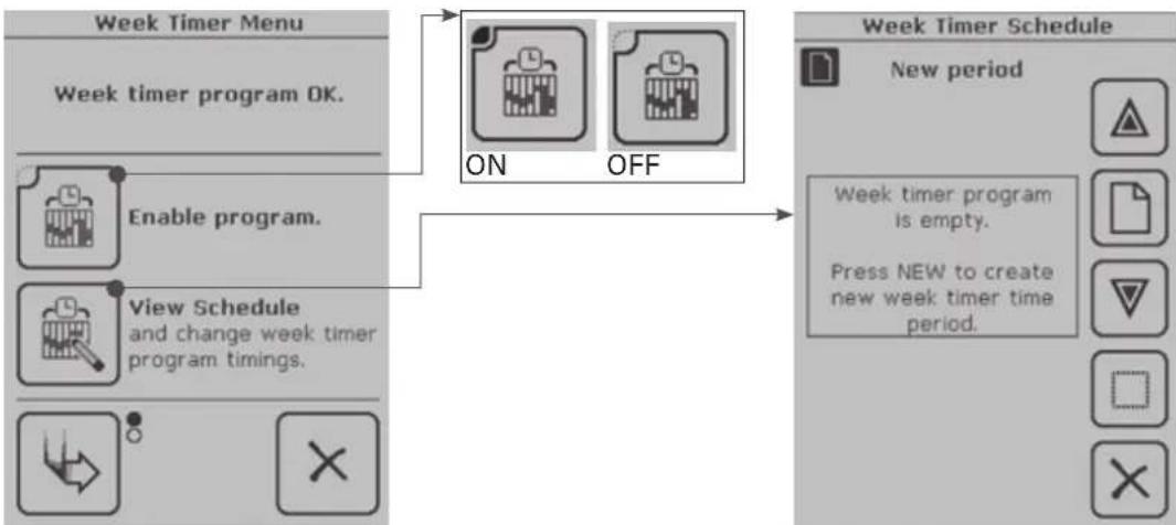
Week Timer Menu:
Choose Enable Program to activate all created programs to be run at set times.
View Schedule brings to the screen a recap of your weekly schedule if you have created one; if you do not have one, the display shows 'Week timer program is empty'. You can also change the schedule in this menu.
Create New Program Timing
- Set the program start time, which is the time you wish to start bathing. Confirm or, if you wish to return to the previous screen, cancel.
- Set the program ending time and confirm or cancel.
- Set the day(s). You can set more than one day at the same time.
- Confirm the settings or press Cancel to return to the previous screen.
- Set the desired temperature for the programmed period.
- Set the desired humidity level for the programmed period. Make sure you have the Enable Steamer box ticked.
- Confirm the settings or press Cancel to return to the previous screen.
The display now shows a recap of the settings made. Confirm or press Cancel to return to the previous screen.
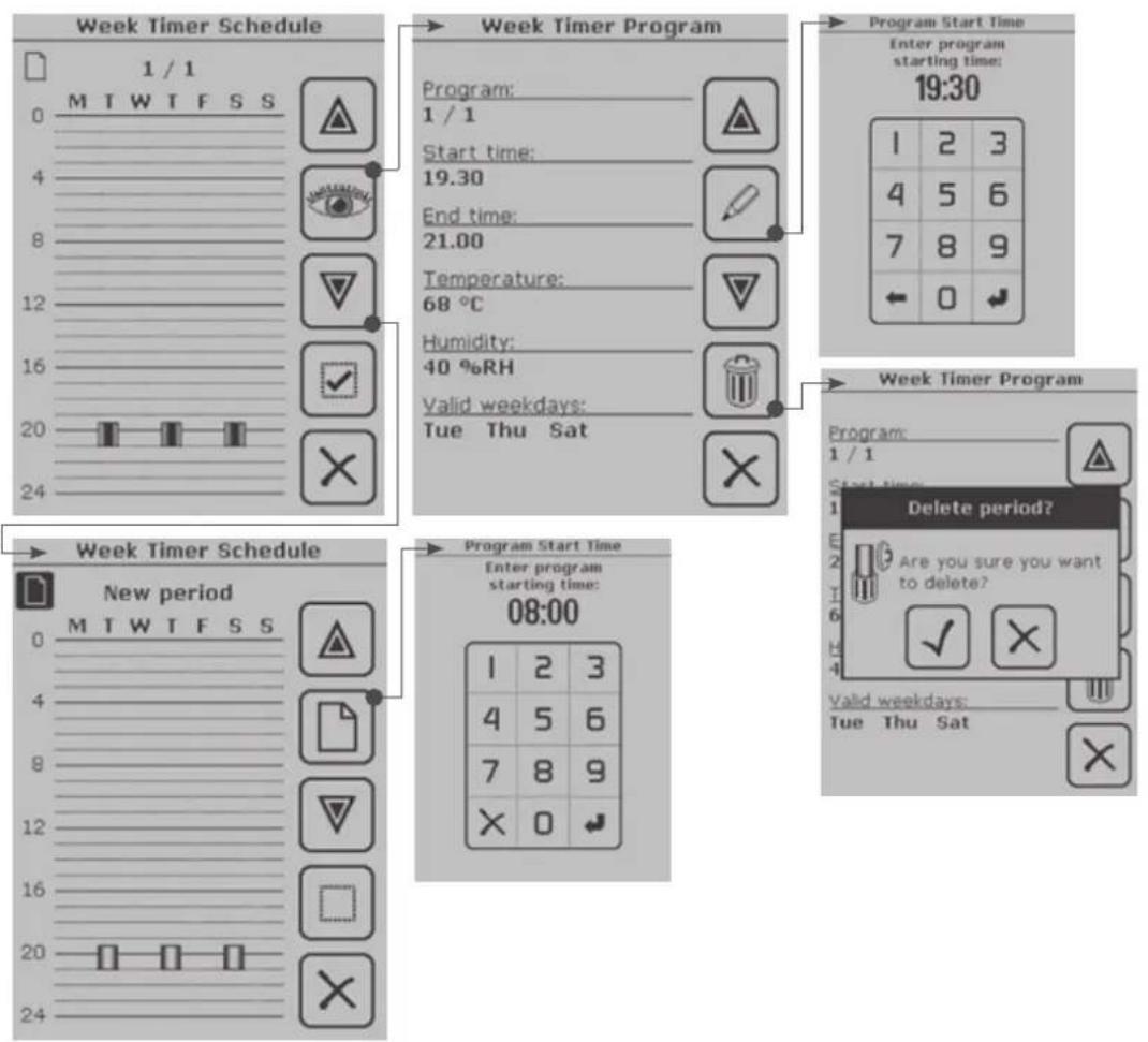
If you choose View Schedule again after programming, the displayed week timer schedule will contain the period you just programmed. Here you can change the schedule or, for example, remove a schedule without deleting it permanently, meaning that it will remain stored in the memory for later activation. You can also add/create new schedules. See the following pages for examples.
Delete All Periods deletes all the periods created for a week timer schedule. If you choose this option, the display will show a message asking you to confirm that you wish to delete all periods. Confirm or cancel as required.
Check Validation checks the status of the Week Timer schedule and displays any possible problems on the screen.
- Heating periods: checks the heating period length to make sure the max. operating time is not exceeded.
- Resting periods: checks that the pauses in the Week Timer schedule are at least 6 h.
- Periods enabled: displays the activated periods of the weekly schedule.
• Master enable: on / off. - Check progress: indicates the stage of the check.
From the
Main Menu choose

flowchart
graph TD
    A["Week Timer Menu"] --> B["Enable program."]
    B --> C["View Schedule and change week timer program timings."]
    C --> D["ON OFF"]
    D --> E["Week Timer Schedule"]
    E --> F["New period"]
    F --> G["Week timer program is empty."]
    F --> H["Press NEW to create new week timer time period."]

Press the Page Change icon to move to the next page.

flowchart
graph TD
    A["Week Timer Menu"] --> B["Create new program timing."]
    A --> C["Erase all program timings! This cannot be undone."]
    A --> D["Check validation"]
    B --> E["Delete ALL? Are you sure you want to delete ALL program periods? This can't be undone."]
    E --> F["Validating Week Timer"]
    F --> G["Heating periods (2 / 2) Resting periods Errors: 3 Periods enabled (2 / 2) Master enable On Check progress"]
    G --> H["Attention! Required 6 h resting time between programs does not come true. Number indicates the amount of errors in the week program."]
    I["Program Start Time"] --> J["Enter program starting time: 19:30"]
    K["Program End Time"] --> L["Enter program ending time: 21:00"]
    M["Program Weekdays"] --> N["Choose weekdays when active: Monday Tuesday Wednesday Thursday Friday Saturday Sunday"]
    O["Program Temperature"] --> P["Set temperature: 68°C"]
    Q["Program Humidity"] --> R["Set humidity: 40%RH Enable steamer"]
    S["Steamer enabled"] --> T["Program Humidity: Set humidity: 40%RH Enable steamer"]
    U["Confirm changes?"] --> V["Press OK to accept these values. Start time: 19.30 End time: 21.00 Temperature: 68°C Humidity: Steamer disabled. Valid weekdays: Tue Thu Sat"]
    W["Exit/Cancel"] --> X["Change"] --> Y["Confirm/Next"] --> Z["Mon, Tue, Wed, Thu, Fri"] --> AA["Sat, Sun"]
To change or delete a created Week Timer period one at a time, choose View Schedule.
flowchart
graph TD
    A["Week Timer Schedule"] --> B["1 / 1"]
    B --> C["MTWTFSS"]
    C --> D["Start Time: 19.30"]
    D --> E["End Time: 21.00"]
    E --> F["Temperature: 68 °C"]
    F --> G["Humidity: 40 %RH"]
    G --> H["Valid weekdays: Tue Thu Sat"]
    H --> I["Program Start Time"]
    I --> J["Enter program starting time: 19:30"]
    J --> K["1 2 3"]
    K --> L["4 5 6"]
    L --> M["7 8 9"]
    M --> N["← 0 ↓"]
    N --> O["Week Timer Program"]
    O --> P["1 / 1"]
    P --> Q["Start Time: 19:30"]
    Q --> R["Delete period?"]
    R --> S["Are you sure you want to delete?"]
    S --> T["Valid weekdays: Tue Thu Sat"]
    T --> U["Program Start Time"]
    U --> V["Enter program starting time: 08:00"]
    V --> W["1 2 3"]
    W --> X["4 5 6"]
    X --> Y["7 8 9"]
    Y --> Z["× 0 ↓"]

Scroll through periods

Recap of the period(s)

Scroll through periods

Activate period

Return/Cancel

New period

Make changes

Delete period
2.8. User Settings
Through the User Settings menu you can control settings related to the use of the wireless control unit.
User Settings Menu:
Backlight Mode
Alternative modes:
□ Backlight on while unit is on
□ Backlight on during baths
□ 2 min switch off delay
□ 30 s switch off delay
□ 10 s switch off delay
□ Always off
Display Contrast
Increase or decrease the contrast and brightness of the screen as necessary.
Options
You can adapt the information on the display as follows:
1) You can replace the digital clock, displayed in the Start Menu by default, with an analogue clock.
2) You can choose the display to cycle any selected/activated data, such as energy consumption and/or heater output, during sauna baths. The informative screen contains, during sauna baths, a recap of the selected aspects, such as energy consumption and/or heater output.
Panel Language
Choose the language to be used by the wireless control unit.
Key Beep Tone
The tone range varies from silent to loud beep.
Audible Notifications
You can choose to hear a notification sound when your sauna is ready for bathing and/or when a week timer event becomes active.
2.9. Miscellaneous
2.9.1. Statistics
Pressing the Statistics icon brings to the screen a recap of the most recent sauna bath (total time and energy consumption). Before the first bath there is no data stored in the memory. Touch the screen to return to the previous screen.
2.9.2. Curve Diagram
The current readings of the temperature and humidity sensors or the readings taken during the most recent sauna bath are displayed as a graph.
2.9.3. Adjust Current Time and Day
Set the correct time and day. The clock must be adjusted for summer/winter time.
2.9.4. Device Pair-Up
This procedure is used to establish a connection between new devices/device pairs and to re-establish any lost connections. The icon in the upper left corner of the Start Menu indicates whether the connections are active or whether connections are missing.

Connection active

No
connection
Note! The pair-up procedure is unnecessary if the wireless control unit is connected to the power unit with a cable. In this case the wireless control unit does not need batteries or charging, since the required operating voltage is supplied from the power unit through the cable.
Device pair-up
The following pair-up procedure is necessary to make the devices recognize each other and communicate:
- Switch on the wireless control unit. The Start Menu is displayed.
- Press the Main Menu icon. Use the page change to scroll through the Main Menu to Miscellaneous and select.
-
Use the page change to scroll to Device Pair-Up and select. This is the procedure to be used to establish a connection between devices/device pairs.
-
Under the selected menu item you will find the pair-up procedure menu. When you are establishing connections between device pairs for the first time, select Help. Read through the instructions and follow them.
-
Press the Confirm icon to switch back to the Pair-Up Procedure menu:


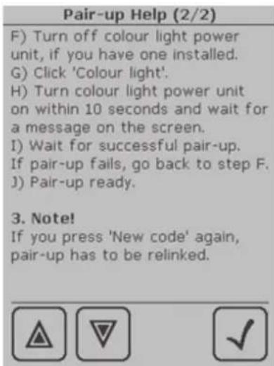
Pair-Up Procedure Pair-Up Help, page 1 Pair-Up Help, page 2
A) Click 'New code', and the display will show 'Panel code changed. Renewing pairs is necessary.'
C) Click 'Heater', and the display will show 'Linking to Heater, switch power on now.'
D) Turn power unit on within 10 seconds, and the display will show 'Successful pair-up with heater.' If the pairing up was not successful, the display will show "Pair-up with heater FAILED". In this
case, return to Step B and repeat the procedure according to the instructions.
- To further add colour light, for example, press 'Colour light'.
NOTE! If you press the 'New Code' icon again, all connections are lost and must be re-established!

Pair-Up icon for heater power unit

Pair-Up icon for colour light power unit
2.9.5. Panel Power Settings
Set the desired standby delay period after which the power to the wireless control unit is switched off.
2.9.6. Additional Options and Settings
Here you can activate a safety option which automatically switches off the power to the unit devices if the connections between them are lost. The factory setting of this feature is 'deactivated'.
2.9.7. Detailed Version Info
Here you can find information on the software, wireless control unit, power unit and, if installed, colour light unit included in the configuration. This information is needed when you update the software.
2.9.8. Sensor Reading Adjustment
Here you can change the readings of the temperature sensors (NTC thermistor) and the humidity sensor from the measured ones. The reading can be corrected by +/- 10 units. This adjustment is to ensure that the desired temperature is achieved in the sauna room. To find out the required correction, measure the temperature and, if necessary, humidity of the sauna room using external meters.
Temperature sensor A = the NTC thermistor is in the same box as the overheat protector.
Temperature sensor B = the NTC thermistor is in the same box as the humidity sensor.
Humidity sensor = the sensor measuring the humidity level in the sauna room.
NOTE! Correcting sensor readings do not affect the operation of the overheat protector. The overheat protector cuts off the power if the temperature around it exceeds 150°C. See chapter 3.2.6. 'Resetting the Overheat Protector'.
2.9.9. Service Menu
To enter the Service Menu select Miscellaneous in the Main Menu. Use the arrow icon to scroll through to Service Menu. To access the Service Menu, you must enter service code 6143. The code is fixed and cannot be changed.
a) Auxiliary Relay Function
Power units SACF150 and SACF165S have a 230 V 1N\~ auxiliary output which can be used for different functions.
Auxiliary Output Setup:
Ventilation Fan: Use the AUX output for controlling the fan (max. 100 W) of your sauna.
Heating control: Use the AUX output for controlling the electric heating of the building. The output gives 230 V 1N\~ in Sauna ON mode.
Indicator: Use the AUX output for installing an indicator light (max. 100 W) that tells you when your sauna is ready for bathing.
b) Installed/Enabled Features
Here you can choose the devices acquired and enabled. When enabled, they will be displayed as

flowchart
graph TD
    A["Service Menu"] --> B["Service Menu"]
    B --> C["Auxiliary Output Setup"]
    C --> D["Select AUX Output Function:"]
    D --> E["Ventilation Fan"]
    D --> F["Heating Control"]
    D --> G["Indicator"]
    C --> H["Available Features"]
    H --> I["Select features to be available:"]
    I --> J["Steamer"]
    I --> K["Light"]
    I --> L["Colour Light"]
    I --> M["Radio Link"]
function icons on the touch screen of the wireless control unit. This way you can also adapt the amount of data displayed. The features available for selection are steamer, light, colour light and radio link.
For wireless communication you must have at least the radio link feature selected, since it enables the real-time communication between devices.
c) Heater Watts Setup
Here you can enter the output of your heater for the kWh meter. If you cannot find a suitable option from the list, enter the output in watts.
d) Steamer Watts Setup
Here you can enter the output of your steamer for the kWh meter. If you cannot find a suitable option from the list, enter the output in watts.
e) Max On Time Setup
● Family sauna 4 h, max. 6 h:
Select the max. operating time for the heater. The week timer feature is not available in family saunas.
- Public sauna in an apartment building 4 h, 6 h, max. 12 h, pause time 6 h:
Select the max. operating time for the heater, the week timer feature is in use. When creating a weekly schedule, bear in mind that the operating time must be followed by a 6-hour pause.
- For longer operating times consult the importer/manufacturer.
f) Load Factory Settings
You can restore the wireless control unit to its factory settings, which means that all the settings you have made are returned to the defaults.
During restore there must be connection to the power unit.
- From the Main Menu select Miscellaneous.
- Use the page change to scroll to Service Menu and select. Enter the service code 6143 and confirm.
- Use the page change to scroll through the menu to Load Factory Settings and select.
- You are now asked to confirm that you wish to erase all the settings you have made, returning to the default settings chosen by the manufacturer. Confirm to restore the factory settings.
2.10. Options
When you press the power switch lightly in the Sauna OFF mode, the Options menu appears on the screen. This menu is a short cut to the following functions:
Standby mode, for switching the screen to standby mode and switching off the power.
Sauna on, for switching on the sauna.
Sauna on with delay, for setting the pre-setting time after which the sauna starts heating up.
Next, takes you the next menu page.
Calibration, see chapter 2.10.1.
Exit menu, takes you back to the Start Menu.
2.10.1. Calibrating the Touch Screen
Calibrate the screen if it stops responding or responds slowly. When you press the power switch in the Sauna OFF mode, the Options menu appears on the screen. To switch from one menu item to another, press the power switch repeatedly. To perform the calibration, first switch to Next page. Select a section by pressing the power switch for a longer time. Select
Recalibrate and perform the calibration according to the displayed instructions on the screen.

3. INSTRUCTIONS FOR INSTALLATION
The electrical connections of the control unit may only be made by an authorised, professional electrician and in accordance with the current regulations. When the installation of the control unit is complete, the person in charge of the installation shall pass on to the user the instructions for installation and use that come with the unit and shall give the user the necessary training to use the heater and the control unit!
For an overall view of the Harvia Fenix control unit see Figure 1.
3.1. Installing the Wireless Control Unit
The Fenix wireless control unit comes with a table recharge stand that can be attached to a table with a screw. The recharge stand can also be wall mounted using a separate wall-mounting plate. When installing the recharge stand, observe the distance to the nearest socket: the cord measures approximately 1,5 m in length. The wall-mounting plate is fixed to the wall with three screws, and the recharge stand is fastened to the plate with two screws. The recharge stand is installed outside the sauna room, in a dry place with an ambient temperature of >0 °C. The wireless control unit can, if necessary, be attached to the charger with a screw. See Figure 2.
Check the operating range of the radio link (up to 10 m from the power unit) when installing the recharge stand. The range varies according to the structural obstacles.
The wireless control unit can, alternatively, be connected to the power unit with a cable. The required operating voltage is then supplied from the power unit through the cable and batteries can not be used. If connected to the power unit with a cable, the wireless control unit can be fixed to a wall using a special rear cover designed for wall mounting (see Figure 3). In this case you do not need a recharge stand.
When you first switch on the wireless control unit, it will automatically prompt you to calibrate the touch screen. The screen will guide you through the calibration process. After this you are asked to choose the desired panel language and set the day and time. Make the required settings and confirm. If the unit does not follow the above steps automatically, they can be carried out manually (see Quick Guide).
Before the wireless control unit is taken into use, the installer shall enable the installed features through the Service Menu.
To add or remove function icons on the screen:
- Go to the Main Menu.

-
Use the page change to scroll through to Miscellaneous and select.
-
Scroll to Service Menu and enter the service code 6143.
Confirm by pressing Confirm/Next.

-
Choose Installed/Enabled Features. Here you can activate the required features, which are then displayed as function icons on the touch screen of the wireless control unit.
-
Confirm the settings.

- Select the desired
function for the auxiliary output and Confirm. 74

Figure 2. Wall mounting of the recharge stand.


natural_image
Two technical diagrams showing a grid fence with a shaded rectangular component and a gray rectangular device, both without any text or symbols.Figure 5. Wall mounting of the power unit.
3.2. Installing the Power Unit
The power unit of the Harvia Fenix control unit and the power unit for colour light, if installed, are placed outside the sauna room, in a dry place with an ambient temperature of >0 ^ . The power units can be fixed to a wall. See Figure 4 for instructions on how to open the power unit cover and how to fix the unit to the wall.
Note! The power units must not be embedded into the wall, since this may cause excessive heating of the internal components of the unit and lead to damage. See Figure 5.
3.2.1. Electrical Connections of Power Unit SACF150 for Heater
Power unit SACF150 is designed for controlling electric heaters with an output of max. 15 kW.
This power unit can also be used for controlling the lighting (max. 100 W) in the sauna room and, through the auxiliary output (max. 100 W), the 'sauna ready' indicator light, ventilation fan or electric heating of the building. For instructions on
Table 1.
| Heater output kW | Fuse (A) | Supply cable | Connection cable 400V 3N~ |
| 0-6 kW 3 x 10 | 5 x 1,5 | 5 x 1,5 | |
| <6-11 kW 3 x | 16 5 x 2,5 | 5 x 1,5 | |
| <11-15 kW 3 | x 25 | 5 x 6,0 | 5 x 2,5 |
Table 2.
| Heater model | Output (kW) | Fuse (A) | Supply cable | Connection cable 400V 3N~ |
| KV50SE 5 | ,0 3 x 1 | 0 5 x 1,5 | 7 x 1,5 | |
| KV60SE 6 | ,0 3 x 1 | 0 5 x 1,5 | 7 x 1,5 | |
| KV80SE 8 | ,0 3 x 1 | 6 5 x 2,5 | 7 x 2,5 | |
| KV90SE 9 | ,0 3 x 1 | 6 5 x 2,5 | 7 x 2,5 | |
| T7C 7,0 3 | x 16 5 | x 2,5 7 x | 2,5 | |
| T9C 9,0 3 | x 16 5 | x 2,5 7 x | 2,5 | |
| K11GS 10 | ,3 3 x 1 | 6 5 x 2,5 | 5 x 1,5 | +4 x 1,5* |
| K13,5GS | 13,5 3 x | 20 5 x 6 | ,0 5 x 2,5 | +4 x 1,5* |
| K15GS 15 | ,5 3 x 2 | 5 5 x 6,0 | 5 x 2,5 | +4 x 1,5* |
*) For further instructions see the instructions for installation and use for Club Combi
how to select the desired AUX output function see chapter 2.9.9. a).
The temperature sensor in the sauna room must be connected to the SACF150 power unit. You can also install a humidity sensor, available as an accessory, for measuring the humidity level in the sauna. For instructions on how to install the sensors see chapter 3.2.5.
The electrical connections of the power unit are made according to Figure 6. For wireless communication, the power unit must be paired up with the wireless control unit after installation (see chapter 2.9.4).
Table 1 shows the cable thickness and fuse size, depending on the heater output, to be used with the Fenix SACF150 power unit. For more detailed installation instructions see the instructions for installation and use for the selected heater model.
3.2.2. Electrical Connections of Power Unit SACF165S for Steamer/Heater
Power unit SACF165S is designed for controlling heaters of max. 15 kW, steamers of max. 5 kW, and Combi combined heaters/steamers of max. 16,5 kW.
This power unit can also be used for controlling the lighting (max. 100 W) in the sauna room and, through the AUX output (max. 100 W), the 'sauna ready' indicator light, ventilation fan or electric heating of the building. For instructions on how to select the desired AUX output function see chapter 2.9.9. a).
The temperature and humidity sensors in the sauna room must be connected to the SACF165S power unit. For instructions on how to install the sensors see chapter 3.2.5.
The electrical connections of the power unit are made according to Figure 7–9, depending on the heater model. For wireless communication, the power unit must be paired up with the wireless control unit after installation (see chapter 2.9.4).
Table 2 shows the cable thickness and fuse size, depending on the heater model, to be used with the Fenix SACF165S power unit. For more detailed installation instructions see the instructions for installation and use for the selected heater/steamer model.
3.2.3. Electrical Installations of Power Unit SACF100 for Colour Light
Power unit SACF100 is designed to be used for controlling two Harvia Colour Lights with bulbs of max. 50 W / 12 V DC. The electrical connections are made according to Figure 10.
The colour light unit is connected to power unit SACF150 or SACF165S via the included cable measuring approximately 1,5 m in length. The Harvia Colour Light also comes with a cable (T 180 °C) for connection to power unit SACF100.
The SACF100 unit is supplied with power (230 V 1N\~) via an installation cable of 3 x 1,5 mm ^2 .
To be able to use the power unit SACF100 for colour light, the colour light feature of the wireless control unit must be activated (see Chapter 2.5.1.), and for wireless communication, the colour light unit must be paired up with the wireless control unit (see Chapter 2.9.4).

flowchart
graph TD
    A["Cable or Radio connection to SACF10"] --> B["Option 1: Radio antenna"]
    A --> C["Option 2: Cable"]
    D["Sensors"] --> E["Must be installed"]
    D --> F["Must be installed"]
    D --> G["Humidity sensor"]
    H["Option for SACF100 Colour light unit"] --> I["Optional"]
    J["Voltage selection switch"] --> K["220, 230, 240 V 1N- Operation"]
    J --> L["110, 115, 120 V 1N- Operation"]
    M["Configuration AUX out"] --> N["Option 1"]
    M --> O["Option 2"]
    M --> P["Option 3"]
    Q["Sensors"] --> R["Blue White Red Yellow Blue Brown"]
    S["Internal Cabling DO NOT TOUCH!"] --> T["Power unit SACF150 is designed to be used with wireless unit SACF10. The units can be connected via radio link or connection cable. When connected with a cable, SACF150 supplies operating voltage to SACF10. A temperature sensor is needed to operate SACF150; a humidity sensor can be used but is not required. Relay operated AUX output is 230 V 1N~ max 100 W. The use of this output is configured in SACF10 settings. The options are: - indicator light for indicating when the sauna is ready - Heating control for switching off main heating while bathing - Sauna room fan"]
    U["Fuse of light and AUX"] --> V["In 230 V 1N- mode 1.25 Ah In 115 V 1N- mode 2.5 Ah"]
    W["Fuse of electronic card"] --> X["In 230 V 1N- mode 63 mA In 115 V 1N- mode 125 mA"]
    Y["Heater unit Max. 15 kW 400 V 3N~"] --> Z["L1 L2 L3 N ⊕ U V W N ⊕ Input"]
Figure 6. Electrical connections of power unit SACF150 for heater

flowchart
graph TD
    A["Cable or Radio connection to SACF10"] --> B["Option 1: Radio antenna"]
    A --> C["Option 2: Cable"]
    D["Sensors"] --> E["Must be installed"]
    D --> F["Must be installed"]
    D --> G["Humidity sensor"]
    H["Option for SACF100 Colour light unit"] --> I["Optional"]
    J["Voltage selection switch"] --> K["Blue: White, Red, Yellow, Blue, Brown"]
    L["Configuration AUX out"] --> M["Option 1"]
    L --> N["Option 2"]
    L --> O["Option 3"]
    P["Internal Cabling DO NOT TOUCH!"] --> Q["L1 L2 L3 N U V W N W1 P"]
    R["Fuse of light and AUX"] --> S["In 230 V 1N- mode 1.25 Ah, In 118 V 1N- mode 2.5 Ah"]
    T["Fuse of electronic card"] --> U["In 230 V 1N- mode 63 mA, In 115 V 1N- mode 125 mA"]
    V["SACF165S installation instructions"] --> W["Power unit SACF165S is designed to be used with wireless control unit SACF10. The units can be connected via radio link or connection cable. When connected with a cable, SACF165S supplies operating voltage to SACF10. Temperature and humidity sensors are needed to operate SACF165S. Relay operated AUX output is 230 V 1N-, max 100 W. The use of this output is configured in SACF10 settings. The options are: Indicator light for indicating when the sauna is ready, Heating control for switching off main heating while bathing, Sauna room fan"]
    X["Voltage selection switch"] --> Y["Operation: 220, 230, 240 V 1N- Operation: PEZ"]
    X --> Z["Operation: 110, 115, 120 V 1N- Operation: BLI"]
    AA["Sensors"] --> AB["Blue: White, Red, Yellow, Blue, Brown"]
    AC["Sensors"] --> AD["Reserved: Internal cabling, N, AUX Out, Light out, Internal cabling, Internal cabling"]
    AE["Voltage selection switch"] --> AF["Input: Max. 15.5 kW 400 V 3N~ KV50SE-KV90SE KV50SEA-KV90SEA T7C-T9C T7CA-T9CA"]
Figure 7. Electrical connections of power unit SACF165S for steamer/heater (Combi heaters)
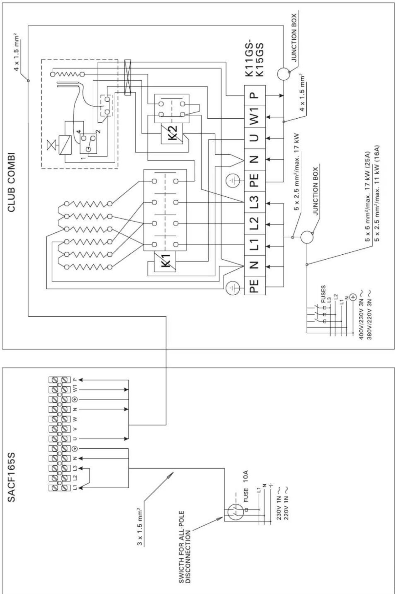
Figure 8.
EN
Power unit SACF165S
Heater and steamer SS20/SS20A
Internal Cabling DO NOT TOUCH!

flowchart
graph TD
    A["Input"] --> B["L1 L2 L3 N"]
    B --> C["Heater unit Max. 15 kW 400 V 3N~"]
    C --> D["Steamer SS20 SS20A (automatic)"]
    D --> E["L N P"]
    style A fill:#f9f,stroke:#333
    style C fill:#ccf,stroke:#333
    style D fill:#cfc,stroke:#333
Figure 9. Electrical connections of power unit SACF165S (heater and SS20/SS20A steamer)

Figure 10. Electrical connections of power unit SACF100 for colour light
3.2.4. Installing the Radio Antenna
For wireless communication, the radio antenna must be connected to the SACF150 or SACF165S power unit. The antenna is attached near to the power unit (see Figure 11) using two-sided tape.
3.2.5. Installing the Temperature and Humidity Sensors
Wall-mounted heaters and Combi heaters (see Figure 12).
The temperature sensor is wall-mounted above the heater, along the vertical centre line running parallel to the sides of the heater, at a distance of 100 mm from the ceiling.
Floor-mounted heaters and Combi heaters (see Figure 13).
Alternative 1:
The temperature sensor is wall-mounted above the heater, along the vertical centre line running parallel to the sides of the heater, at a distance of 100 mm from the ceiling.
Alternative 2:
The temperature sensor is mounted to the ceiling above the heater, at a distance of 200 mm from the vertical centre line of the heater's side.
For installing the temperature sensor near vents see the instructions in Figure 14.
With a separate steamer (SS20/A), observe that the temperature sensor must not be installed in the area affected by steam (see Figure 13).
The humidity sensor is wall-mounted as far from the heater as possible and at a distance of 500–700 mm from the ceiling.

natural_image
Technical line drawing of an electronic device chassis with connectors, modules, and wiring (no text or symbols)Figure 11. Installing the radio antenna of the Fenix control unit
3.2.6. Resetting the Overheat Protector
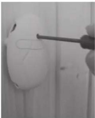
The components in the sensor box control the operation of the control unit. The sensor box contains a temperature sensor and an overheat protector. An NTC thermistor senses the temperature, and the resettable overheat protector cuts off the heater power in the case of malfunction, after which the protector can be easily reset. The reset button of the overheat protector is shown in Figure 15.
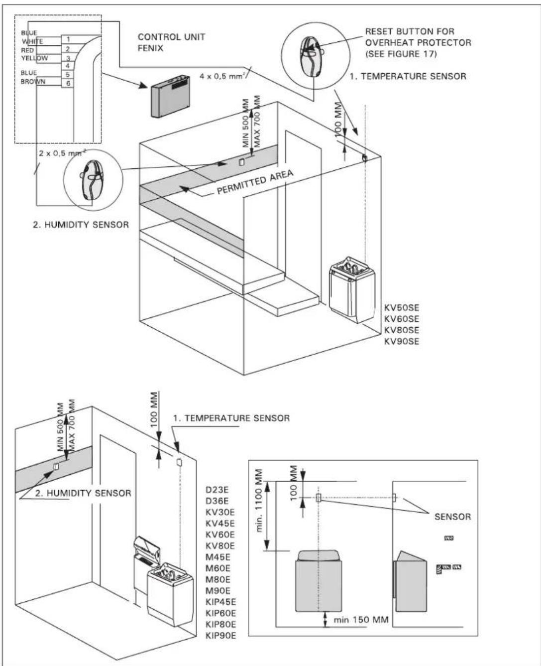
Figure 12. Installing the temperature and humidity sensors of the Fenix control unit, wall-mounted heaters

| TYPE | Aminmm | Amaxmm | Dminmm |
| T7C | 100 | 130 | 1250 |
| T9C | 120 | 150 | 1250 |
| T9 | 120 | 150 | 1250 |
| T10,5 | 150 | 180 | 1250 |
| K9 | 120 | 220 | 1400 |
| K10,5 | 120 | 220 | 1400 |
| F10,5 | 100 | 200 | 1400 |
| K11GS | 70 | 170 | 1200 |
| K13.5GS | 100 | 200 | 1400 |
| K15GS | 100 | 200 | 1400 |
Figure 13. Installing the temperature and humidity sensors of the Fenix control unit, floor-mounted heaters

Figure 14. Installing the temperature sensor near to a vent
natural_image
Close-up of a hand using a screwdriver to apply white plastic or plastic adhesive on a wall (no text or symbols visible)Figure 15. Reset button of the overheat protector
STEUEREINHEIT FENIX
natural_image
Technical illustration of an electronic device with a switch and internal components, shown in isometric view (no text or symbols)natural_image
Two technical diagrams showing a grid fence with a shaded rectangular component and a separate 3D block (no text or symbols)natural_image
Technical line drawing of an electronic device chassis with labeled components and wiring (no text or symbols present)natural_image
Close-up of a hand holding a screwdriver touching a white circular object (no text or symbols visible)natural_image
Two technical diagrams showing a grid fence with a shaded rectangular component and a separate rectangular device (no text or symbols present)natural_image
Technical line drawing of an electronic device chassis with labeled components and wiring (no text or symbols present)natural_image
Close-up of a hand using a screwdriver to apply plastic wrap onto a white plastic object (no text or symbols visible)
- HARVIA FENIX CONTROL UNIT ...... 62
- INSTRUCTIONS FOR USE 63
- INSTRUCTIONS FOR INSTALLATION ..... 74
- INHALT
- VÄLJA SPRÅK FÖR DISPLAYEN
- Start Menu
- Function Icons
- Main Menu - Function Menus
- Controls in Menus
- QUICK GUIDE
- FIRST SWITCH-ON
- CALIBRATING THE TOUCH SCREEN (see section 2.10).
- CHOOSING THE PANEL LANGUAGE
- SETTING THE TIME AND DAY
- CHOOSING THE DEVICES TO BE ENABLED (see Service menu 2.9.9. b).
- CONNECTIONS BETWEEN DEVICES
- DEVICE PAIR-UP
- HEATING UP THE SAUNA
- SETTING THE PRE-SETTING TIME - delayed heating
- HARVIA FENIX CONTROL UNIT
- General
- Technical Data
- Wireless control unit:
- Power units:
- Sensors:
- Configurations
- INSTRUCTIONS FOR USE
- General
- Batteries
- Function Menus in the Main Menu and Function Icons
- Sauna ON/OFF
- Sauna Time Setup
- Heater and Steamer Setup
- Heater Setup
- Steamer Setup
- Colour Light and Light Setup
- Colour Light Setup
- Colour Light Menu:
- Light Setup
- Light Menu:
- Fan Setup
- Week Timer
- Electrical safety regulations allow the week timer feature to be used only in community saunas!
- Week Timer Menu:
- Create New Program Timing
- From the
- Main Menu choose
- User Settings
- User Settings Menu:
- Backlight Mode
- Display Contrast
- Options
- Panel Language
- Key Beep Tone
- Audible Notifications
- Miscellaneous
- Statistics
- Curve Diagram
- Adjust Current Time and Day
- Device Pair-Up
- Panel Power Settings
- Additional Options and Settings
- Detailed Version Info
- Sensor Reading Adjustment
- Service Menu
- a) Auxiliary Relay Function
- Auxiliary Output Setup:
- b) Installed/Enabled Features
- c) Heater Watts Setup
- d) Steamer Watts Setup
- e) Max On Time Setup
- f) Load Factory Settings
- Options
- Calibrating the Touch Screen
- INSTRUCTIONS FOR INSTALLATION
- Installing the Wireless Control Unit
- Installing the Power Unit
- Electrical Connections of Power Unit SACF150 for Heater
- Electrical Connections of Power Unit SACF165S for Steamer/Heater
- Electrical Installations of Power Unit SACF100 for Colour Light
- Power unit SACF165S
- Heater and steamer SS20/SS20A
- Installing the Radio Antenna
- Installing the Temperature and Humidity Sensors
- Alternative 1:
- Alternative 2:
- Resetting the Overheat Protector
- STEUEREINHEIT FENIX
Brand : HARVIA
Model : Fenix SACF10
Category : Sauna