DUA300Z - Electric saw MAKITA - Free user manual and instructions
Find the device manual for free DUA300Z MAKITA in PDF.

| Product type | Cordless pole pruner |
| Brand | Makita |
| Model | DUA300Z |
| Overall length (without accessory) | 2 235 mm |
| Net weight (without accessory, with battery, empty tank) | 6.2 kg (according to EN ISO11680-1) |
| Weight range (according to EPTA 01/2014) | 6.1 - 7.4 kg |
| Power source | Lithium-ion battery 36 V DC |
| Compatible battery | BL1820B, BL1830B, BL1840B, BL1850B, BL1860B |
| Compatible charger | DC18RC, DC18RD, DC18RE, DC18SD, DC18SE, DC18SF, DC18SH, DC18WC |
| Standard guide bar length | 30 cm |
| Chain type | 90PX, 91PX, M41, M43 |
| Chain speed | 0 - 20 m/s (0 - 1 200 m/min) |
| Oil tank capacity | 160 cm³ |
| Sound pressure level (LpA) | 93 dB(A) |
| Sound power level (LWA) | 103 dB(A) |
| Vibration (front and rear handle) | ≤ 2.5 m/s² (uncertainty 1.5 m/s²) |
| Electronic functions | Constant speed control, torque boost mode (max 60 s) |
| Safety | Safety lever, two-hand trigger, chain brake (integrated), chain guard |
| Included accessories | Guide bar, chain, shoulder strap, chain guard |
| Maintenance | Chain sharpening, guide bar cleaning, automatic lubrication, oil drainage |
| Repairability | Makita spare parts available from authorized centers |
| Warranty | Manufacturer's warranty according to conditions (see manual) |
Frequently Asked Questions - DUA300Z MAKITA
User questions about DUA300Z MAKITA
0 question about this device. Answer the ones you know or ask your own.
Ask a new question about this device
Download the instructions for your Electric saw in PDF format for free! Find your manual DUA300Z - MAKITA and take your electronic device back in hand. On this page are published all the documents necessary for the use of your device. DUA300Z by MAKITA.
USER MANUAL DUA300Z MAKITA
natural_image
Line drawing of a mechanical tool or device with a long rod and connector (no text or symbols)
text_image
1 2 3 4 5 6 7 8 9 10 11 1213 14 15 Fig.1
text_image
3 1 2 Fig.2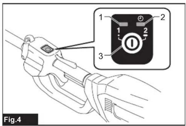
text_image
Fig.4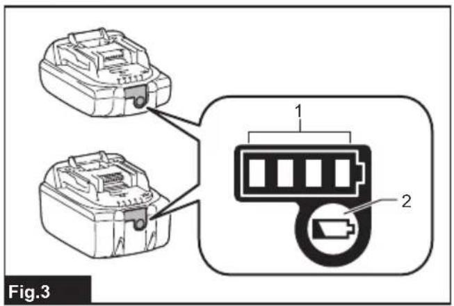
text_image
Fig.3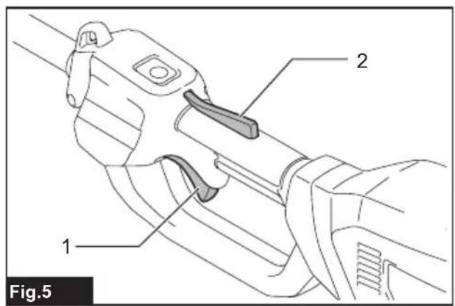
text_image
1 2 Fig.5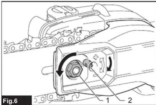
text_image
Fig.6 1 2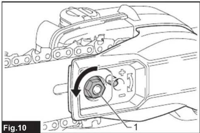
natural_image
Technical diagram of a mechanical component with labeled parts and directional arrows (no readable text or symbols)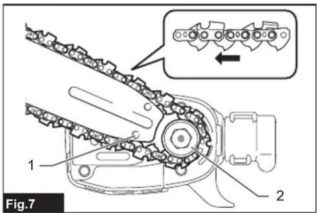
text_image
Fig.7 1 2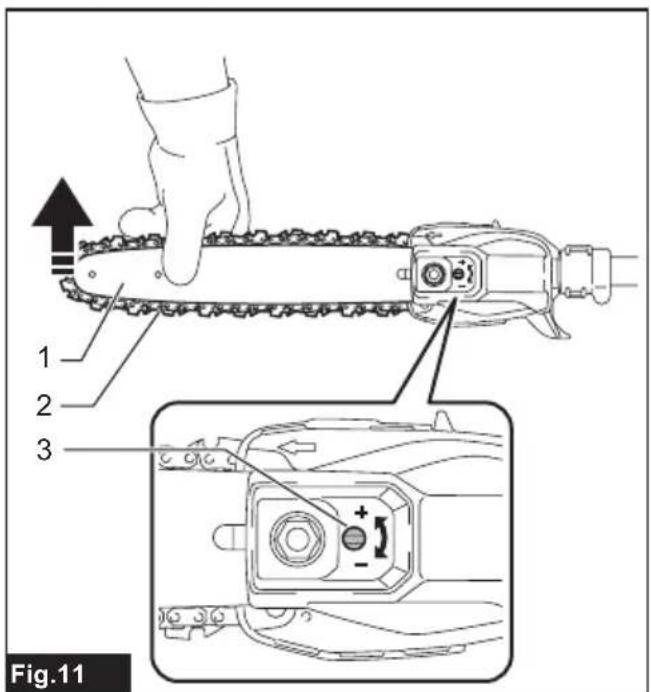
text_image
1 2 3 Fig.11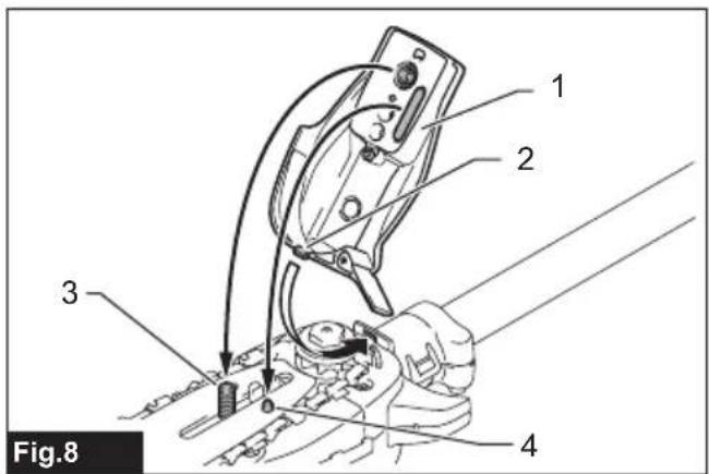
text_image
1 2 3 4 Fig.8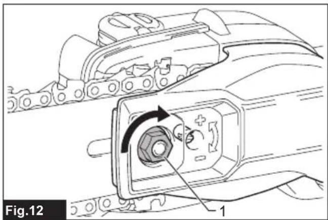
natural_image
Technical diagram of a mechanical component with labeled parts and directional arrow (no readable text or symbols)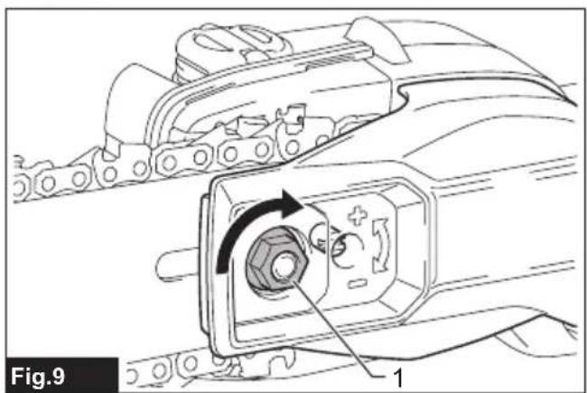
natural_image
Technical diagram of a mechanical component with labeled parts and directional arrow (no readable text or symbols)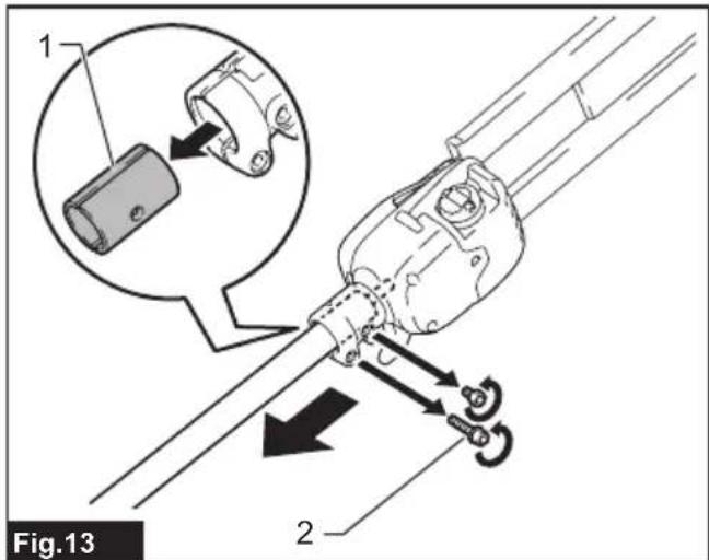
text_image
1 2 Fig.13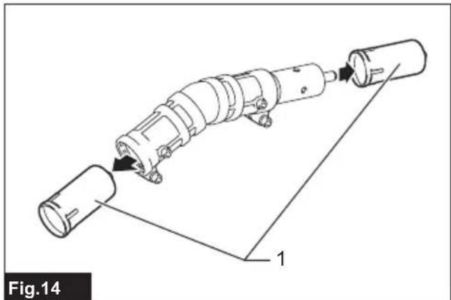
natural_image
Technical line drawing of a mechanical assembly with labeled components (no text or symbols)
text_image
Fig.15
text_image
1 Fig.16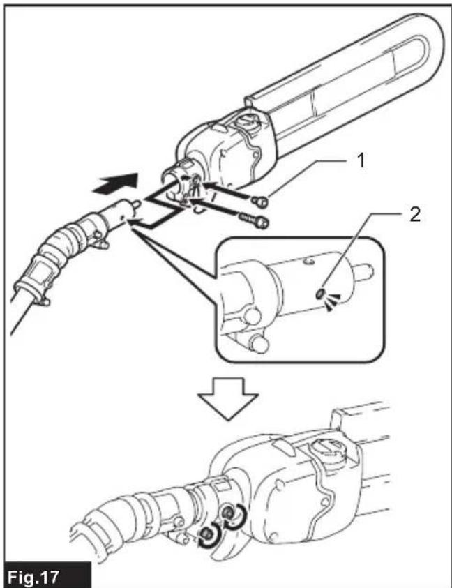
text_image
Fig.17
text_image
1 2 Fig.18
natural_image
Technical diagram of a mechanical assembly showing internal components and a close-up view of a component labeled '1', with no readable text or symbols.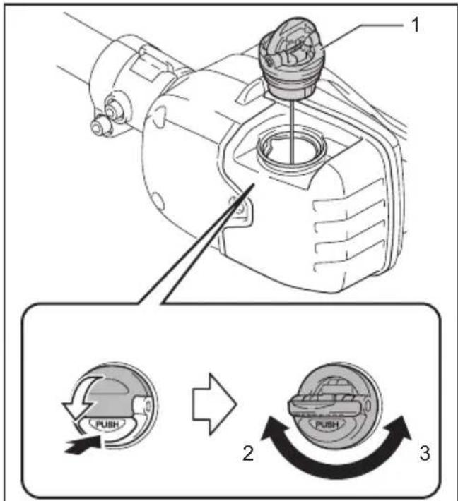
text_image
Technical diagram showing mechanical assembly with labeled parts and three circular component diagrams illustrating rotation and adjustment.Fig.20
text_image
Fig.21 1 2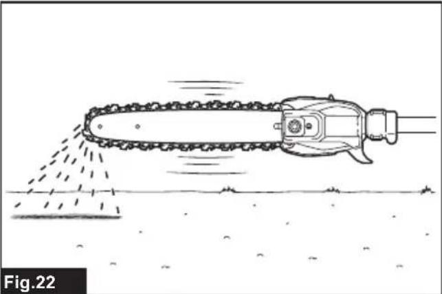
natural_image
Line drawing of a chain-linking tool spraying water onto a surface, labeled Fig.22 (no text or symbols on the diagram itself)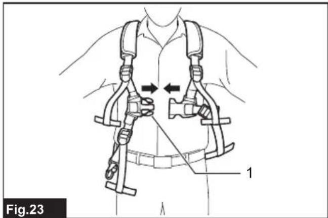
text_image
Fig.23 1
text_image
Fig.24
text_image
Fig.25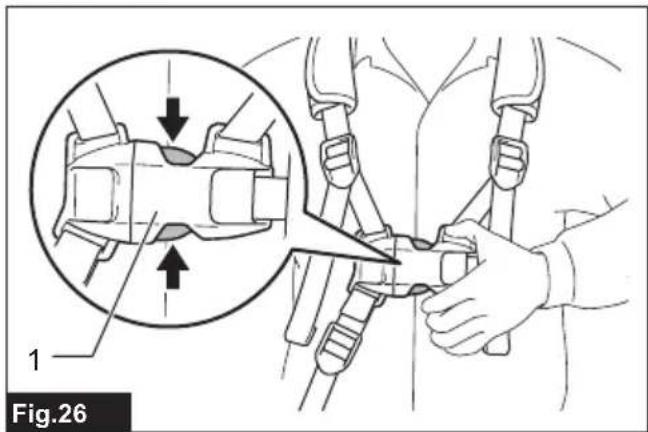
text_image
1 Fig.26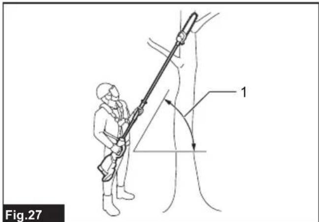
text_image
Fig.27 1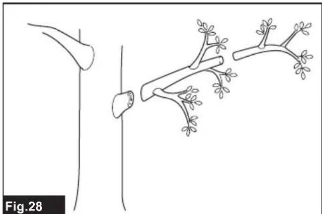
natural_image
Diagram showing a plant stem with leaves and branches, labeled Fig.28 (no text or symbols on the diagram itself)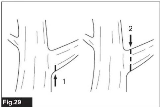
text_image
Fig.29 1 2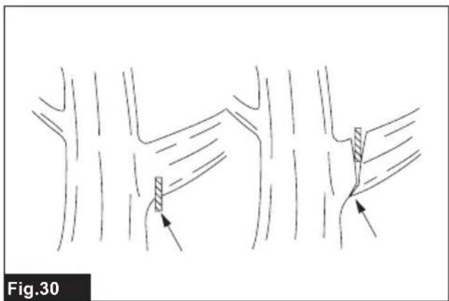
natural_image
Diagram showing two hand positions with arrows indicating movement or force, no text or symbols present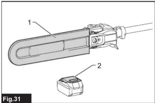
text_image
1 2 Fig.31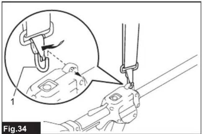
text_image
Fig.34
text_image
Fig.32 1 2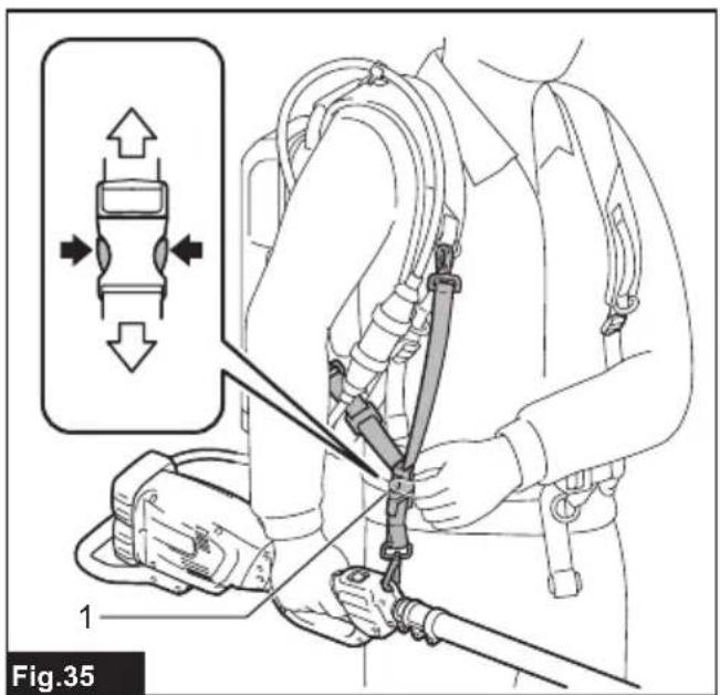
text_image
Fig.35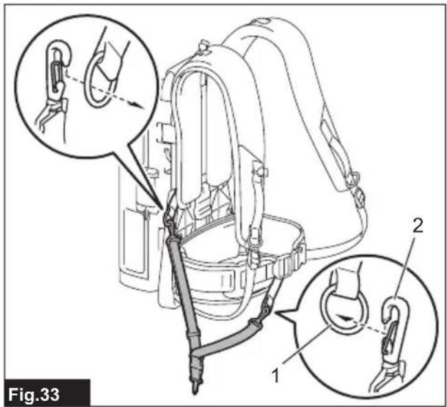
text_image
Fig.33 1 2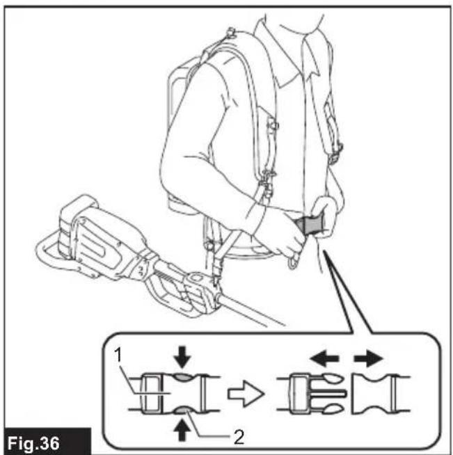
text_image
Fig.36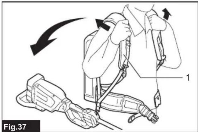
text_image
Fig.37
text_image
1 30° 1/5 Fig.41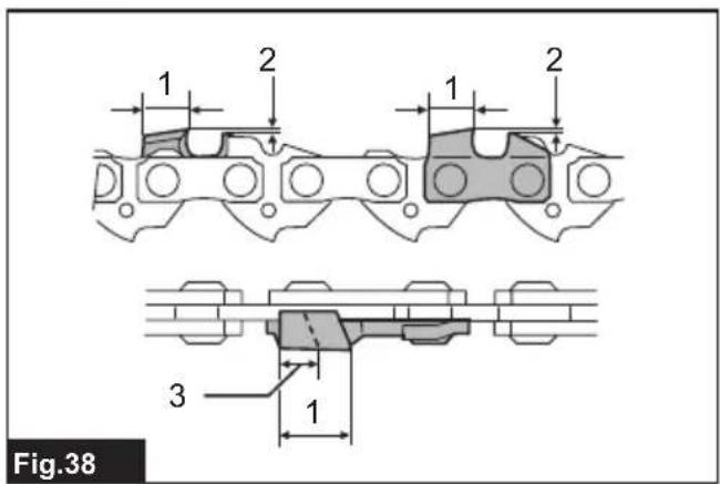
text_image
1 2 1 2 3 1 Fig.38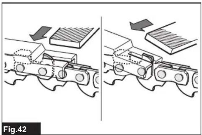
natural_image
Diagram showing two mechanical assembly steps with arrows indicating motion, no text or symbols present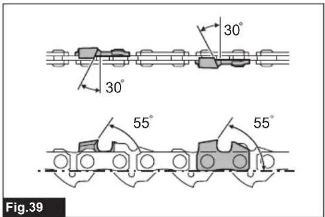
text_image
30° 30° 55° 55° Fig.39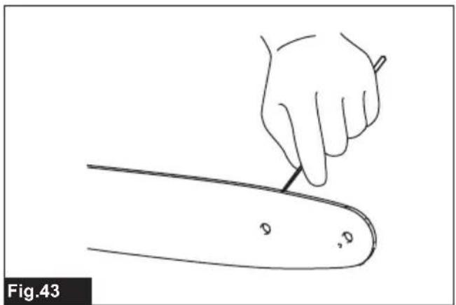
natural_image
Line drawing of a hand holding a pen over a curved object, labeled Fig.43 (no text or symbols on the diagram itself)
text_image
Fig.40 1 2 90°
natural_image
Technical line drawing of a mechanical device with a tool inserted, showing internal components and no visible text or symbols.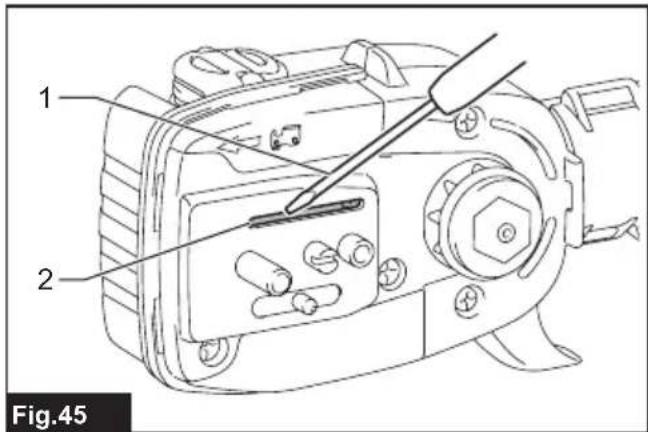
text_image
1 2 Fig.45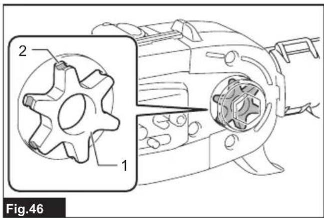
text_image
2 1 Fig.46SPECIFICATIONS
| Model: DUA300 | ||
| Overall length (without guide bar and attachment) 2,235 mm | ||
| Rated voltage D.C. 36 V | ||
| Net weight *1 6.2 kg | ||
| *2 6.1 - 7.4 kg | ||
| Standard guide bar length 30 cm | ||
| Recommended guide bar length | with 90PX / 91PX / M41 / M43 25 - 30 cm | |
| Applicable saw chain type (refer to the table below) | 90PX / 91PX / M41 / M43 | |
| Chain speed 0 - 20 m/s | (0 - 1,200 m/min) | |
| Chain oil tank volume 160 cm | 3 | |
- Due to our continuing program of research and development, the specifications herein are subject to change without notice.
• Specifications may differ from country to country.
*1: Weight, with largest battery cartridge and empty oil tank, and without guide bar, chain, shoulder harness, and attachment, according to EN ISO11680-1.
*2: The lightest and heaviest combination of weight, according to EPTA-Procedure 01/2014. The weight may differ depending on the attachment(s), including the battery cartridge.
Applicable battery cartridge and charger
| Battery cartridge BL1820B / BL1830B / BL1840B / BL1850B / BL1860B | |
| Charger | DC18RC / DC18RD / DC18RE / DC18SD / DC18SE / DC18SF / DC18SH / DC18WC |
- Some of the battery cartridges and chargers listed above may not be available depending on your region of residence.
⚠ WARNING: Only use the battery cartridges and chargers listed above. Use of any other battery cartridges and chargers may cause injury and/or fire.
Recommended cord connected power source
| Portable power pack | PDC01 / PDC1200 / PDC1500 |
- The cord connected power source(s) listed above may not be available depending on your region of residence.
- Before using the cord connected power source, read instruction and cautionary markings on them.
Saw chain, guide bar, and sprocket combination
| Saw chain type | 90PX / M41 | ||
| Number of drive links | 40 | 46 | |
| Guide bar | Guide bar length | 25 cm | 30 cm |
| Cutting length | 240 mm | 296 mm | |
| Pitch | 3/8" | ||
| Gauge | 1.1 mm | ||
| Type | Sprocket nose bar | ||
| Sprocket | Number of teeth | 6 | |
| Pitch | 3/8" | ||
| Saw chain type | 91PX / M43 | |
| Number of drive links | 40 | 46 |
| Saw chain type 91PX / M43 | |||
| Guide bar Guide bar length 25 cm | 30 cm | ||
| Cutting length 240 mm 296 mm | |||
| Pitch 3/8" | |||
| Gauge 1.3 mm | |||
| Type Sprocket nose bar | |||
| Sprocket Number of teeth 6 | |||
| Pitch 3/8" | |||
⚠ WARNING: Use appropriate combination of the guide bar and saw chain. Otherwise personal injury may result.
Symbols
The followings show the symbols which may be used for the equipment. Be sure that you understand their meaning before use.


Ni-MH Li-ion
Only for EU countries
Due to the presence of hazardous components in the equipment, waste electrical and electronic equipment, accumulators and batteries may have a negative impact on the environment and human health. Do not dispose of electrical and electronic appliances or batteries with household waste!
In accordance with the European Directive on waste electrical and electronic equipment and on accumulators and batteries and waste accumulators and batteries, as well as their adaptation to national law, waste electrical equipment, batteries and accumulators should be stored separately and delivered to a separate collection point for municipal waste, operating in accordance with the regulations on environmental protection.
This is indicated by the symbol of the crossed-out wheeled bin placed on the equipment.


Guaranteed sound power level according to EU Outdoor Noise Directive.
Sound power level according to Australia NSW Noise Control Regulation.
Intended use
The tool is intended for pruning branches and limbs.
Noise
The typical A-weighted noise level determined according to ISO22868(ISO11680-1):
Sound pressure level (LpA) : 93 dB (A)
Sound power level (LWA): 103 dB (A)
Uncertainty (K) : 3 dB (A)
NOTE: The declared noise emission value(s) has been measured in accordance with a standard test method and may be used for comparing one tool with another.
NOTE: The declared noise emission value(s) may also be used in a preliminary assessment of exposure.
WARNING: Wear ear protection.
⚠ WARNING: The noise emission during actual use of the power tool can differ from the declared value(s) depending on the ways in which the tool is used especially what kind of workpiece is processed.
⚠ WARNING: Be sure to identify safety measures to protect the operator that are based on an estimation of exposure in the actual conditions of use (taking account of all parts of the operating cycle such as the times when the tool is switched off and when it is running idle in addition to the trigger time).
Vibration
| Left handle (Front grip) Right handle (Rear grip) Applicable standard | ||||
| ah (m/s ^2 ) Uncertainty K (m/s ^2 ) ah (m/s ^2 ) Uncertainty K (m/s ^2 ) | ||||
| 2.5 or less 1.5 2.5 or less 1.5 ISO22867(ISO11680-1) | ||||
NOTE: The declared vibration total value(s) has been measured in accordance with a standard test method and may be used for comparing one tool with another.
NOTE: The declared vibration total value(s) may also be used in a preliminary assessment of exposure.
⚠ WARNING: The vibration emission during actual use of the power tool can differ from the declared value(s) depending on the ways in which the tool is used especially what kind of workpiece is processed.
WARNING: Be sure to identify safety measures to protect the operator that are based on an estimation of exposure in the actual conditions of use (taking account of all parts of the operating cycle such as the times when the tool is switched off and when it is running idle in addition to the trigger time).
Declarations of Conformity
For European countries only
The Declarations of conformity are included in Annex A to this instruction manual.
SAFETY WARNINGS
General power tool safety warnings
⚠ WARNING Read all safety warnings, instructions, illustrations and specifications provided with this power tool. Failure to follow all instructions listed below may result in electric shock, fire and/or serious injury.
Save all warnings and instructions for future reference.
The term "power tool" in the warnings refers to your mains-operated (corded) power tool or battery-operated (cordless) power tool.
Cordless pole saw safety warnings
General precautions
- Before starting the tool, read this instruction manual to become familiar with the handling of the tool.
- Do not lend the tool to a person with
insufficient experience or knowledge regarding handling of the tool.
- When lending the tool, always attach this instruction manual.
- Do not allow children or young persons under 18 years old to use the tool. Keep them away from the tool.
- Handle the tool with the utmost care and attention.
- Never use the tool after consuming alcohol or drugs, or if feeling tired or ill.
- Never attempt to modify the tool.
- Do not use the tool in bad weather conditions, especially when there is a risk of lightning. This decreases the risk of being struck by lightning.
- National regulations may restrict of the use of the tool. Follow the regulations about handling of the tool in your country.
Personal protective equipment
- Wear safety helmet, protective goggles and protective gloves to protect yourself from flying debris or falling objects.
- Wear ear protection such as ear muffs to prevent hearing loss.
- Wear proper clothing and shoes for safe operation, such as a work overall and sturdy, non-slip shoes. Do not wear loose clothing or jewelry. Loose clothes, jewelry or long hair can be caught in moving parts.
- When handling the saw chain or adjusting the
chain tension, wear protective gloves. Saw chain can cut bare hands severely.
Work area safety
- Keep the tool at least 15 m away from electric lines and communication cables (including any branches contacting them). Touching or approaching high-voltage lines with the tool can result in death or serious injury. Watch power lines and electrical fences around the work area before starting operation.
- Operate the tool under good visibility and daylight conditions only. Do not operate the tool in darkness or fog.
- During operation, never stand on an unstable or slippery surface or a steep slope. During the cold season, beware of ice and snow and always ensure secure footing.
- During operation, keep bystanders or animals at least 15 m away from the tool. Stop the tool as soon as someone approaches.
- When working with two or more people, keep a distance of at least 15 m or more between each other, and put a supervisor.
- Before operation, examine the work area for wire fences, walls, or other solid objects. They can damage the saw chain.
Preparation
- Before assembling or adjusting the tool, switch off the tool and remove the battery cartridge.
- Before handling the saw chain or adjusting the chain tension, wear protective gloves.
- Before starting the tool, inspect the tool for damages, loose screws/nuts or improper assembly. Sharpen blunt saw chain. If the saw chain is bent or damaged, replace it. Check all control levers and switches for easy action. Clean and dry the grips.
- Never attempt to start the tool if the tool is damaged or not fully assembled. Otherwise serious injury may result.
- Adjust the shoulder harness to suit the operator's body size.
- Adjust the chain tension properly. Refill the chain oil, if necessary.
Starting the tool
- Wear the personal protective equipments before starting the tool.
- Before starting the tool, make sure that there is no person or animal in the work area.
- When installing the battery cartridge, keep the saw chain and guide bar clear of your body and other object, including the ground. The saw chain may move when starting and may cause serious injury or damage to the saw chain and/or property.
- Place the tool on firm ground. Maintain good balance and secure footing.
Operation
- In the event of an emergency, switch off the tool immediately.
- If you notice any unusual condition (e.g. noise, vibration) during operation, switch off the tool.
Do not use the tool until the cause is recognized and solved.
-
The saw chain continues to move for a short period after switching off the tool. Don't rush to contact the saw chain.
-
During operation, use the shoulder harness. Keep the tool on your right side firmly.
-
Hold the front grip with your left hand and the rear grip with your right hand, no matter you are right-hander or left-hander. Wrap your fingers and thumbs around the grips.
-
Hold the tool by insulated gripping surfaces only, because the saw chain may contact hidden wiring. A saw chain contacting a "live" wire may make exposed metal parts of the extended-reach pruner "live" and could give the operator an electric shock.
-
Never attempt to operate the tool with one hand. Loss of control may result in serious or fatal injury. To reduce the risk of injury, keep your hands and feet away from the saw chain.
-
Do not overreach. Keep proper footing and balance at all times. Watch for hidden obstacles such as tree stumps, roots and ditches to avoid stumbling. Clear fallen branches and other objects away.
-
Never work on a ladder or tree to avoid loss of control.
-
If the tool gets heavy impact or fall, check the condition before continuing work. If there is any damage or doubt, ask Makita authorized service center for the inspection and repair.
-
Do not touch the head of the tool. The head of the tool becomes hot during operation.
-
Take a rest to prevent loss of control caused by fatigue. We recommend to take a 10 to 20-minute rest every hour.
-
When you leave the tool, even if it is a short time, always switch off the tool and remove the battery cartridge. The running and unattended tool may be used by unauthorized person and cause serious accident.
-
When operating the tool, do not raise your right hand above your shoulder height.
-
During operation, never hit the saw chain against hard obstacles such stones and nails. Take particular care when cutting branches next to walls, wire fences or the like.
-
If branches get caught in the tool, always stop the tool and remove the battery cartridge. Otherwise unintentional start may cause serious injury.
-
If the saw chain becomes clogged, always switch off the tool and remove the battery cartridge before cleaning.
-
Accelerating the tool with the saw chain blocked increases the load and will damage the tool.
-
Before cutting limbs, keep an escape area away from the falling limb. First, clear obstructs such as limbs and branches from the work area. Move all tools and goods from the escape area to another safe place.
-
Before cutting branches and limbs, check
the falling direction of them, considering the condition of branches and limbs, adjoining trees, wind direction, etc. Pay full attention to the falling direction, and the rebound of the branch, which hit the ground.
- Never hold the tool at an angle of more than 60^ . Otherwise falling objects can hit the operator and cause serious injury. Never stand underneath the limb being cut.
- Pay attention to broken or bent branches. They may bounce back in cutting, causing unexpected injury.
- Before cutting limbs that you intend to cut, remove branches and leaves around them. Otherwise the saw chain may be caught by them.
- To prevent the saw chain from being caught in the kerf, do not release the lever before pulling the saw chain out of the kerf.
- If the saw chain is bound in the kerf, immediately stop the tool, carefully move the branch to open the kerf and release the saw chain.
- Avoid kickback (rotational reactive force towards the operator). To prevent kickback, never use the guide bar nose or perform a penetrating cut. Always beware of the position of the guide bar nose.
- Check the chain tension frequently. When checking or adjusting the chain tension, switch off the tool and remove the battery cartridge. If the tension is loose, tighten it.
Vibration
- Exposing to excessive vibration injures blood vessels or nervous system of the operator and causes the following symptoms in the fingers, hands or wrists: "Falling asleep" (numbness), tingling, pain, stabbing sensation, or alteration of skin color or of the skin. If any of these symptoms occur, see a physician. To reduce the risk of "white finger disease", keep your hands warm during operation and well maintain the tool and accessories. For operating time, follow your local regulations or physician's advice.
Transport
-
Before transporting the tool, switch off the tool and remove the battery cartridge. Always fit the guide bar cover during transportation.
-
When transporting the tool, carry it in a horizontal position by holding the grip.
Maintenance
- Have your equipment serviced by our authorized service center, always using only genuine replacement parts. Incorrect repair and poor maintenance can shorten the life of the tool and increase the risk of accidents.
- Before doing any maintenance or repair work or cleaning the tool, always switch off the tool and remove the battery cartridge. Wait until the tool cools down.
- Always wear protective gloves when handling the saw chain.
- After each use, tighten all screws and nuts, except for adjustment screws.
- Keep the saw chain sharp. If the saw chain
has become blunt and cutting performance is poor, ask Makita authorized service center to sharpen it or replace it with new one.
- Do not attempt any maintenance or repair not described in this instruction manual. Ask Makita authorized service center for such work.
- Always use Makita genuine spare parts and accessories only. Using parts or accessories supplied by a third party may result in the tool breakdown, property damage and/or serious injury.
Storage
- Before storing the tool, perform full cleaning and maintenance. Fit the guide bar cover. Remove the battery cartridge. Drain the chain oil after the tool cools down.
- Store the tool in a dry and high or locked location out of reach of children.
- Do not prop the tool against something, such as a wall. Otherwise it may fall suddenly and cause an injury.
Electrical and battery safety
- Do not dispose of the battery(ies) in a fire. The cell may explode. Check with local codes for possible special disposal instructions.
- Do not open or mutilate the battery(ies). Released electrolyte is corrosive and may cause damage to the eyes or skin. It may be toxic if swallowed.
- Do not charge battery in rain, or in wet locations.
- Do not charge the battery outdoors.
- Do not handle charger, including charger plug, and charger terminals with wet hands.
- Avoid dangerous environment. Don't use the tool in damp or wet locations or expose it to rain. Water entering the tool will increase the risk of electric shock.
SAVE THESE INSTRUCTIONS.
WARNING: DO NOT let comfort or familiarity with product (gained from repeated use) replace strict adherence to safety rules for the subject product. MISUSE or failure to follow the safety rules stated in this instruction manual may cause serious personal injury.
Important safety instructions for battery cartridge
- Before using battery cartridge, read all instructions and cautionary markings on (1) battery charger, (2) battery, and (3) product using battery.
- Do not disassemble or tamper with the battery cartridge. It may result in a fire, excessive heat, or explosion.
- If operating time has become excessively shorter, stop operating immediately. It may result in a risk of overheating, possible burns and even an explosion.
- If electrolyte gets into your eyes, rinse them
out with clear water and seek medical attention right away. It may result in loss of your eyesight.
- Do not short the battery cartridge:
(1) Do not touch the terminals with any conductive material.
(2) Avoid storing battery cartridge in a container with other metal objects such as nails, coins, etc.
(3) Do not expose battery cartridge to water or rain.
A battery short can cause a large current flow, overheating, possible burns and even a breakdown.
- Do not store and use the tool and battery cartridge in locations where the temperature may reach or exceed 50 °C (122 °F).
- Do not incinerate the battery cartridge even if it is severely damaged or is completely worn out. The battery cartridge can explode in a fire.
- Do not nail, cut, crush, throw, drop the battery cartridge, or hit against a hard object to the battery cartridge. Such conduct may result in a fire, excessive heat, or explosion.
- Do not use a damaged battery.
- The contained lithium-ion batteries are subject to the Dangerous Goods Legislation requirements.
For commercial transports e.g. by third parties, forwarding agents, special requirement on packaging and labeling must be observed.
For preparation of the item being shipped, consulting an expert for hazardous material is required.
Please also observe possibly more detailed national regulations.
Tape or mask off open contacts and pack up the battery in such a manner that it cannot move around in the packaging.
- When disposing the battery cartridge, remove it from the tool and dispose of it in a safe place. Follow your local regulations relating to disposal of battery.
- Use the batteries only with the products specified by Makita. Installing the batteries to non-compliant products may result in a fire, excessive heat, explosion, or leak of electrolyte.
- If the tool is not used for a long period of time,
the battery must be removed from the tool.
- During and after use, the battery cartridge may take on heat which can cause burns or low temperature burns. Pay attention to the handling of hot battery cartridges.
- Do not touch the terminal of the tool immediately after use as it may get hot enough to cause burns.
- Do not allow chips, dust, or soil stuck into the terminals, holes, and grooves of the battery cartridge. It may cause heating, catching fire, burst and malfunction of the tool or battery cartridge, resulting in burns or personal injury.
- Unless the tool supports the use near high-voltage electrical power lines, do not use the battery cartridge near high-voltage electrical power lines. It may result in a malfunction or breakdown of the tool or battery cartridge.
- Keep the battery away from children.
SAVE THESE INSTRUCTIONS.
CAUTION: Only use genuine Makita batteries.
Use of non-genuine Makita batteries, or batteries that have been altered, may result in the battery bursting causing fires, personal injury and damage. It will also void the Makita warranty for the Makita tool and charger.
Tips for maintaining maximum battery life
- Charge the battery cartridge before completely discharged. Always stop tool operation and charge the battery cartridge when you notice less tool power.
- Never recharge a fully charged battery cartridge. Overcharging shortens the battery service life.
- Charge the battery cartridge with room temperature at 10 °C - 40 °C ( 50 °F - 104 °F ). Let a hot battery cartridge cool down before charging it.
- When not using the battery cartridge, remove it from the tool or the charger.
- Charge the battery cartridge if you do not use it for a long period (more than six months).
PARTS DESCRIPTION
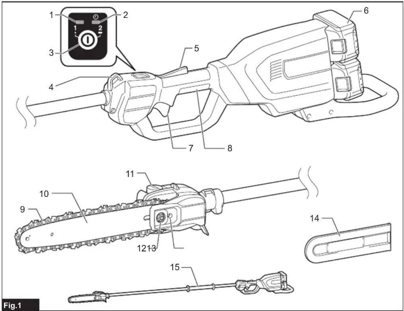
▶ Fig.1
| 1 | Main power lamp | 2 | Mode indicator | 3 | Main power switch |
| 4 | Hanger | 5 | Lock-off lever | 6 | Battery cartridge |
| 7 | Switch trigger | 8 | Rear grip | 9 | Saw chain |
| 10 | Guide bar | 11 | Oil tank cap | 12 | Retaining nut |
| 13 | Chain adjusting screw | 14 | Guide bar cover | 15 | Front grip |
FUNCTIONAL DESCRIPTION
⚠️CAUTION: Always be sure that the tool is switched off and the battery cartridge is removed before adjusting or checking function on the tool.
Installing or removing battery cartridge
⚠️CAUTION: Always switch off the tool before installing or removing of the battery cartridge.
⚠️CAUTION: Hold the tool and the battery cartridge firmly when installing or removing battery cartridge. Failure to hold the tool and the battery cartridge firmly may cause them to slip off your hands and result in damage to the tool and battery cartridge and a personal injury.
To install the battery cartridge, align the tongue on the battery cartridge with the groove in the housing and slip it into place. Insert it all the way until it locks in place with a little click. If you can see the red indicator as shown in the figure, it is not locked completely.
To remove the battery cartridge, slide it from the tool while sliding the button on the front of the cartridge. ▶ Fig.2: 1. Red indicator 2. Button 3. Battery cartridge
CAUTION: Always install the battery cartridge fully until the red indicator cannot be seen. If not, it may accidentally fall out of the tool, causing injury to you or someone around you.
⚠️CAUTION: Do not install the battery cartridge forcibly. If the cartridge does not slide in easily, it is not being inserted correctly.
Indicating the remaining battery capacity
Only for battery cartridges with the indicator
Press the check button on the battery cartridge to indicate the remaining battery capacity. The indicator lamps light up for a few seconds.
▶ Fig.3: 1. Indicator lamps 2. Check button
| Indicator lamps Remaining | capacity | ||
| Lighted Off | Blinking | ||
| 75% to 100% | |||
| 50% to 75% | |||
| 25% to 50% | |||
| 0% to 25% | |||
| Charge the battery. | |||
| Indicator lamps Remaining | capacity | ||
| Lighted Off | Blinking | ||
| The battery may have malfunctioned. | |||
NOTE: Depending on the conditions of use and the ambient temperature, the indication may differ slightly from the actual capacity.
NOTE: The first (far left) indicator lamp will blink when the battery protection system works.
Tool / battery protection system
The tool is equipped with a tool/battery protection system. This system automatically cuts off power to the motor to extend tool and battery life. The tool will automatically stop during operation if the tool or battery is placed under one of the following conditions:
Overload protection
When the battery is operated in a manner that causes it to draw an abnormally high current, the tool automatically stops and the main power lamp blinks in green. In this situation, turn the tool off and stop the application that caused the tool to become overloaded. Then turn the tool on to restart.
Overheat protection
When the tool or battery is overheated, the tool stops automatically and the main power lamp lights up in red. In this case, let the tool and battery cool before turning the tool on again.
NOTE: In high temperature environment, the over-heat protection likely to work and the tool stops automatically.
Overdischarge protection
When the battery capacity is not enough, the tool stops automatically and the main power lamp blinks in red. In this case, remove the battery from the tool and charge the battery.
Main power switch
⚠ WARNING: Always turn off the main power switch when not in use.
To turn on the tool, press the main power switch until the main power lamp lights up in green. To turn off, press the main power switch again.
▶ Fig.4: 1. Main power lamp 2. Mode indicator 3. Main power switch
NOTE: The main power lamp blinks in green when you turn on the main power switch while holding down the lock-off lever and pulling the switch trigger. In this case, release the switch trigger and the lock-off lever, and then turn on the main power switch.
NOTE: This tool employs the auto power-off function. To avoid unintentional start up, the main power switch will automatically shut down when the switch trigger is not pulled for a certain period after the main power switch is turned on.
You can use the tool in the Torque Boost mode for cutting thick branches or hard branches. To use the tool in the Torque Boost mode, when the tool is turned off, press the main power switch for a few seconds until the mode indicator lights up in green.
NOTE: You can use the tool in the Torque Boost mode up to 60 seconds. Depending on the usage conditions, this mode shifts to the normal mode in less than 60 seconds.
NOTE: If the mode indicator blinks in green when you press the main power switch for a few seconds, the Torque Boost mode is not available. In this case, follow the steps below.
- The Torque Boost mode is not available right after the cutting operation. Wait for more than 10 seconds, and then press the main power switch for a few seconds again.
- If you use the Torque Boost mode several times, the use of the Torque Boost mode is restricted to protect the battery. If the Torque Boost mode is not available after waiting for more than 10 seconds, replace the battery cartridge with a fully charged one, or recharge the battery cartridge.
NOTE: If the main power lamp lights up in red or blinks in red or green, refer to the instructions for tool/battery protection system.
Switch action
WARNING: For your safety, this tool is equipped with lock-off lever which prevents the tool from unintended starting. NEVER use the tool if it runs when you simply pull the switch trigger without pressing the lock-off lever. Return the tool to our authorized service center for proper repairs BEFORE further usage.
⚠ WARNING: NEVER tape down or defeat purpose and function of lock-off lever.
⚠️CAUTION: Before installing the battery cartridge into the tool, always check to see that the switch trigger actuates properly and returns to the "OFF" position when released.
NOTICE: Do not pull the switch trigger hard without pressing the lock-off lever. This can cause switch breakage.
To prevent the switch trigger from being accidentally pulled, a lock-off lever is provided. To start the tool, depress the lock-off lever and pull the switch trigger. The tool speed increases by increasing pressure on the switch trigger. Release the switch trigger to stop.
▶ Fig.5: 1. Switch trigger 2. Lock-off lever
Electronic function
The tool is equipped with the electronic functions for easy operation.
- Constant speed control
The speed control function provides the constant rotation speed regardless of load conditions.
ASSEMBLY
CAUTION: Always be sure that the tool is switched off and the battery cartridge is removed before carrying out any work on the tool.
CAUTION: Do not touch the saw chain with bare hands. Always wear gloves when handling the saw chain.
Removing or installing saw chain
CAUTION: The saw chain and the guide bar are still hot just after the operation. Let them cool down enough before carrying out any work on the tool.
CAUTION: Carry out the procedure of installing or removing saw chain in a clean place free from sawdust and the like.
To remove the saw chain, perform the following steps:
- Loosen the chain adjusting screw, then the retaining nut.
▶ Fig.6: 1. Retaining nut 2. Chain adjusting screw
2. Remove the sprocket cover, and then remove the saw chain and guide bar from the tool body.
To install the saw chain, perform the following steps:
- Check the direction of the saw chain. Match the direction of the saw chain with that of the mark on the tool body.
- Fit one end of the saw chain on the top of the guide bar. Fit the other end of the saw chain around the sprocket. Make sure that the saw chain is properly fitted on the sprocket and properly fitted in the groove of the guide bar.
- Attach the guide bar to the tool body, aligning the hole on the guide bar with the pin on the tool body.
▶ Fig.7: 1. Hole 2. Sprocket
- Insert the protrusion on the sprocket cover to the tool body, and then close the cover so that the bolt and pin on the tool body meet their counterparts on the cover.
▶ Fig.8: 1. Sprocket cover 2. Protrusion 3. Bolt 4. Pin - Tighten the retaining nut to secure the sprocket cover, then loosen it a bit for tension adjustment.
▶ Fig.9: 1. Retaining nut
Adjusting saw chain tension
⚠CAUTION: Do not tighten the saw chain too much. Excessively high tension of saw chain may cause breakage of saw chain and wear of the guide bar.
⚠️CAUTION: A chain which is too loose can jump off the bar and it may cause an injury accident.
The saw chain may become loose after many hours of use. From time to time check the saw chain tension before use.
- Loosen the retaining nut a bit to loosen the sprocket cover lightly.
▶ Fig.10: 1. Retaining nut - Lift up the guide bar tip slightly and adjust the chain tension. Turn the chain adjusting screw counterclockwise to tighten, turn it clockwise to loosen.
Tighten the saw chain until the lower side of the saw chain fits in the guide bar rail as illustrated.
▶ Fig.11: 1. Guide bar 2. Saw chain 3. Chain adjusting screw
- Keep holding the guide bar lightly and attach the sprocket cover.
Make sure that the saw chain does not loose at the lower side. - Tighten the retaining nut to secure the sprocket cover.
▶ Fig.12: 1. Retaining nut
Installing or removing the angled attachment
Optional accessory
⚠️CAUTION: Before installing or removing the angled attachment, be sure to attach the guide bar cover to the tool.
You can change the angle of the tool head by attaching the angled attachment to the tool.
- Attach the guide bar cover to the tool.
- Loosen 2 bolts with the hex wrench, and then remove the pipe and sleeves from the head of the tool.
▶ Fig.13: 1. Sleeve 2. Bolt
- Remove the caps from the angled attachment.
▶ Fig.14: 1. Cap -
Align the hole on the sleeve with that on the pipe, and then attach 2 sleeves to the pipe. Align the hole on the sleeve with that on the attachment, and then insert the pipe into the attachment.
▶ Fig.15: 1. Hole 2. Bolt 3. Sleeve 4. Pipe -
Tighten 2 bolts to fix the attachment.
▶ Fig.16: 1. Bolt
- Attach the head of the tool to the attachment.
To fix the head of the tool vertically, fix the attachment by tightening the bolt to the hole on the attachment shown in the figure, and then tighten the other bolt.
▶ Fig.17: 1. Bolt 2. Hole
To fix the head of the tool horizontally, fix the attachment by tightening the bolt to the hole on the attachment shown in the figure, and then tighten the other bolt.
▶ Fig.18: 1. Bolt 2. Hole
To remove the angled attachment, perform the installation procedure in reverse.
OPERATION
Lubrication
NOTICE: When filling the chain oil for the first time, or refilling the tank after it has been completely emptied, add oil up to the bottom edge of the filler neck. The oil delivery may otherwise be impaired.
NOTICE: Use the saw chain oil exclusively for Makita chain saws or equivalent oil available in the market.
NOTICE: Never use oil including dust and particles or volatile oil.
NOTICE: When pruning trees, use botanical oil. Mineral oil may harm trees.
NOTICE: Before the cutting operation, make sure that the oil tank cap is tightened securely.
Saw chain is automatically lubricated when the tool is in operation. Check the amount of remaining oil in the oil tank periodically.
▶ Fig.19: 1. Oil tank
To refill the tank, place the tool on a flat surface, then push the button on the oil tank cap so that the button on the other side stands up, and then remove the oil tank cap by turning it.
The proper amount of oil is 160 ml. After refilling the tank, make sure that the oil tank cap is tightened securely.
▶ Fig.20: 1. Oil tank cap 2. Tighten 3. Loosen
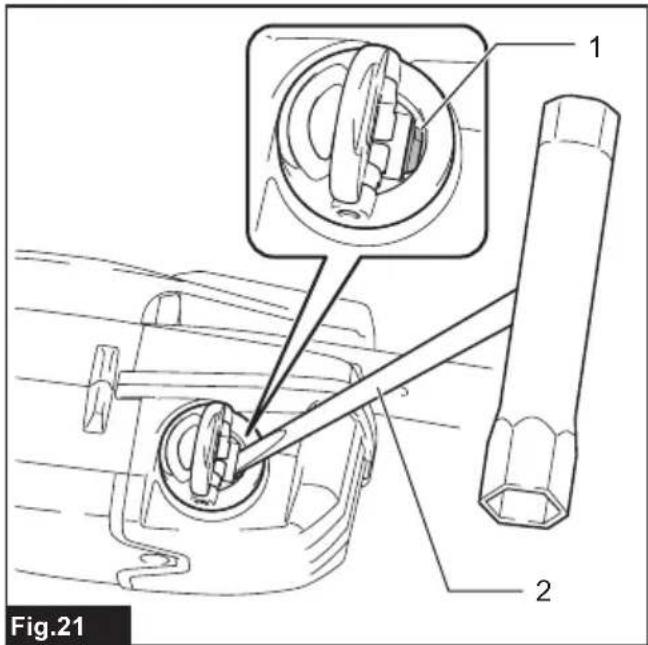
NOTE: If it is difficult to remove the oil tank cap, insert the box wrench into the slot of the oil tank cap, and then remove the oil tank cap by turning it counterclockwise.
▶ Fig.21: 1. Slot 2. Box wrench
After refilling, hold the tool away from the tree. Start it and wait until lubrication on saw chain is adequate.
▶ Fig.22
Attaching the shoulder harness
⚠CAUTION: When you use the tool in combination of the backpack-type power supply such as portable power pack, do not use the shoulder harness included in the tool package, but use the hanging band recommended by Makita.
If you put on the shoulder harness included in the tool package and the shoulder harness of the backpack-type power supply at the same time, removing the tool or backpack-type power supply is difficult in case of an emergency, and it may cause an accident or injury. For the recommended hanging band, ask Makita Authorized Service Centers.
⚠CAUTION: Always use the shoulder harness attached to the tool. Before operation, adjust the shoulder harness according to the user size to prevent fatigue.
⚠️CAUTION: Before operation, make sure that the shoulder harness is properly attached to the hanger on the tool.
⚠️CAUTION: Before operation, make sure that the buckle of the shoulder harness is fastened firmly.
⚠CAUTION: Always use the shoulder harness dedicated to this tool. Do not use other shoulder harnesses.
- Put on the shoulder harness and fasten the buckle.
▶ Fig.23: 1. Buckle
NOTE: When removing the shoulder harness, unlock the buckle and remove the shoulder harness.
- Adjust the shoulder harness to a comfortable working position.
▶ Fig.24 - Clasp the hook on the shoulder harness to tool's hanger.
▶ Fig.25: 1. Hook 2. Hanger
The shoulder harness features a means of quick release. Simply squeeze the sides of the buckle to release the shoulder harness.
▶ Fig.26: 1. Buckle
Working with the tool
CAUTION: Keep all parts of the body away from the saw chain when the motor is operating.
CAUTION: Hold the tool firmly with both hands when the motor is running.
CAUTION: Do not overreach. Keep proper footing and balance at all times.
⚠️ CAUTION: When cutting through branches, be careful not to lose your balance due to the weight of the tool head.
CAUTION: Always keep escape route in case a cut branch falls towards the operator.
CAUTION: Never use the tip of the guide bar for cutting. Otherwise, dangerous kickback may occur, and it may result in personal injury.
NOTICE: Never toss or drop the tool.
NOTICE: Do not cover the vents of the tool.
NOTICE: Do not force the tool. Otherwise, it may damage the tool.
Stand on a stable surface, and hold the tool away from the branches so that the angle of the tool becomes 60^ or less against the horizontal ground.
▶ Fig.27: 1.60° or less
Start the tool, and then press the saw chain onto the branch lightly.
When cutting long branches, in order to control the drop position of cut branches, divide the branch in sections and cut the branch from the tip. Pay attention to the falling branches since they may bounce in the direction of the operator after hitting the ground.
▶ Fig.28
When cutting thick branches, first make a shallow undercut and then make the finish cut from the top.
▶ Fig.29
If you try to cut off thick branches from the bottom, the branch may close in and pinch the saw chain in the cut. If you try to cut off thick branches from the top without a shallow undercut, the branch may splinter.
▶ Fig.30
Carrying tool
Before carrying the tool, always remove the battery cartridges from the tool, and then attach the guide bar cover. Also cover the battery cartridge with the battery cover.
▶ Fig.31: 1. Guide bar cover 2. Battery cover
Using the tool with portable power pack
Optional accessory
Use the hanging band when you use the tool with portable power pack.
Attaching the hanging band
- Attach the hooks of the hanging band to the rings of the shoulder harness or waist belt as shown in the figure. Select the type of band and the connecting method appropriate for your usage.
▶ Fig.32: 1. Ring 2. Hook
▶ Fig.33: 1. Ring 2. Hook
2. Attach the hook to the tool.
▶ Fig.34: 1. Hook
Detaching the tool
When setting down the tool, unlock the buckle on the hanging band with one hand while holding the tool with the other hand.
▶ Fig.35: 1. Buckle
NOTE: The buckle is not equipped depending on the type of band.
If you need to release the tool quickly, follow the steps below.
- Push the levers on the buckle of the waist belt to unlock the buckle.
▶ Fig.36: 1. Buckle 2. Lever - Take off the shoulder harness to release the tool and the unit.
▶ Fig.37: 1. Shoulder harness
MAINTENANCE
⚠️CAUTION: Always be sure that the tool is switched off and the battery cartridge is removed before attempting to perform inspection or maintenance.
⚠️CAUTION: Always wear gloves when performing any inspection or maintenance.
NOTICE: Never use gasoline, benzine, thinner, alcohol or the like. Discoloration, deformation or cracks may result.
To maintain product SAFETY and RELIABILITY, repairs, any other maintenance or adjustment should be performed by Makita Authorized or Factory Service Centers, always using Makita replacement parts.
Sharpening the saw chain
Sharpen the saw chain when:
- Mealy sawdust is produced when damp wood is cut;
- The chain penetrates the wood with difficulty, even when heavy pressure is applied;
- The cutting edge is obviously damaged;
- The saw pulls to the left or right in the wood. (caused by uneven sharpening of the saw chain or damage to one side only)
Sharpen the saw chain frequently but a little each time. Two or three strokes with a file are usually sufficient for routine resharpening. When the saw chain has been resharpened several times, have it sharpened in our authorized service center.
Sharpening criteria:
⚠ WARNING: An excessive distance between the cutting edge and depth gauge increases the risk of kickback.
▶ Fig.38: 1. Cutter length 2. Distance between cutting edge and depth gauge 3. Minimum cutter length (3 mm)
— All cutter length must be equal. Different cutter lengths prevent the saw chain from running smoothly and may cause the saw chain to break.
— Do not sharpen the chain when the cutter length has reached 3 mm or shorter. The chain must be replaced with new one.
— The chip thickness is determined by the distance between the depth gauge (round nose) and the cutting edge.
— The best cutting results are obtained with following distance between cutting edge and depth gauge.
- Chain blade 90PX / 91PX / M41 / M43 : 0.65 mm
▶ Fig.39
— The sharpening angle of 30^ must be the same on all cutters. Different cutter angles cause the chain to run roughly and unevenly, accelerate wear, and lead to chain breaks.
— Use a suitable round file so that the proper sharpening angle is kept against the teeth.
- Chain blade 90PX / 91PX / M41 / M43 : 55°
File and file guiding
— Use a special round file (optional accessory) for saw chains to sharpen the chain. Normal round files are not suitable.
— Diameter of the round file for each saw chain is as follows:
- Chain blade 90PX : 4.5 mm
- Chain blade 91PX / M41/ M43 : 4.0 mm
— The file should only engage the cutter on the forward stroke. Lift the file off the cutter on the return stroke.
— Sharpen the shortest cutter first. Then the length of this shortest cutter becomes the standard for all other cutters on the saw chain.
— Guide the file as shown in the figure.
▶ Fig.40: 1. File 2. Saw chain
— The file can be guided more easily if a file holder (optional accessory) is employed. The file holder has markings for the correct sharpening angle of 30^ (align the markings parallel to the saw chain) and limits the depth of penetration (to 4/5 of the file diameter).
▶ Fig.41: 1. File holder
— After sharpening the chain, check the height of the depth gauge using the chain gauge tool (optional accessory).
▶ Fig.42
— Remove any projecting material, however small, with a special flat file (optional accessory).
— Round off the front of the depth gauge again.
Cleaning the guide bar
Chips and sawdust will build up in the guide bar groove. They may clog the bar groove and impair the oil flow. Clean out the chips and sawdust every time when you sharpen or replace the saw chain.
▶ Fig.43
Cleaning the sprocket cover
Chips and saw dust will accumulate inside of the sprocket cover. Remove the sprocket cover and saw chain from the tool then clean the chips and saw dust.
▶ Fig.44
Cleaning the oil discharge hole
Small dust or particles may be built up in the oil discharge hole during operation. These dust or particles may impair the oil to flow and cause an insufficient lubrication on the whole saw chain. When a poor chain oil delivery occurs at the top of guide bar, clean the oil discharge hole as follows.
- Remove the sprocket cover and saw chain from the tool.
- Remove the small dust or particles using a slotted screwdriver or the like.
▶ Fig.45: 1. Slotted screwdriver 2. Oil discharge hole
- Insert the battery cartridge into the tool. Pull the switch trigger to flow built-up dust or particles off the oil discharge hole by discharging chain oil.
- Remove the battery cartridge from the tool. Reinstall the sprocket cover and saw chain on the tool.
Replacing the sprocket
⚠️ CAUTION: A worn sprocket will damage a new saw chain. Have the sprocket replaced in this case.
Before fitting a new saw chain, check the condition of the sprocket. If the sprocket is worn or damaged, ask Makita Authorized Service Centers for replacement.
▶ Fig.46: 1. Sprocket 2. Areas to be worn out
Storing the tool
- Clean the tool before storing. Remove any chips and sawdust from the tool after removing the sprocket cover.
- After cleaning the tool, run it under no load to lubricate the saw chain and guide bar.
- Cover the guide bar with the guide bar cover.
- Empty the oil tank.
Instructions for periodic maintenance
To ensure long life, prevent damage and ensure the full functioning of the safety features, the following maintenance must be performed regularly. Warranty claims can be recognized only if this work is performed regularly and properly. Failure to perform the prescribed maintenance work can lead to accidents! The user of the tool must not perform maintenance work which is not described in the instruction manual. All such work must be carried out by our authorized service center.
| Check item / Operating time Before operation | Everyday Every week Every 3 month | Annually Before storage | ||||
| Entire tool Inspection. | √ | ---- | ||||
| Cleaning. - | √ | ---- | ||||
| Check at authorized service center. | ---- | √ | ||||
| Saw chain Inspection. ---- | √ | |||||
| Sharpening if necessary. | ---- | |||||
| Guide bar Inspection. ---- | √ | √ | ||||
| Remove from the tool. | ---- | |||||
| Chain lubrication | Check the oil feed rate. | √ | ---- | |||
| Switch trigger | Inspection. | √ | ---- | |||
| Lock-off lever | Inspection. | √ | ---- | |||
| Oil tank cap | Check tightness. | √ | ---- | |||
| Screws and nuts | Inspection. | -- | √ | ---- | ||
TROUBLESHOOTING
Before asking for repairs, conduct your own inspection first. If you find a problem that is not explained in the manual, do not attempt to dismantle the tool. Instead, ask Makita Authorized Service Centers, always using Makita replacement parts for repairs.
| Malfunction status Cause Action | ||
| The tool does not start. Battery cartridge is not installed. Install a charged battery cartridge. | ||
| Battery problem (low voltage). | ||
| Main power switch is off. The tool is automatically turned off if it is un-operated for a certain period. Turn on the main power switch again. | ||
| The motor stops running after a little use. | Battery's charge level is low. | Recharge the battery cartridges. If recharging is not effective, replace the battery cartridge. |
| No oil on the chain. Oil tank is empty. Fill the oil tank. | ||
| Oil guide groove is dirty. Clean the groove. | ||
| Poor oil delivery. Adjust the amount of oil delivery with the adjusting screw. | ||
| The tool does not reach maximum RPM. | Battery cartridge is installed improperly. | Install the battery cartridges as described in this manual. |
| Battery power is dropping. | Recharge the battery cartridge. If recharging is not effective, replace the battery cartridge. | |
| The drive system does not work correctly. | Ask the authorized service center in your region for repair. | |
| The main power lamp is blinking in green. | Switch trigger is pulled under an unoperatable condition. | Pull the switch trigger after the main power switch is turned on. |
| Abnormal vibration:Stop the tool immediately! | Loose guide bar or saw chain. Adjust the guide bar and saw chain tension. | |
| Tool malfunction. Ask the authorized service center in your region for repair. | ||
| The Torque Boost mode is not available after replacing the battery cartridge with a fully charged one. | Depending on the usage conditions, the Torque Boost mode is not available after replacing the battery cartridge. | Use the tool in the normal mode until the installed battery cartridge becomes empty, and then replace the battery cartridge with a fully charged one, or recharge the battery cartridge. |
| The saw chain cannot be installed. | The combination of saw chain and sprocket is not correct. | Use the correct combination of saw chain and sprocket by referring to the section for specifications. |
OPTIONAL ACCESSORIES
⚠️CAUTION: These accessories or attachments are recommended for use with your Makita tool specified in this manual. The use of any other accessories or attachments might present a risk of injury to persons. Only use accessory or attachment for its stated purpose.
If you need any assistance for more details regarding these accessories, ask your local Makita Service Center.
- Saw chain
- Guide bar
• Guide bar cover -
Angled attachment
-
File
• Makita genuine battery and charger
⚠ WARNING: If you purchase a guide bar of different length from the standard guide bar, also purchase a suitable guide bar cover together. It must fit and fully cover the guide bar on the tool.
NOTE: Some items in the list may be included in the tool package as standard accessories. They may differ from country to country.
SPÉCIFICATIONS
▶ Fig.36: 1. Boucle 2. Levier
▶ Abb.17: 1. Schraube 2. Loch
▶ Abb.21: 1. Schlitz 2. Rohrschlüssel
▶ Abb.23: 1. Schnalle
▶ Abb.26: 1. Schnalle
VEILIGHEIDSWAAR- SCHUWINGEN
▶ Fig.13: 1. Bus 2. Bout
▶ Fig.27: 1. 60° of minder
OPTIONELE ACCESSOIRES
▶ Fig.7: 1. Agujero 2. Piñón
- Remova as tampas do acessório angular.
▶ Fig.14: 1. Tampa
▶ Eik.14: 1. Kappáki