598446 - Grinder SILVERLINE - Free user manual and instructions
Find the device manual for free 598446 SILVERLINE in PDF.
| Product type | Right-angle pneumatic grinder |
| Brand | Silverline |
| Model | 598446 |
| Maximum working pressure | 6.3 bar |
| Air consumption | 170 L/min |
| Air inlet | 1/4 BSP connection with two quick couplings (EN-6 and EQ-4) |
| Minimum hose diameter | 9.5 mm |
| No-load speed | 20 000 min⁻¹ |
| Disc dimensions | 75 × 10 × 2 mm |
| Working angle | 0° |
| Weight | 0.77 kg |
| Sound pressure level (LPA) | 84 dB(A) |
| Sound power level (LWA) | 95 dB(A) |
| Vibration emission value (ah) | 1.68 m/s² |
| Main functions | Cutting and trimming metals (sheets, bolts, bodywork) |
| Maintenance and cleaning | Clean with a soft brush or dry cloth; lubricate regularly with compressed air oil |
| Safety | Mandatory wearing of hearing, eye, respiratory protection, gloves; do not use without protective guard |
| Spare parts and repairability | Accessories and spare parts available at www.toolspareonline.com; repair by Silverline authorized center |
| Warranty | 3 years (registration within 30 days at silverlinetools.com) |
| Power supply | Clean and dry compressed air, with in-line lubricator and water separator |
| Compliance standards | Machinery Directive 2006/42/EC, EN792-7:2001+A1:2008 |
Frequently Asked Questions - 598446 SILVERLINE
User questions about 598446 SILVERLINE
0 question about this device. Answer the ones you know or ask your own.
Ask a new question about this device
Download the instructions for your Grinder in PDF format for free! Find your manual 598446 - SILVERLINE and take your electronic device back in hand. On this page are published all the documents necessary for the use of your device. 598446 by SILVERLINE.
USER MANUAL 598446 SILVERLINE
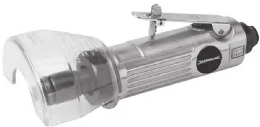
Air Cut-Off Tool / 75mm
Thank you for purchasing this Silverline tool. This manual contains information necessary for safe and effective operation of this product. This product has unique features and, even if you are familiar with similar products, it is necessary to read this manual carefully to ensure you fully understand the instructions. Ensure all users of the tool read and fully understand this manual.
Description of Symbols
The rating plate on your tool may show symbols. These represent important information about the product or instructions on its use.

Wear hearing protection
Wear eye protection
Wear breathing protection
Wear head protection

Wear hand protection

Read instruction Manual

DO NOT use with compressed gas cylinders!

Conforms to relevant legislation and safety standards

Environmental Protection
Air tools must not be disposed of with household waste. Air tools may contain traces of tool oil and other lubricants and so must be recycled accordingly
Specification
Maximum operating pressure: 6.3bar (90psi)
Air consumption: 170L/min (6cfm)
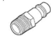
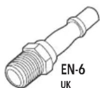
Air inlet: 14" BSP, supplied with two male airline quick connectors
EN-6 'UK' and EQ-4 European' types)
Minimum hose diameter: 9.5mm (3 / 8)
No load speed: 20,000min
Disc dimensions: 75 x 10 x 2mm (3" discs)
Angle: 0
Spindle thread: M6 (female)
Weight. 0.77kg
Noise and vibration information:
Level of sound pressure according to Machinery directive 2006/42/EC
Sound pressure: LPA = 84dB(A)
Sound power: LWA = 95dB(A)
Uncertainty: K = 3dB
The sound intensity level for the operator may exceed 85dB(A) and sound protection measures are necessary.
Vibration total values (triax vector sum) according to Machinery directive 2006/42/EC:
Vibration emission value: ah = 1.68m / s^2
Uncertainty: K = 1.5m / s^2
As part of our ongoing product development, specifications of Silverline products may alter without notice.
Noise and Vibration
Sound and vibration levels in the specification are determined according to ISO 28927-3. The figures given can be used to compare similar tools tested to this standard. These figures may be used to assess exposure to noise and vibration levels.
The figures represent normal use for the tool in normal working condition. A poorly maintained, incorrectly assembled or misused tool may produce increased levels of noise and vibration. The total working period that you can operate this tool must factor in periods where the tool is idle or switched off. Allow frequent rest breaks when operating this tool.
- It is in the interest of users to maximise their safety using the correct safety equipment, like ear defenders that protect against loud or repetitive noise, and anti-vibration gloves that minimise vibration. Do not operate the tool with your hands below a normal comfortable temperature, as vibration will have a greater effect.
Sound
- The noise directive was introduced to protect against the risk to health and safety arising or likely to arise from exposure to noise and risk of hearing. The Directive can be used to define noise exposure and the physical parameters, such as peak sound pressure and daily and weekly exposure level. Particular attention should be taken to exposure level and duration.
For more information on the Noise Directives 2003/10/EC and 2000/14/EC, please visit The European Agency for Safety and Health at work
www.osha.europa.eu.
Vibration
The European Physical Agents (Vibration) Directive 2002/44/EC was introduced to control the exposure of vibration at work. The Directive enables users of tools to make informed decisions on the amount of time spent working. Those who regularly operate high vibration equipment over a sustained period of time are at a higher risk of health problems. ISO 28927-3 measures vibration in three directions which is known as tri-axial or vector sum measurement. When operating high vibration equipment, ensure not to exceed exposure levels. For more details on The Vibration Directive 2002/44/EC please visit The European Agency for Safety and Health at work www.osha.europa.eu
General SafetyWarnings
- For multiple hazards, read and understand the safety instructions before installing, operating, repairing, maintaining, changing accessories on, or working near this tool. Failure to do so can result in serious bodily injury
- Only qualified and trained operators should install, adjust, or use this tool
- Do not modify this tool. Modifications can reduce the effectiveness of safety measures and increase the risks to the operator
- Do not discard the safety instructions; give them to the operator
- Do not use this tool if it has been damaged
- Tools shall be inspected periodically to verify that the ratings and markings required by this part of ISO 11148 are legibly marked on the tool. The employer/user should contact the manufacturer to obtain replacement marking labels when necessary
WARNING: This appliance is not intended for use by persons (including children) with reduced, physical or mental capabilities or lack of experience or knowledge unless they have been given supervision or instruction concerning use of the appliance by a person responsible for their safety. Children must be supervised to ensure that they do not play with the appliance.
Projectile Hazards
- Be aware that failure of the workpiece or accessories, or even of the inserted tool itself, can generate high-velocity projectiles
Always wear impact-resistant eye protection during operation of this tool. The grade of protection required should be assessed for each use
For overhead work, wear a safety helmet
The risks to others should also be assessed at this time - Ensure that the workpiece is securely fixed
- Entanglement Hazards
- Choking, scalping and/or lacerations can occur if loose clothing, personal jewellery, neck wear, hair or gloves are not kept away from the tool and its accessories
Operating Hazards
- Use of the tool can expose the operator's hands to hazards, including cuts, abrasions and heat
- Wear suitable gloves to protect hands
- Operators and maintenance personnel should be physically able to handle the bulk, weight and power of the tool
- Hold the tool correctly; be ready to counteract normal or sudden movements and have both hands available
- Maintain a balanced body position and secure footing
- Release the start-and-stop device in the case of an interruption of the energy supply
-
Use only lubricants recommended by the manufacturer
-
Personal protective safety glasses should be used; suitable gloves and protective clothing are recommended
- Inspect the cutting disc before each use. Do not use if cracked or broken or if it has been dropped
- Avoid direct contact with moving parts in order to prevent pinching or cutting of hands or other body parts.
- Wear suitable gloves to protect hands
- Never switch the tool on or off while the disc is in contact with the workpiece
- There is a risk of electrostatic discharge if used on plastic and other non-conductive materials
- Potentially explosive atmospheres can be caused by dust and fumes resulting from cutting or grinding
- Always use dust extraction or suppression systems which are suitable for the material being processed
Repetitive Motions Hazards
- When using this tool to perform work-related activities, the operator can experience discomfort in the hands, arms, shoulders, neck or other parts of the body
- While using this tool, the operator should adopt a comfortable posture whilst maintaining secure footing and avoiding awkward or off-balance postures. The operator should change posture during extended tasks; this can help avoid discomfort and fatigue
- If the operator experiences symptoms such as persistent or recurring discomfort, pain, throbbing, aching, tingling, numbness, burning sensations or stiffness, these warning signs should not be ignored. The operator should inform the employer and consult a qualified health professional
Accessory Hazards
- Disconnect the tool from the energy supply before fitting or changing the inserted tool or accessory
- Avoid direct contact with the inserted tool during and after use, as it can be hot or sharp
- Use only sizes and types of accessories and consumables that are recommended by the manufacturer of this tool; do not use other types or sizes of accessories or consumables
Grinding discs should not be used - Check that the maximum operating speed of the cutting disc is higher than the rated speed of the tool
Workplace Hazards
- Slips, trips and falls are major causes of workplace injury. Be aware of slippery surfaces caused by use of the tool and also of trip hazards caused by the air line or hydraulic hose
- This tool is not intended for use in potentially explosive atmospheres and is not insulated against contact with electric power
- Ensure that there are no electrical cables, gas pipes, etc., which can cause a hazard if damaged by use of the tool
Dust and Fume Hazards
- Dust and fumes generated when using this tool can cause ill health (for example cancer, birth defects, asthma and/or dermatitis); risk assessment and implementation of appropriate controls for these hazards are essential
- Risk assessment should include dust created by the use of the tool and the potential for disturbing existing dust
- Operate and maintain this tool as recommended in these instructions, to minimise dust or fume emissions
- Direct the exhaust so as to minimise disturbance of dust in a dust-filled environment
- Where dust or fumes are created, the priority should be to control them at the point of emission
- All integral features or accessories for the collection, extraction or suppression of airborne dust or fumes should be correctly used and maintained in accordance with the manufacturer's instructions
- Select, maintain and replace the consumable/inserted tool as recommended in the instruction handbook, to prevent an unnecessary increase in dust or fumes
- Use respiratory protection in accordance with employer's instructions and as required by occupational health and safety regulations
Noise Hazards
- Exposure to high noise levels can cause permanent, disabling hearing loss and other problems, such as tinnitus (ringing, buzzing, whistling or humming in the ears). Therefore, risk assessment and implementation of appropriate controls for these hazards are essential
- Appropriate controls to reduce the risk can include actions such as damping materials to prevent workpieces from 'ringing'
- Use hearing protection in accordance with employer's instructions and as required by occupational health and safety regulations
- Operate and maintain this tool as recommended in the instruction handbook, to prevent an unnecessary increase in the noise level
- Select, maintain and replace the consumable/inserted tool as recommended in the instruction handbook, to prevent an unnecessary increase in noise
- If the tool has a silencer, always ensure it is in place and in good working order when the tool is being operated
Vibration Hazards
- This information shall draw attention to vibration hazards that have not been eliminated by design and construction and remain as residual vibration risks. It shall enable employers to identify the circumstances in which the operator is likely to be at risk from vibration exposure If the vibration-emission value obtained using ISO 28927-3 does not adequately represent the vibration emission in the intended uses (and foreseeable misuses) of the machine, additional information and/or warnings shall be supplied to enable the risks arising from vibration to be assessed and managed.
- Exposure to vibration can cause disabling damage to the nerves and blood supply of the hands and arms
- Wear warm clothing when working in cold conditions and keep your hands warm and dry
- If you experience numbness, tingling, pain or whitening of the skin in your fingers or hands, stop using the sander or polisher, inform your employer and consult a physician
- Operate and maintain the sander or polisher as recommended in the instruction handbook, to prevent an unnecessary increase in vibration levels
- Hold the tool with a light but safe grip, taking account of the required hand reaction forces, because the risk from vibration is generally greater when the grip force is higher
Additional Safety Instructions for Pneumatic Power Tools
Air under pressure can cause severe injury:
Always shut off air supply, drain hose of air pressure and disconnect tool from air supply when not in use, before changing accessories or when making repairs
- Never direct air at yourself or anyone else
- Whipping hoses can cause severe injury. Always check for damaged or loose hoses and fittings
- Whenever universal twist couplings (claw couplings) are used, lock pins should be installed and whipcheck safety cables should be used to safeguard against possible hose-to-tool or hose-to-hose connection failure
- Do not exceed the maximum air pressure stated on the tool
- Never carry an air tool by the hose
Air Cut-Off Tool Safety
a) This power tool is intended to function as a cut-off tool. Read all safety warnings, instructions, illustrations and specifications provided with the power tool. Failure to follow all instructions listed below may result in serious injury.
b) Operations such as grinding, sanding, wire brushing or polishing are not recommended to be performed with this power tool. Operations for which the power tool was not designed may create a hazard and cause personal injury.
c) Do not use accessories which are not specifically designed and recommended by the tool manufacturer. Just because the accessory can be attached to your power tool it does not assure safe operation. Never use spacers or bushings to make an incorrectly-sized accessory fit the tool.
d) The rated speed of the accessory must be at least equal to the maximum speed marked on the power tool. Accessories running faster than their rated speed can break and fly apart.
e) The outside diameter and the thickness of your accessory must be within the capacity rating of your power tool. Incorrectly sized accessories cannot be adequately guarded or controlled.
f) The arbour size of wheels, flanges, backing pads or any other accessory must properly fit on the spindle of your power tool. Accessories with arbour holes that do not match the mounting hardware of the power tool will run out of balance, vibrate excessively and may cause loss of control.
g) Do not use a damaged accessory. Before each use inspect the accessory such as abrasive wheels for chips and cracks, backing pad for cracks, tear or excess wear. If power tool or accessory is dropped, inspect for damage or install an undamaged accessory. After inspecting and installing an accessory, position yourself and bystanders away from the plane of the rotating accessory and run the power tool at maximum no-load speed for one minute. Damaged accessories will normally break apart during this test time.
h) Wear personal protective equipment. Depending on application, use face shield, safety goggles or safety glasses. As appropriate, wear dust mask, hearing protectors, gloves and workshop apron capable of stopping small abrasive or workpiece
fragments. Eye protection must be capable of stopping flying debris generated by various operations. The dust mask or respirator must be capable of filtrating particles generated by your operation. Prolonged exposure to high intensity noise may cause hearing loss.
i) Keep bystanders a safe distance away from the work area. Anyone entering the work area must wear personal protective equipment. Fragments of workpiece or of a broken accessory may fly away and cause injury beyond immediate area of operation.
j) Hold the power tool by insulated gripping surfaces only, when performing an operation where the cutting accessory may contact hidden wiring. Cutting accessory contacting a 'live' wire may make exposed metal parts of the power tool 'live' and could give the operator an electric shock.
k) Position the supply hose clear of the spinning accessory. If you lose control, the hose may be cut or snagged and your hand or arm may be pulled into the spinning accessory.
1) Never lay the power tool down until the accessory has come to a complete stop. The spinning accessory may grab the surface and pull the power tool out of your control.
m) Wheels must be used only for recommended applications. For example: do not grind with the side of the cut-off wheel. Abrasive cut-off wheels are intended for peripheral grinding; side forces applied to these wheels may cause them to shatter.
n) Always use undamaged wheel flanges that are of correct size and shape for your selected wheel. Proper wheel flanges support the wheel, thus reducing the possibility of wheel breakage. Flanges for cut-off wheels may be different from grinding wheel flanges.
a) Ensure the air supply pressure does not exceed the maximum operating pressure of the tool. Exceeding the pressure limit of the tool may cause erratic and unpredictable operation, leading to tool damage or serious injury.
p) The operator must ensure there are no bystanders within the vicinity. Bystanders are at risk of harm from flying debris and harmful gases produced from cutting operations.
q) Do not use the cut-off tool in a potentially explosive environment. Working with certain materials that produce a large concentration of dust can make the environment potentially explosive. Always ensure a sufficient dust extraction system is present when in use.
r) In the event the energy supply is interrupted, release the start/stop mechanism, and any switch locking device. This will prevent unintentional tool start-up if energy supply is reconnected.
s) Always use blotters during disc installation (if provided by the manufacturer). Blotters are specifically designed to dampen forces exerted between the spindle and disc. Failure to use, or improper use of, the provided blotters will promote premature or abrupt failure of the accessory.
t) Keep the cutting guard in place and in good condition at all times. Inspect the condition of the cutting guard regularly, ensuring it is correctly installed and in good condition. If the guard shows prominent defects, discard and replace.
Note: Internal grinding may not require a guard, providing the workpiece encloses the abrasive accessory.
Before use, inspect the condition and installation of the spindle and gas supply connecting components. Do not use the tool if the spindle or gas supply connection points show signs of damage or fatigue.
Additional SafetyWarnings Specific for Abrasive Cutting-Off Operations
a) Do not 'jam' the cut-off wheel or apply excessive pressure. Do not attempt to make an excessive depth of cut. Overstressing the wheel increases the loading and susceptibility to twisting or binding of the wheel in the cut, and also the possibility of kickback or wheel breakage.
b) When the wheel is binding or when interrupting a cut for any reason, shut off the power tool and hold the power tool motionless until the wheel comes to a complete stop. Never attempt to remove the cut-off wheel from the cut while the wheel is in motion otherwise kickback may occur. Investigate and take corrective action to eliminate the cause of wheel binding.
c) Do not restart the cutting operation in the workpiece. Check the cutting accessory for damage and allow the wheel to reach full speed before carefully re-entering the cut. The wheel may bind, walk up or kickback if the power tool is restarted in the workpiece.
d) Support panels or any oversized workpiece to minimise the risk of wheel pinching and kickback. Large workpieces tend to sag under their own weight. Supports must be placed under the workpiece near the line of cut and near the edge of the workpiece on both sides of the wheel
e) Use extra caution when making a 'pocket cut' into existing walls or other blind areas. The protruding wheel may cut gas or water pipes, electrical wiring or objects that can cause kickback.
Product Familiarisation
1 Body/Handle
2 Guard
3 Spindle
4 Bplit & Washer
5 Cutting Disc (not supplied)
65mm Hex Key
7 14mm Spanner
8 Safety Catch
9 Speed Control
10 Quick Connector
Intended Use
- Rotating cut off tool, powered by compressed air from a compressor, for cutting of metal (mainly thin sheet metal, nuts/bolts, car bodywork etc.).
Unpacking Your Tool
- Carefully unpack and inspect your tool. Fully familiarise yourself with all its features and functions
- Ensure that all parts of the tool are present and in good condition. If any parts are missing or damaged, have such parts replaced before attempting to use this tool
Before Use
Fitting the quick connector
Note: This tool is supplied with two different male airline quick connectors:
EQ-4 commonly used in Europe
EN-6 - mainly used in the UK
EQ-4 Europe
-
Please choose the connector that is compatible with the airline system you are using, and install as outlined below:
-
Apply some PTFE tape (not included) to the screw threads of the Quick Connector (10). This will help to maintain an air tight seal
Note: Apply PTFE tape tightly and in a clockwise direction, so it does not come off when the thread is screwed into the tool.
- Remove the protective plug from the air inlet
- Using a spanner (not included) screw the quick connector into the air inlet located at the base of the handle
- Connect to airline, pressurise carefully and carry out a leak check (e.g. by spraying small amounts of soapy water on to the outside of the connectors)
Air lines fitted with matching female quick connectors will now be a push fit to the tool
Air supply connection
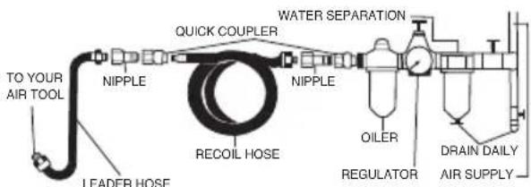
This tool should be connected to a clean, dry air supply with inline oiler and water separator
- Do not allow supply pressure to exceed the maximum stated (see "Specifications")
- Ensure that water is drained from air system daily
- Ensure that all parts of the system (hoses, couplers, etc.) are correctly rated for the air pressure to be used
Setting tool power
- The maximum tool speed/power can be adjusted by reducing/increasing the air supply pressure within the range specified in 'Specifications'
- Whilst working with the tool, speed adjustments can be made via the Speed Control Trigger (9)
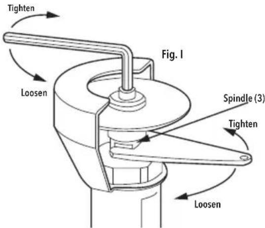
Fitting a cutting disc
WARNING: Always disconnect the tool from the air supply before fitting or removing a cutting disc.
- Slot the Spanner (7) over the Spindle (3) so that it grips the two flat faces (see Fig. 1). The spindle should be held securely and not able to rotate
- Use the Hex Key (6) to unscrew the Bolt & Flange (4)
- Remove the disc if in place
- Fit a new disc of correct size (see 'Specifications'), following the manufacturer's guidance for direction of rotation
Note: Unless otherwise stated, the metal ring at the centre of the disc should face the Spindle (3).
- Refit the Bolt & Flange(4) in the correct orientation (Image A), ensuring it is not deformed, burred or notched, and tighten using the spanner and hex key
WARNING: A damaged flange may cause irregular pressure on the disc, and may cause it to break.
WARNING: DO NOT overtighten. The direction of rotation will prevent the bolt from becoming loose.
- Spin the Cutting Disc (5) by hand to check it is secure and correctly aligned
Adjusting the guard
Note: Inspect the guard before every use, and replace if damaged.
WARNING: This tool must NEVER be operated without the guard in place and correctly positioned.
- Depending in the application and work angle, the position f the guard must be adjusted, to always be located between the disc and the user:
- Use the Hex Key (6) to loosen the guard clamping screw
- Adjust guard position and re-tighten screw
WARNING: DO NOT overtighten. Overtightening may damage the guard.
Operation
WARNING: DO NOT switch the machine on/off when the disc is in contact with the workpiece. Always allow the motor to reach its full speed before applying load, and to stop completely before placing the grinder down. Always hold the machine securely, using both hands, on the handles provided.
Note: Do not apply too much pressure to the machine whilst grinding. Excessive pressure does not result in more effective removal of material, but will cause premature wear of the grinding disc and increase wear and tear on the machine.
WARNING: This is a cutting device only. DO NOT attempt to use it for sideways grinding, as axial force will cause the cutting disc to shatter.
- Hold the tool by its Handle (1) and turn it so the open side of the Guard (2) is facing away from you. Your thumb should wrap around the Handle (1) and your fingers should sit on the Speed Control Trigger (9).
- Disengage the Safety Catch (8) and gently squeeze the trigger towards the handle
- The Cutting Disc (5) will begin to spin. Squeeze the trigger further to increase the speed, slightly release to decrease the speed
- With the disc spinning at the required speed, slowly move the disc towards the workpiece to be cut and gently engage the material
WARNING: When the disc begins to cut, it will force the tool to move sideways. Make sure you have a firm grip on the tool and are ready to counteract this.
- As the disc begins to cut, take note of the direction of the waste material being ejected. It should be going away from you, and not towards any person or object to which it may cause damage
- To stop the tool, remove the disc from the workpiece, fully release the trigger and allow the safety catch to re-engage
Note: DO NOT allow the tool to run in 'idle rotation' for an extended period of time. This will shorten its life.
WARNING: Be aware that air tools may hold residual pressure after use. Always bleed air pressure from the tool after shutting off air supply.
Accessories
- Accessories for this tool including Face Masks and Safety Goggles is available from your Silverline stockist. Spare parts can be obtained from your Silverline dealer or www. toolsparesonline.com
Maintenance
WARNING: Always disconnect from the air supply and depressurise before cleaning or carrying out any maintenance.
Cleaning
- Keep your tool clean at all times. Dirt and dust will cause internal parts to wear quickly, and shorten the machine's service life. Clean the body of your machine with a soft brush, or dry cloth
IMPORTANT: There is very little that can go wrong with your air tool and it should be noted that when an air tool fails to work it is generally because the internal workings have corroded due to dirty, wet air and failure to follow the instructions given below.
Daily maintenance procedure: Disconnect from the air supply, pour the equivalent of a tablespoon of oil into the air intake. Operate the machine at low speed to thoroughly lubricate all internal workings.
- If the machine is in constant use or used for long periods at a time, a combined filter/ lubricator must be fitted. There must be an air filter fitted at all times
- Use air tool oil only. DO NOT UNDER ANY CIRCUMSTANCES USE NORMAL ENGINE OIL
- Failure to comply with the operating and maintenance instructions may invalidate the guarantee
Storage
- Store this tool carefully in a secure, dry place out of the reach of children
Disposal
- As with other power tools, air tools should not be disposed of with household waste
Air tools may contain traces of tool oil and other lubricants and so must be recycled accordingly - Contact your local waste disposal authority for information on the correct way to dispose of power tools
Troubleshooting
| Problem Possible Cause Solution | ||
| Tool operating slowly | Pressure incorrect Set the correct air pressure according to the specified | |
| Dirt within the mechanism Pour oil into air inlet as per maintennce instructions | ||
| Air blockage Operate tool in short bursts to clear blockage | ||
| Air leak | Check all fittings and hose for air leaks and correct issue by re-tightening, using PTFE tape or replacing | |
| Blockage in gauze mesh filter Remove Quick Connector (10) and clean mesh filter | ||
| Tool seized | Dirt or rust in mechanism Try 'Tool operating slowly' solutions | |
| Dirt or rust in mechanism Tap tool gently with a soft mallet | ||
| Dirt or rust in mechanism | Free mechanism by rotating drive manually when disconnected from air line | |
| Strong vibrations when tool is switched on | Cutting disc fitted incorrectly Remove disc, inspect for damage and refit | |
| Cutting disc damaged (cracks, deformations or splinters) Replace cutting disc | ||
| Flange damaged (burred or notched) Replace flange | ||
| Spindle bent Have the tool repaired by an authorised Silverline service centre | ||
| Tool will not stop after trigger is fully released | Throttle valve O-ring or valve seat damaged Have the tool repaired at an authorised Silverline service centre | |
| If the above troubleshooting solutions fail, contact your dealer or an authorised Silverline service centre. | ||
Silverline Tools Guarantee
This Silverline product comes with a 3 year guarantee
Register this product at www.silverinetools.com within 30 days of purchase in order to qualify for the 3 year guarantee. Guarantee period begins according to the date of purchase on your sales receipt.
Registering your purchase
Registration is made at silverlinetools.com by selecting the Guarantee Registration button. You will need to enter:
- Your personal details
Details of the product and purchase information
Once this information is entered your guarantee certificate will be created in PDF format for you to print out and keep with your purchase.
Terms & Conditions
Guarantee period becomes effective from the date of retail purchase as detailed on your sales receipt.
PLEASE KEEP YOUR SALES RECEIPT
If this product develops a fault within 30 days of purchase, return it to the stockist where it was purchased, with your receipt, stating details of the fault. You will receive a replacement or refund.
If this product develops a fault after the 30 day period, return it to:
Silverline Tools Service Centre
PO Box 2988
Yeovil
BA21 1WU, UK
The guarantee claim must be submitted during the guarantee period.
You must provide the original sales receipt indicating the purchase date, your name, address and place of purchase before any work can be carried out.
You must provide precise details of the fault requiring correction.
Claims made within the guarantee period will be verified by Silverline Tools to establish if the deficiencies are related to material or manufacturing of the product.
Carriage will not be refunded. Items for return must be in a suitably clean and safe state for repair, and should be packaged carefully to prevent damage or injury during transportation. We may reject unsuitable or unsafe deliveries.
All work will be carried out by Silverline Tools or its authorized repair agents.
The repair or replacement of the product will not extend the period of guarantee
Defects recognised by us as being covered by the guarantee shall be corrected by means of repair of the tool, free of charge (excluding carriage charges) or by replacement with a tool in perfect working order.
Retained tools, or parts, for which a replacement has been issued, will become the property of Silverline Tools.
The repair or replacement of your product under guarantee provides benefits which are additional to and do not affect your statutory rights as a consumer.
What is covered:
The repair of the product, if it can be verified to the satisfaction of Silverline Tools that the deficiencies were due to faulty materials or workmanship within the guarantee period.
If any part is no longer available or out of manufacture, Silverline Tools will replace it with a functional replacement part.
Use of this product in the EU.
What is not covered:
Silverline Tools does not guarantee repairs required as a result of:
Normal wear and tear caused by use in accordance with the operating instructions eg blades, brushes, belts, bulbs, batteries etc.
The replacement of any provided accessories drill bits, blades, sanding sheets, cutting discs and other related items.
Accidental damage, faults caused by negligent use or care, misuse, neglect, careless operation or handling of the product.
Use of the product for anything other than normal domestic purposes.
Change or modification of the product in any way.
Use of parts and accessories which are not genuine Silverline Tools components.
Faulty installation (except installed by Silverline Tools).
Repairs or alterations carried out by parties other than Silverline Tools or its authorized repair agents.
Claims other than the right to correction of faults on the tool named in these guarantee conditions are not covered by the guarantee.
CE Declaration of Conformity
The undersigned: Mr Darrell Morris
as authorised by: Silverline
Declarethat:This declaration has been issued under the sole responsibility of the manufacturer.
The object of the declaration is in conformity with the relevant Union harmonisation Legislation.
Identification code: 598446
Description: Air Cut-Off Tool
Conforms to the following directives and standards:
- Machinery Directive 2006/42/EC
EN792-7:2001+A1:2008
Notified body: Intertek
The technical documentation is kept by: Silverline
Date:23.04.2015
Signed:

Managing Director
Name and address of the manufacturer:
Powerbox International Limited, Company No. 06897059. Registered address: Powerbox, Boundary
Way, Lufton Trading Estate, Yeovil, Somerset BA22 8HZ, United Kingdom.
Introduction
Silverline Tools Service Centre
PO Box 2988
Yeovil
BA21 1WU, GroBbritannien
I've protection ocular.
The protection respiratoria.
Characteristicas techniques
Silverline Tools Service Centre
PO Box 2988
Yeovil
BA21 1WU,GB
Silverline Tools Service Centre
PO Box 2988
Yeovil
BA21 1WU, GB
Silverline Tools Service Centre
PO Box 2988
Yeovil
BA21 1WU, UK
Powerbox International Limited, Company No. 06897059. Registered address: Powerbox, Boundary Way, Lufton Trading Estate, Yeovil, Somerset BA22 8HZ, United Kingdom.