M8100KX2 - Drill MAKITA - Free user manual and instructions
Find the device manual for free M8100KX2 MAKITA in PDF.
Download the instructions for your Drill in PDF format for free! Find your manual M8100KX2 - MAKITA and take your electronic device back in hand. On this page are published all the documents necessary for the use of your device. M8100KX2 by MAKITA.
USER MANUAL M8100KX2 MAKITA
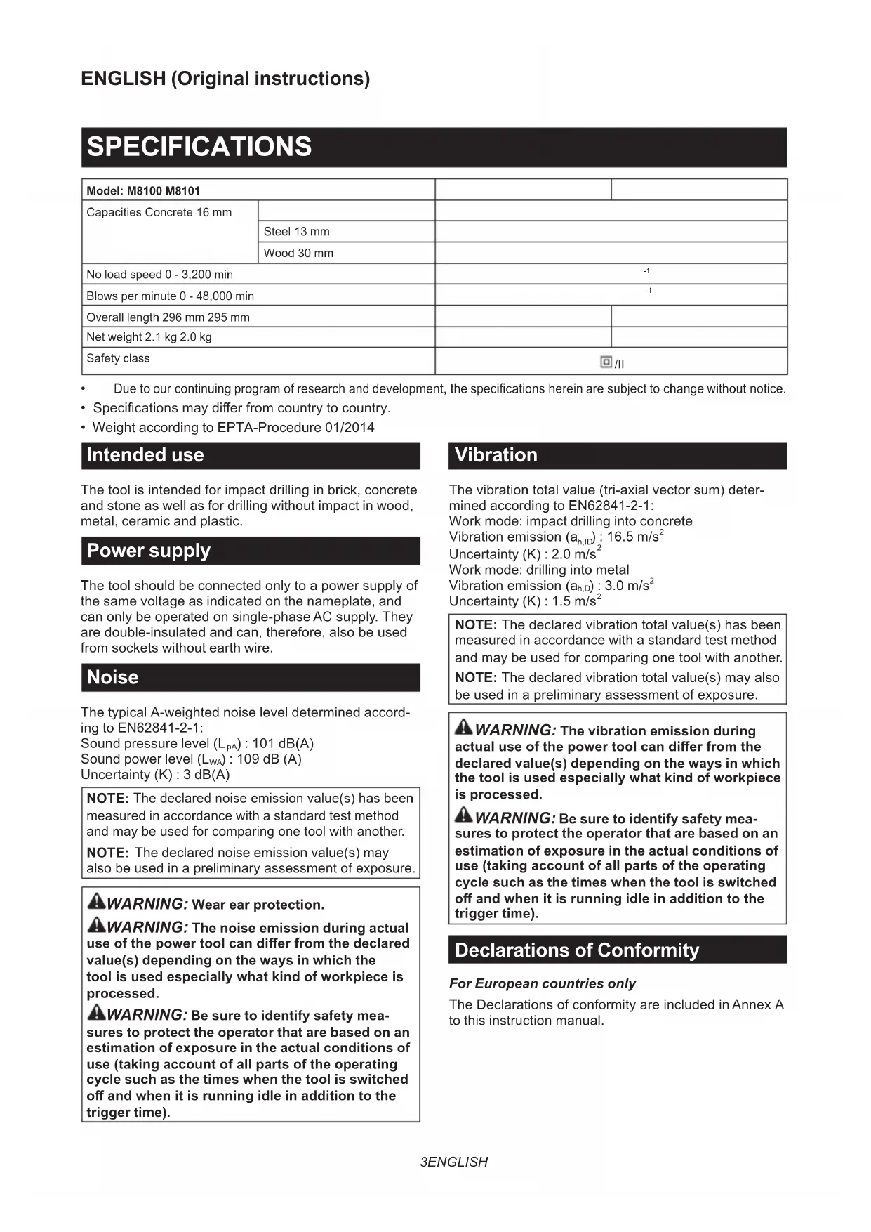
Due to our continuing program of research and development, the specications herein are subject to change without notice.
- Specications may dier from country to country.
- Weight according to EPTA-Procedure 01/2014 Intended use The tool is intended for impact drilling in brick, concrete and stone as well as for drilling without impact in wood, metal, ceramic and plastic. Power supply The tool should be connected only to a power supply of the same voltage as indicated on the nameplate, and can only be operated on single-phase AC supply. They are double-insulated and can, therefore, also be used from sockets without earth wire. Noise The typical A-weighted noise level determined accord- ing to EN62841-2-1: Sound pressure level (L
) : 109 dB (A) Uncertainty (K) : 3 dB(A) NOTE: The declared noise emission value(s) has been measured in accordance with a standard test method and may be used for comparing one tool with another. NOTE: The declared noise emission value(s) may also be used in a preliminary assessment of exposure.
WARNING: Wear ear protection.
WARNING: The noise emission during actual
use of the power tool can dier from the declared value(s) depending on the ways in which the tool is used especially what kind of workpiece is processed.
WARNING: Be sure to identify safety mea-
sures to protect the operator that are based on an estimation of exposure in the actual conditions of use (taking account of all parts of the operating cycle such as the times when the tool is switched o and when it is running idle in addition to the trigger time). Vibration The vibration total value (tri-axial vector sum) deter- mined according to EN62841-2-1: Work mode: impact drilling into concrete Vibration emission (a h,ID ) : 16.5 m/s
Work mode: drilling into metal Vibration emission (a h,D ) : 3.0 m/s
NOTE: The declared vibration total value(s) has been measured in accordance with a standard test method and may be used for comparing one tool with another. NOTE: The declared vibration total value(s) may also be used in a preliminary assessment of exposure.
WARNING: The vibration emission during
actual use of the power tool can dier from the declared value(s) depending on the ways in which the tool is used especially what kind of workpiece is processed.
WARNING: Be sure to identify safety mea-
sures to protect the operator that are based on an estimation of exposure in the actual conditions of use (taking account of all parts of the operating cycle such as the times when the tool is switched o and when it is running idle in addition to the trigger time). Declarations of Conformity For European countries only The Declarations of conformity are included in Annex A to this instruction manual.4 ENGLISH General power tool safety warnings
Read all safety warnings, instruc- tions, illustrations and specications provided with this power tool. Failure to follow all instructions listed below may result in electric shock, re and/or serious injury. Save all warnings and instruc- tions for future reference. The term "power tool" in the warnings refers to your mains-operated (corded) power tool or battery-operated (cordless) power tool. Hammer drill safety warnings Safety instructions for all operations
1. Wear ear protectors when impact drilling.
Exposure to noise can cause hearing loss.
2. Use the auxiliary handle(s). Loss of control can
cause personal injury.
Hold the power tool by insulated gripping sur- faces, when performing an operation where the cutting accessory may contact hidden wiring or its own cord. Cutting accessory contacting a "live" wire may make exposed metal parts of the power tool "live" and could give the operator an electric shock.
Always be sure you have a rm footing. Be sure no one is below when using the tool in high locations.
5. Hold the tool rmly with both hands.
6. Keep hands away from rotating parts.
7. Do not leave the tool running. Operate the tool
only when hand-held.
8. Do not touch the drill bit or the workpiece
immediately after operation; they may be extremely hot and could burn your skin.
Some material contains chemicals which may be toxic. Take caution to prevent dust inhalation and skin contact. Follow material supplier safety data.
10. If the drill bit cannot be loosened even you
open the jaws, use pliers to pull it out. In such a case, pulling out the drill bit by hand may result in injury by its sharp edge. Safety instructions when using long drill bits
Never operate at higher speed than the maximum speed rating of the drill bit. At higher speeds, the bit is likely to bend if allowed to rotate freely without contacting the workpiece, resulting in personal injury.
Always start drilling at low speed and with the bit tip in contact with the workpiece. At higher speeds, the bit is likely to bend if allowed to rotate freely without contacting the workpiece, resulting in personal injury.
Apply pressure only in direct line with the bit and do not apply excessive pressure. Bits can bend causing breakage or loss of control, resulting in personal injury. SAVE THESE INSTRUCTIONS.
WARNING: DO NOT let comfort or familiarity
with product (gained from repeated use) replace strict adherence to safety rules for the subject product. MISUSE or failure to follow the safety rules stated in this instruction manual may cause serious personal injury. FUNCTIONAL DESCRIPTION CAUTION: Always be sure that the tool is switched o and unplugged before adjusting or checking function on the tool. Switch action
WARNING: Before plugging in the tool,
always check to see that the switch trigger actu- ates properly and returns to the "OFF" position when released. ► Fig.1: 1. Switch trigger 2. Lock button To start the tool, simply pull the switch trigger. Tool speed is increased by increasing pressure on the switch trigger. Release the switch trigger to stop. For continuous operation, pull the switch trigger, push in the lock button and then release the switch trigger. To stop the tool from the locked position, pull the switch trigger fully, then release it. CAUTION: Switch can be locked in “ON” posi- tion for ease of operator comfort during extended use. Apply caution when locking tool in “ON” position and maintain rm grasp on tool. Reversing switch action CAUTION: Always check the direction of rotation before operation. CAUTION: Use the reversing switch only after the tool comes to a complete stop. Changing the direction of rotation before the tool stops may dam- age the tool. ► Fig.2: 1. Reversing switch lever This tool has a reversing switch to change the direc- tion of rotation. Move the reversing switch lever to the position (A side) for clockwise rotation or to the posi- tion (B side) for counterclockwise rotation. Selecting the action mode CAUTION: Always slide the action mode changing lever all the way to your desired mode position. If you operate the tool with the lever posi- tioned halfway between the mode symbols, the tool may be damaged. ► Fig.3: 1. Action mode changing lever This tool has an action mode changing lever. For rota- tion with hammering, slide the action mode changing lever to the right ( symbol). For rotation only, slide the action mode changing lever to the left ( symbol).5 ENGLISH ASSEMBLY Installing side grip (auxiliary handle) CAUTION: Always be sure that the tool is switched o and unplugged before installing or removing the side grip. ► Fig.4: 1. Grip base 2. Teeth 3. Side grip (auxiliary handle) 4. Protrusion 5. Loosen 6. Tighten Always use the side grip to ensure operating safety. Install the side grip so that the teeth on the grip t in between the protrusions on the tool barrel. Then tighten the grip by turning clockwise at the desired position. It may be swung 360° so as to be secured at any position. Installing or removing drill bit CAUTION: Always be sure that the tool is switched o and unplugged before installing or removing the drill bit. For model M8100 ► Fig.5: 1. Drill chuck 2. Chuck key To install the drill bit, place it in the drill chuck as far as it will go. Tighten the chuck by hand. Place the chuck key in each of the three holes and tighten clockwise. Be sure to tighten all three chuck holes evenly. To remove the drill bit, turn the drill chuck key counter- clockwise in just one hole, then loosen the chuck by hand. After using the chuck key, be sure to return it to the original position. For model M8101 ► Fig.6: 1. Sleeve 2. Ring Hold the ring and turn the sleeve counterclockwise to open the chuck jaws. Place the drill bit in the drill chuck as far as it will go. Hold the ring rmly and turn the sleeve clockwise to tighten the chuck. To remove the drill bit, hold the ring and turn the sleeve counterclockwise. Depth gauge ► Fig.7: 1. Side grip 2. Depth gauge 3. Grip base The depth gauge is convenient for drilling holes of uniform depth. Loosen the side grip and insert the depth gauge into the hole in the grip base. Adjust the depth gauge to the desired depth and tighten the side grip rmly. NOTE: The depth gauge cannot be used at the posi- tion where the depth gauge strikes against the gear housing. OPERATION CAUTION: Always use the side grip (auxiliary handle) and rmly hold the tool by both side grip and switch handle during operations. ► Fig.8 Hammer drilling operation CAUTION: There is tremendous and sudden twisting force exerted on the tool/drill bit at the time of hole break- through, when the hole becomes clogged with chips and particles, or when striking reinforcing rods embedded in the concrete. Always use the side grip (auxiliary handle) and rmly hold the tool by both side grip and switch handle during operations. Failure to do so may result in the loss of control of the tool and potentially severe injury. When drilling in concrete, granite, tile, etc., slide the action mode changing lever to the position of symbol to use "rota- tion with hammering" action. Be sure to use a tungsten-car- bide tipped drill bit. Do not apply more pressure when the hole becomes clogged with chips or particles. Instead, run the tool at an idle, then remove the drill bit partially from the hole. By repeating this several times, the hole will be cleaned out. After drilling the hole, use the blow-out bulb to clean the dust out of the hole. Drilling operation CAUTION: Pressing excessively on the tool will not speed up the drilling. In fact, this excessive pressure will only serve to damage the tip of your drill bit, decrease the tool performance and shorten the service life of the tool. CAUTION: Hold the tool rmly and exert care when the drill bit begins to break through the workpiece. There is a tremendous force exerted on the tool/drill bit at the time of hole break through. CAUTION: A stuck drill bit can be removed simply by setting the reversing switch to reverse rotation in order to back out. However, the tool may back out abruptly if you do not hold it rmly. CAUTION: Always secure workpieces in a vise or similar hold-down device. When drilling in wood, metal or plastic materials, slide the action mode changing lever to the position of symbol to use "rotation only" action. Drilling in wood When drilling in wood, the best results are obtained with wood drills equipped with a guide screw. The guide screw makes drilling easier by pulling the drill bit into the workpiece. Drilling in metal To prevent the drill bit from slipping when starting a hole, make an indentation with a center-punch and hammer at the point to be drilled. Place the point of the drill bit in the indentation and start drilling. Use a cutting lubricant when drilling metals. The excep- tions are iron and brass which should be drilled dry.6 ENGLISH MAINTENANCE CAUTION: Always be sure that the tool is switched o and unplugged before attempting to perform inspection or maintenance. NOTICE: Never use gasoline, benzine, thinner, alcohol or the like. Discoloration, deformation or cracks may result. To maintain product SAFETY and RELIABILITY, repairs, carbon brush inspection and replacement, any other maintenance or adjustment should be performed by Makita Authorized or Factory Service Centers, always using Makita replacement parts.7 FRANÇAIS FRANÇAIS (Instructions originales) SPÉCIFICATIONS Modèle : M8100 M8101 Capacités Béton 16 mm Acier 13 mm Bois 30 mm Vitesse à vide 0 - 3 200 min
Incertezza (K): 2,0 m/s