MTX204 - Multimeter METRIX - Free user manual and instructions
Find the device manual for free MTX204 METRIX in PDF.
| Product Type | Digital Multimeter |
| Brand | Metrix |
| Model | MTX204 |
| Dimensions (with holster) | 170 × 80 × 50 mm |
| Weight (with batteries) | 320 g |
| Power Supply | 2 AA 1.5 V batteries (LR6) or Ni-MH rechargeable batteries |
| Battery Life | Approximately 500 hours (VLowZ/VAC without backlight) |
| Display | LCD with blue backlight and white flashlight |
| Measurements | AC/DC/AC+DC voltage, AC/DC/AC+DC current, resistance, continuity, diode test, capacitance, non-contact voltage detection (NCV), VLowZ, frequency, duty cycle |
| Measurement Ranges | Voltage: 60 mV to 1000 V DC, 750 V AC; Current: 600 µA to 10 A; Resistance: 600 Ω to 60 MΩ; Capacitance: 10 nF to 100 mF |
| Safety Category | CAT III 600 V |
| Protection Rating | IP54 |
| Operating Temperature | -20 °C to 55 °C |
| Storage Temperature | -40 °C to 60 °C |
| Humidity | Up to 90% RH at 45 °C |
| Maintenance and Cleaning | Disconnect, use a soft cloth and soapy water; avoid alcohol and solvents |
| Replacement Parts | Fuses: F1 630 mA/1000 V, F2 10 A/1000 V; AA batteries; test leads |
| Warranty | 24 months |
| Included Accessories | 2 AA batteries, 2 test leads (red/black) |
Frequently Asked Questions - MTX204 METRIX
User questions about MTX204 METRIX
0 question about this device. Answer the ones you know or ask your own.
Ask a new question about this device
Download the instructions for your Multimeter in PDF format for free! Find your manual MTX204 - METRIX and take your electronic device back in hand. On this page are published all the documents necessary for the use of your device. MTX204 by METRIX.
USER MANUAL MTX204 METRIX
TRMS AC, AC+DC DIGITAL MULTIMETER 6,000-COUNT
TRMS AC, AC+DC DIGITAL-MULTIMETER 6.000 PUNKTE
MULTIMETRO DIGITALE TRMS AC, AC+DC 6.000 PUNTI
MULTIMETRO DIGITALE TRMS CA, CA+CC 6.000 PUNTOS
DIGITALNI TRMS AC, AC+DC MULTIMETRY
DIGITALE MULTIMETER AC, AC+DC TRMS
CYFROWEMIERNIKIUNIWERSALNETRMS
MULTIMETRE DIGITALE TRMS
UNΦPOBbIe MYJbTUMETPbI JJIa
FR 1
GB 22
DE 42
IT 63
ES. 83
CZ 104
NL 125
PL 146
RO. 167
RU. 188
ANNEX 210
SOMMAIRE
- INSTRUCTIONS GENÉRALES 2
1.1. Precautions and safety measures 23
2. INSTRUMENT OVERVIEW 25
2.1. Delivery condition 25
2.2. Accessories and spares 25
2.3. Functions 25
2.4. Device description 26
2.5. Display 28
2.6. Fixation and stand 29
3. USE 30
3.1. Precautions for use 30
3.2. First use 30
3.3. Backlight and Torch light 31
3.4. Measuring AC, DC or AC+DC voltages 31
3.5. Measuring AC, DC or AC+DC current 32
3.6. Measuring continuity 33
3.7. Measuring resistance 33
3.8. Testing Diodes 33
3.9. Measuring capacitance 34
3.10. Non Contact Voltage Detection (NCV) 35
3.11. VlowZ 36
3.12. Other measurements 36
4. TECHNICAL SPECIFICATIONS 36
5. SPECIFICATIONS 39
6. MAINTENANCE 40
6.1. Cleaning 40
6.2. Testing the 10A Fuse 40
6.3. Replacement of the battery and fuse 41
7. WARRANTY 41
Thank you for purchasing a MTX 204. For best results from your instrument:
- read this user manual carefully,
- comply with the precautions for use.
1.1. Precautions and safety measures
This device is compliant with safety standard IEC 61010-2-033, the leads are compliant with IEC 61010-2-031, and the current sensors are compliant with IEC 61010-2-032, for voltages up to 600V in category IV or 1,000V in category III. Failure to observe the safety instructions may result in electric shock, fire, explosion, or destruction of the instrument and of the installations.
1.1.1. Symbols
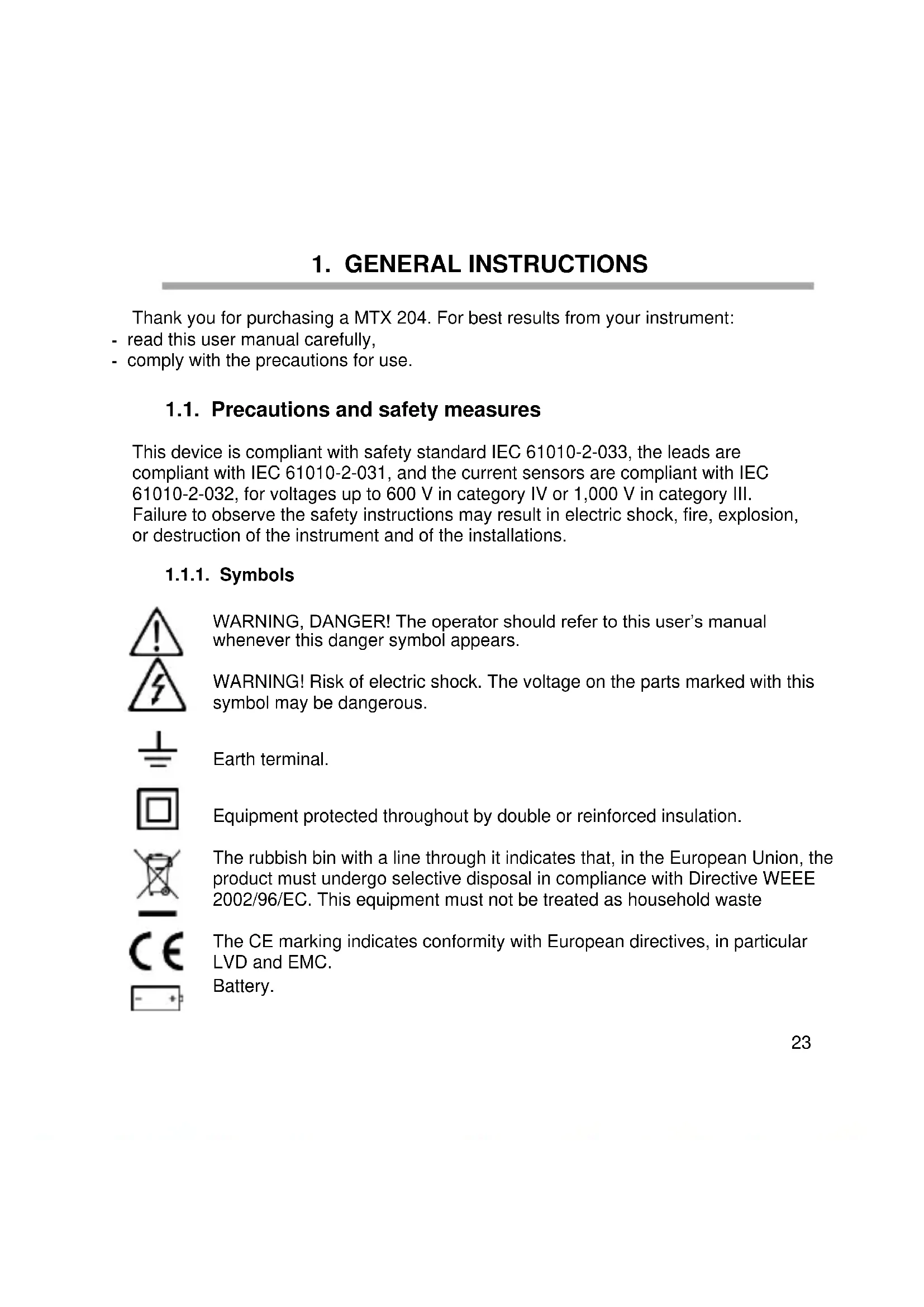
WARNING, DANGER! The operator should refer to this user's manual whenever this danger symbol appears.

WARNING! Risk of electric shock. The voltage on the parts marked with this symbol may be dangerous.

Earth terminal.
Equipment protected throughout by double or reinforced insulation.

The rubbish bin with a line through it indicates that, in the European Union, the product must undergo selective disposal in compliance with Directive WEEE 2002/96/EC. This equipment must not be treated as household waste

The CE marking indicates conformity with European directives, in particular LVD and EMC.
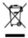
Battery.
Alternating current.
Direct current.
AC or DC
Fuse (FUSED)
Capacitor, capacitance
Diode
Resistance
Important instruction.
1.1.2. Definitions of the measurement categories
Measurement category II corresponds to measurements taken on circuits directly connected to low-voltage installations.
Example: power supply to domestic electrical appliances and portable tools.
Measurement category III corresponds to measurements on building installations. Example: distribution panel, circuit-breakers, machines or fixed industrial devices.
Measurement category IV corresponds to measurements taken at the source of low-voltage installations.
Example: power feeders, meters and protection devices.
2.1. Delivery condition
Check completeness of the delivery against your order.
- Multilingual user manual on paper
- a set of 2 batteries AA or LR6
Test lead elbowed 1,5 m red with probe tips
Test lead elbowed 1,5 m black with probe tips
2.2. Accessories and spares
Spares
Set of Test lead RD/BK with test probes-elbowed male banana plugs PVC Set of Test lead RD/BK with test probes-elbowed male banana plugs silicon
Accessories
Test probes cat III/IV
Crocodiles clips
For the accessories and spares, consult our web site:
www.chauvin-arnoux.com
2.3. Functions
The MTX 204 is an instrument for measuring electrical quantities that groups the following functions:
- AC, DC, or AC + DC voltage measurement,
- AC, DC or AC + DC current measurement,
- resistance measurement,
- continuity measurement with beeper,
- diode test,
- capacitance measurement,
- non-contact voltage detection
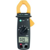
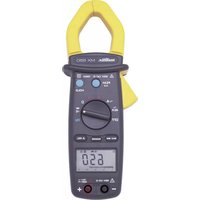
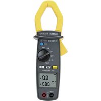
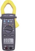
2.4. Device description
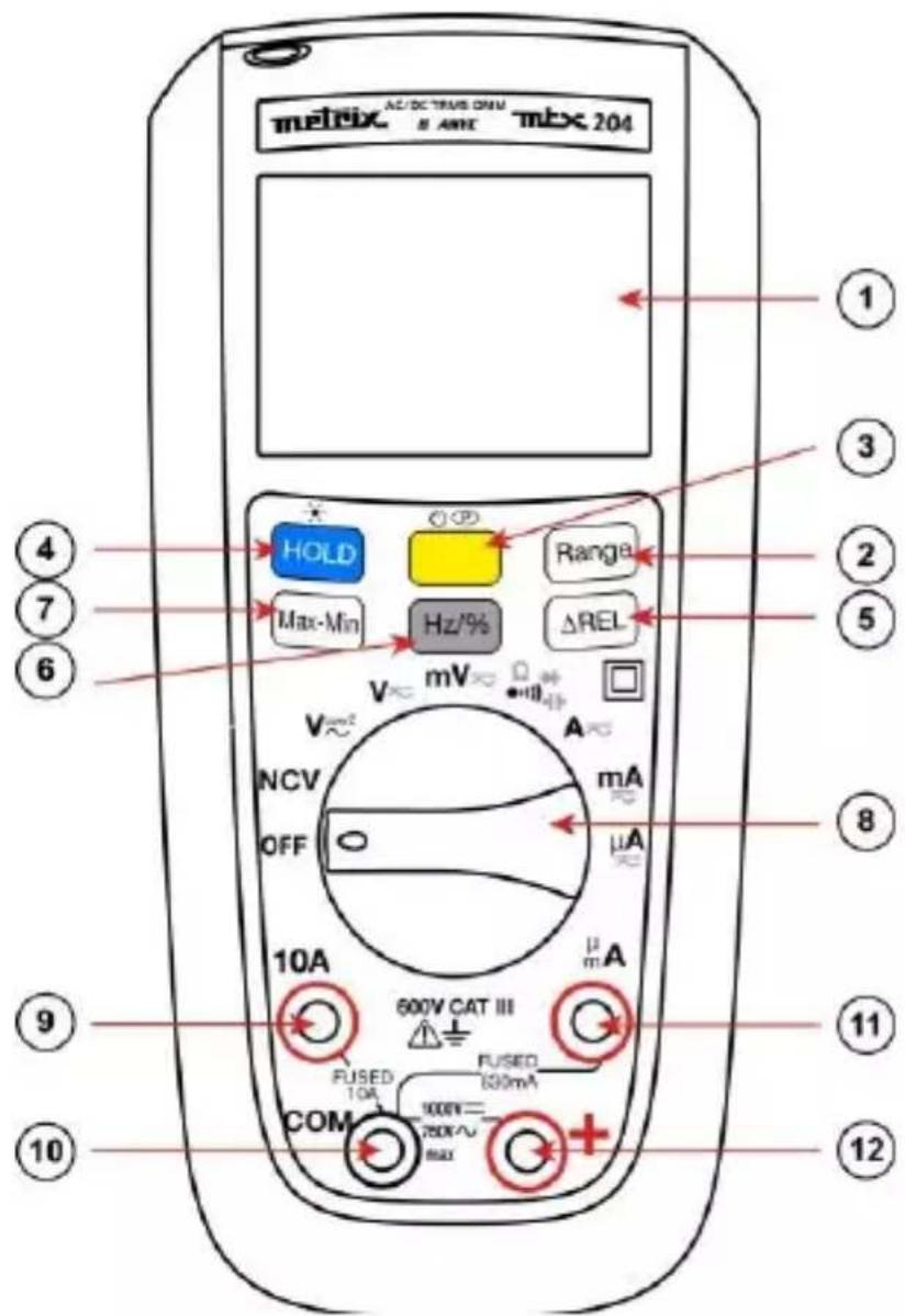
| 1 | Display (See §. 2.5). |
| 2 | Range key: operative in VAC, VDC, VLOWZ, Ω, C, AAC, ADC ranges.. |
| 3 | Yellow key: MODE AC/DC The AC+DC mode is selected (as default) in V and in A. • Switch to AC or DC mode by briefly pressing this key (short beep). • The current mode is displayed on the LCD. • To disable the Sleep mode, hold down when it is going the meter on. • Sleep mode is disabled and symbol (permanent) won't display any longer. |
| 4 | Hold key: • Holds the display on the current value and froozes it (short press). • A second short press returns the multimeter to normal mode. • This key is operative in all ranges (excepted NCV). |
| 5 | ΔREL key (relative mode) |
| 6 | Hz/% key (frequency/duty cycle) |
| 7 | Max-Min key |
| 8 | Switch. |
| 9 | Input terminal for AC and DC current measurement to 10A |
| 10 | Common (return) terminal for all measurements |
| 11 | Input terminal for voltage, resistance, continuity, diode, and capacitance measurements |
| 12 | Input terminal for AC, DC and AC+DC microamps and milliamp measurements to 600mA |
The appended table sums up the functions assigned to the keys and to the switch.
2.5. Display
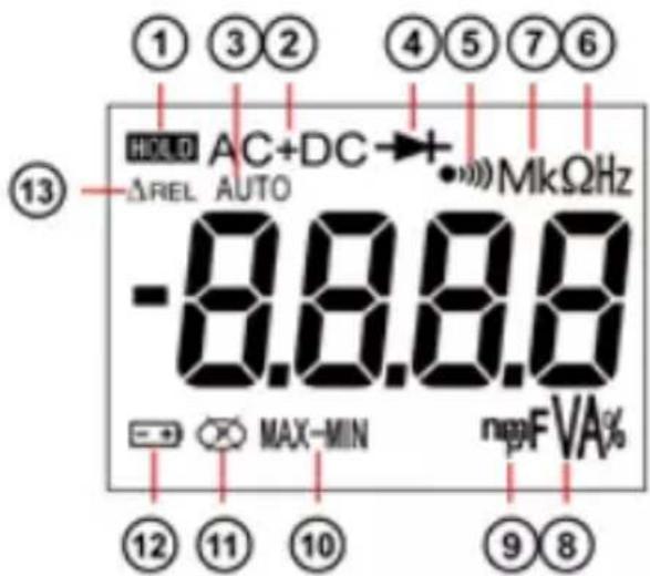
| Item | Description | Item | Description |
| 1 | Display Hold is enabled. | 8 | F, A, V, % – Farads, Amperes, Volts, or duty cycle |
| 2 | AC, DC or AC+DC voltage or current | 9 | n, m, μ decimal prefix |
| 3 | Auto measurement | 10 | Max-Min |
| 4 | Diode test is selected. | 11 | Autoshutdown is enabled. |
| 5 | Continuity measurement is selected | 12 | Battery is low and should be changed. |
| 6 | Ω (resistance) or Hz (frequency, AC only) | 13 | Relative mode |
| 7 | M, k - decimal prefix | ||
2.6. Fixation and stand
The meter can be used in different positions for a convenient and good reading:
- on the table
- on a wall, or an edge with the sheath supplied or with the optional Multifix accessory.
- on a metallic door with our magnetic sheath
- with the stand

2.
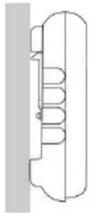
3.
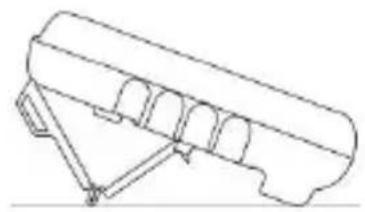
4.
3.1. Precautions for use
The operator and/or the responsible authority must carefully read and clearly understand the various precautions to be taken in use.
- Do not use the instrument in an explosive atmosphere or in the presence of inflammable gas or smoke.
- Do not use the instrument on networks with a rated voltage or category higher than those mentioned.
- Respect the maximum rated voltages and currents between terminals and in relation to the earth.
- Do not use the instrument if it seems damaged, incomplete or incorrectly closed
- Before each use, check the condition of the cable insulation, the unit and the accessories.
- All elements on which the insulation is damaged (even partially) must be put out of service for repair or disposed at waste.
- Use cables and accessories for voltage according to IEC 61010-2-031 and measurement categories at least equal to those of the instrument. If not, an accessory of a lower category reduces the category of the combined multimeter + accessory to that of the accessory.
- Respect the environmental conditions of use.
- Use personal protection equipment when conditions require it.
- Keep your hands and fingers away from the unused terminals of the device. When handling sensors or test probes, do not place fingers beyond physical finger guard.
3.2. First use
Place the batteries in the device as follows:
- Use a screwdriver, unscrew all the battery cover screws on the back of the meter.
- Place the batteries in the casing, respect polarity.
- Screw back battery cover screws

It is recommended to follow this procedure when you use the meter for the first time, or after long time without use:
- Start the meter; make sure that all segments are displayed.
Check that on Continuity position, and without any input the meter display OL. - Take out both cords and short circuit, the beeper should sound.
- Turn the rotary switch on V and check a known voltage (for example a battery) and make sure voltage is correct.
- When all the steps above are correct, you can start to use the meter.
3.3. Backlight and Torch light
Then pressing the (white) will light up

for more than 2s, both LCD backlight (blue) and torch light
Press again

more than 2s to shut down the backlight.
On NCV position the backlight will blink red if AC live voltage is detected.
As default, the multimeter is set to automatic mode (AUTO). Whatever the quantity being measured, pressing RANGE switches the instrument to manual mode to let you select the desired range.
3.4. Measuring AC, DC or AC+DC voltages

The meter measures AC or DC voltage. To minimize risk when measuring an unknown voltage, make sure to measure both AC and DC voltage
- Turn the rotary switch to

(10 MΩ),

(500 kΩ).

- Toggle between AC or DC voltage measurement by pressing the yellow button (in VlowZ : only AC measurement available).
- Connect the red test lead to the + terminal and the black test lead to the COM terminal.
- Measure the voltage by touching the probes to the desired test points of the circuit:

To avoid to measure ghost voltage, choose DMM is lower in Low Z (500 kΩ).

hce of the
There are two ranges in the mV setting. As default, the 600mV range is selected. Pressing RANGE switches the instrument to 60mV to measure weak voltages.
3.5. Measuring AC, DC or AC+DC current


- Turn the switch to , ,
- Toggle between AC or DC current measurement by pressing the yellow key.
- Connect the red test lead to either A, or mA/μA terminal and black test lead to the COM terminal.
- Break the circuit path to be measured. Then connect the test leads across the break and apply power.
- Read the measured current on the display.
Do not exceed the current limits: 10A in the 10A range and 630mA in the A and mA range.
MTX 204, 10A range
MTX 204, A range
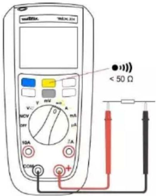
3.6. Measuring continuity
To avoid measurement errors and the risk of an electric shock, before making continuity measurements on a circuit, check that there is no voltage in the circuit.
- Turn the rotary switch to make sure power is disconnected from the circuit to be measured.
- Connect the red test lead to the + terminal and the black test lead to the COM terminal
- Detect the continuity by touching the probes to the desired point of the circuit, if the resistance is under 50 the beeper will sound, designating a short circuit. If the resistance is above 600 the meter displays OL, designating an open circuit.
3.7. Measuring resistance

To avoid measurement errors and the risk of an electric shock, before making resistance measurements on a circuit, check that there is no voltage in the circuit.
With the continuity mode selected, press the yellow button once to activate the resistance measurement. Touch with the test probes the desired point of the circuit and read the measured resistance on the display. If resistance is above 60MOhm the meter will display OL.
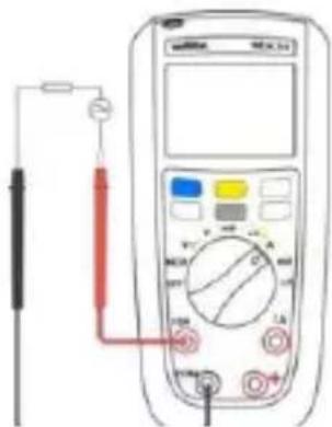
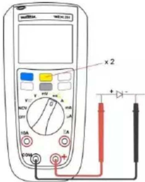
3.8. Testing Diodes

To avoid measurement errors and the risk of an electric shock, check, before testing diodes, that there is no voltage in the circuit.
- Turn the rotary switch to ma nthe power is disconnected from
the circuit to be measured.
- Press the yellow button twice.
- Connect the red test probe to the anode side and black test lead to the cathode side of the diode being tested.
- Read the forward bias voltage value on the display.
- If the polarity of the test leads is reversed with diode polarity or forward bias voltage is above 3V, the display reading shows OL.
This can be used to distinguish the anode and cathode sides of the diode.
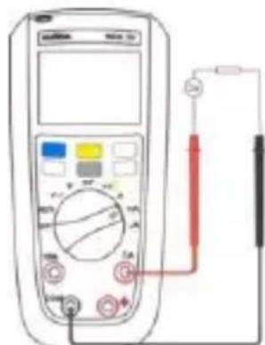
3.9. Measuring capacitance

To avoid measurement errors and the risk of an electric shock, before making
capacitance measurements on a circuit, check that there is no voltage in the circuit.
Only Autorange is available in this mode.

- Turn the rotary switch to ma sure power is disconnected from the circuit to be measured.
- Connect the red test lead to the + terminal and the black test lead to the COM terminal.
- Press the yellow button three times.
- Touch the probes to the capacitor leads.
- After allowing reading to stabilize, read the capacitance value on the display. capacitance range 100mF the measure can be
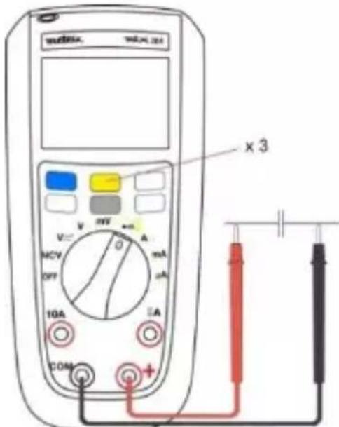
long and exceed 15s.
3.10. Non Contact Voltage Detection (NCV)

The NCV mode detects only AC voltages connected to the network with respect to ground. Always check for the presence of a voltage with a voltage measurement. To measure the absence of a voltage, use a VAT (www.chauvin-arnoux.com)
Network: 230V only, 50 Hz (sensitivity: 10 mV)
The meter can detect AC live voltage without contact. The NCV detection zone is displayed on the sheath.
- Remove all test leads from the Meter
- Turn the rotary switch to NCV
- Approach live conductor from LCD (position of the Meter may affect measurement)
If no AC live voltage is detected the Meter will display EF and product will be silent.
- If AC live voltage is detected product will show 4 different levels:
from - to ---, at - buzzer will sound discontinuously, at --- buzzer will sound continuously, and backlight will blink red. Basic detection voltage is for 220/230V.
- NCV is only for indication purpose and shouldn't be used for measurement, or to detect the absence of voltage.
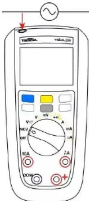

The NCV mode has an indicative meaning only and must not be used either for measuring nor detect the absence of voltage.
An engraved marking on the sheath indicates the position of the antenna for NCV indication.
3.11.VlowZ
The Vlow Z position measures AC voltage with lower impedance (500k) than normal voltage measurement, this function is used to avoid measuring ghost voltages.
3.12. Other measurements
- REL (relative mode)
Measures the relative difference. The relative mode is available for the VLowZ, V, mV, , C, A, mA, and A functions.
- Hz/% (frequency/duty cycle)
Selects measurement of the frequency or duty cycle.
In the AC voltage or current mode, press the Hz / % key repeatedly to display the
frequency or duty cycle mode or return to the normal mode.
Frequency measurement in Voltmeter and Ammeter operation is available up to 1kHz.
Max-Min
In measurement mode, press Max-Min repeatedly to display Max, Min, or Max-Min. A long press on Max-Min restores the normal mode.
4. TECHNICAL SPECIFICATIONS
Reference conditions
Temperature +23^± 3^
Humidity 45% to 75% RH
Supply Full battery (no low bat signal display) or accu.
1.5 VAA Ni-MH
Freq. for AC signal 45-65 Hz
Pure AC signal
Electric field < 1 V/m
Magnetic field < 40A / m
| MTX204 TRMS AC+DC | Accuracy | |||||
| Function | Display Range | Range | Resolution | AC | DC | AC+DC |
| ADP Voltage (mV) | 60,00 mV | 10 mV - 59,99 mV | 0,01 mV | 1%+6ct | 1%+6ct | 1%+6ct |
| 600,0 mV | 60,0 mV - 599,9 mV | 0,1 mV | ||||
| Voltage BP 1 kHz Volts (10 MΩ) VlowZ (500 kΩ- AC only) | 6,000 V | 0,6 V - 5,999 V | 0,001 V | 0.5%+4ct | 0.2%+2ct | 1.5%+4ct |
| 60,00 V | 60,0 - 59,99 V | 0,01 V | 1%+4ct | |||
| 600,0 V | 60,00 - 599,9 V | 0,1 V | ||||
| 750,0 V | 600 - 750 V | 1 V | ||||
| 1000 V | 600 - 1000 V | 1 V | 0.2%+2ct | |||
| Current μA input 100 Ω | 600.0 μA | 10 - 599.9 μA | 0.1 μA | 1%+5ct | 0.5%+3ct | 1%+5ct |
| 6000 μA | 600 -5999 μA | 1 μA | 0.5%+5ct | 0.5%+5ct | ||
| Current mA input 1 Ω | 60.00 mA | 6.00 - 59.99 mA | 0.01 mA | 0.5%+5ct | 0.5%+3pt | 0.5%+5ct |
| 600.0 mA | 60.0 - 599.9 mA | 0.1 mA | ||||
| Current A input 0.01 Ω | 6.000 A | 0.002 - 5.999 A | 0.001 A | 1%+5ct | 1%+5ct | 1%+5ct |
| 10.00 A | 6.000 - 10.00 A | 0.01 A | 0.5%+5ct | 0.5%+5ct | 0.5%+5ct | |
| Frequency Duty | 10 Hz | 2 - 9.99 Hz | 0.001 Hz | 0.1%+3 ct | ||
| 100 Hz | 10 - 99.99 Hz | 0.01 Hz | ||||
| 1 kHz | 100 - 999.9 Hz | 0.01 Hz | ||||
| Diode test | 3,000 V | 3,000 V | 0,001 V | 10% | ||
| Function | Display range | Range | Resolution | Accuracy |
| Resistance | 600,0 Ω | 0001 - 599,9 Ω | 0,1 Ω | 0.5% + 5ct |
| 6,000 kΩ | 0,600 - 5,999 kΩ | 0,001 kΩ | ||
| 60,00 kΩ | 6,00 - 59,99 kΩ | 0,01 kΩ | 1% + 5ct | |
| 600,0 kΩ | 6,00 - 599,9 kΩ | 0,1 kΩ | ||
| 6,000 MΩ | 0,600 - 5,999 MΩ | 0,001 MΩ | 3% + 5ct | |
| 60,00 MΩ | 06,00 - 59,99 MΩ | 0,01 MΩ | ||
| Capacitance | 10,00 nF | 1,000 - 9,999 nF | 1 pF | 10% + 10ct |
| 100,0 nF | 10,00 - 99,99 nF | 0,01 nF | 5% + 5ct | |
| 1.000 μF | 100.0 -999.9 nF | 0.1 nF | 2% +5ct | |
| 10.00 μF | 1.00 - 9.999 μF | 1 nF | ||
| 100.0 μF | 10.0 - 99.99 μF | 0.01 μF | ||
| 1.000 mF | 100.0 - 999.9 μF | 0.1 μF | ||
| 10 mF | 1.00 - 9.999 mF | 0.001 mF | 5%+5c t | |
| 100 mF | 10.00 mF - 99.9 mF | 0.01 mF | ||
| Continuity | 600 Ω | beep < 50 Ω -600 Ω | ||
| NCV | Non Contact Voltage detection | 230 V-50 Hz sensibility 10 mV | ||
5. SPECIFICATIONS
Environmental conditions
Reference temp. 23^ ± 3^
Use temperature - 20^ to 55^
Storage temp. - 40^ to 60^
Relative humidity
< 90 % RH (up to 45^ ) without condensation
Power supply
Batteries 2 x 1.5V AA/LR6/NEDA15A
Battery life approx. 500 hours in VLowZ / VAC without backlight
Mechanical features
Dimensions (with sheath) 170 × 80 × 50 ~mm
Weight 320g (with batteries)
Packing blister 266 x 132 x 70 mm
Protection rating IP 54
Compliance with international standards
Safety IEC 61010-1 / IEC 61010-2-031 / IEC 61010-2-033
EMC complies IEC 61326-1
Safety
Double insulation - class 2 insulation
Degree of pollution 2
Indoor use
Altitude <2000m
Category CAT-III, 600V max. with respect to ground
6. MAINTENANCE

Except for the fuse and the batteries, the instrument contains no parts that can be replaced by personnel who have not been specially trained and accredited. Any unauthorized repair or replacement of a part by an "equivalent" may gravely impair safety.
6.1. Cleaning
Disconnect the instrument completely and turn the rotary switch to OFF. Use a soft cloth, dampened with soapy water. Rinse with a damp cloth and dry rapidly with a dry cloth or forced air. Do not use alcohol, solvents, or hydrocarbons.
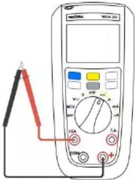
6.2. Testing the 10A Fuse

To avoid electrical shock, disconnect everything connected to the instrument and set the switch to OFF before replacing the fuses.
-
Turn the rotary switch to position and toggle the yellow key.
-
Plug a test lead into the ^+ terminal and touch the probe to the A or mA/μA according to the fuse to be tested.
-
A good A terminal fuse is indicated 000.0Ω to 000.2Ω.
-
If the display reads OL, replace the fuse and test again
-
If the display shows any other value, have the meter serviced.
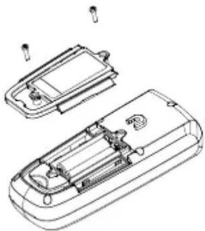
6.3. Replacement of the battery and fuse

To avoid false readings, which could lead to possible electric shock, or personal injury, replace the batteries with LR6 batteries as soon as the battery indicator appears
For safety reasons the fuse must always be replaced by an identical model.
Disconnect test leads before opening the battery door.
F1: Fast Fuse 630mA 1000V 10kA size : 6.3 x 32, UK standard
F2: Fuse 10A 1000V 30kA size : 10 x 38, UK standard
7. WARRANTY
Except as otherwise stated, our warranty is valid for 24 months starting from the date on which the equipment was sold. Extract from our General Conditions of Sale provided on request.
- The warranty does not apply in the following cases:
- Inappropriate use of the equipment or use with incompatible equipment;
- Modifications made to the equipment without the explicit permission of the manufacturer's technical staff;
- Work done on the device by a person not approved by the manufacturer;
- Adaptation to a particular application not anticipated in the definition of the equipment or not indicated in the user's manual;
- Damage caused by shocks, falls, or floods.
INHALT
EMC conform IEC 61326-1
Veiligheid
Isolatie
Freq. semnal c.a. 45-65 Hz
Semnal alternative pur
Campulelectric < 1V / m
Campul magnetic < 40A / m
| MTX204 TRMS AC+DC | Precizie | |||||
| Funcție | Interval afișare | Domeniu | Rezoluție | AC | DC | AC+DC |
| Tensiune ADP (mV) | 60,00 mV | 10 mV - 59,99 mV | 0,01 mV | 1%+6ct | 1%+6ct | 1%+6ct |
| 600,0 mV | 60,0 mV - 599,9 mV | 0,1 mV | ||||
| Tensiune BP 1 kHz Volți (10 MΩ) | 6,000 V | 0,6 V - 5,999 V | 0,001 V | 0.5% + 4ct | 0.2%+2ct | 1.5%+4ct |
| 60,00 V | 60,0 - 59,99 V | 0,01 V | 1%+4ct | |||
| VlowZ (500 kΩ numai c.a.) | 600,0 V | 60,00 - 599,9 V | 0,1 V | |||
| 750,0 V | 600 - 750 V | 1 V | ||||
| 1000 V | 600 - 1000 V | 1 V | 0.2%+2ct | |||
| Current μA Intrare 100 Ω | 600.0 μA | 10 - 599.9 μA | 0.1 μA | 1%+5ct | 0.5%+3ct | 1%+5ct |
| 6000 μA | 600 -5999 μA | 1 μA | 0.5%+5ct | 0.5%+5ct | ||
| Current mA intrare 1 Ω | 60.00 mA | 6.00 - 59.99 mA | 0.01 mA | 0.5%+5ct | 0.5%+3ct | 0.5%+5ct |
| 600.0 mA | 60.0 - 599.9 mA | 0.1 mA | ||||
| Current A intrare 0.01 Ω | 6.000 A | 0.002 - 5.999 A | 0.001 A | 1%+5ct | 1%+5ct | 1%+5ct |
| 10.00 A | 6.000 - 10.00 A | 0.01 A | 0.5%+5ct | 0.5%+5ct | 0.5%+5ct | |
| Frecvență Ciclu | 10 Hz | 2 - 9.99 Hz | 0.001 Hz | 0.1%+3ct | ||
| 100 Hz | 10 - 99.99 Hz | 0.01 Hz | ||||
| 1 kHz | 100 - 999.9 Hz | 0.01 Hz | ||||
| Testare diode | 3,000 V | 3,000 V | 0,001 V | 10% | ||
| Funcție | Interval afișare | Domeniu | Rezolutie | Precizie |
| Rezistență | 600,0 Ω | 0001 - 599,9 Ω | 0,1 Ω | 0.5% + 5ct |
| 6,000 kΩ | 0,600 - 5,999 kΩ | 0,001 kΩ | ||
| 60,00 kΩ | 6,00 - 59,99 kΩ | 0,01 kΩ | 1% + 5ct | |
| 600,0 kΩ | 6,00 - 599,9 kΩ | 0,1 kΩ | ||
| 6,000 MΩ | 0,600 - 5,999 MΩ | 0,001 MΩ | 3% + 5ct | |
| 60,00 MΩ | 06,00 - 59,99 MΩ | 0,01 MΩ | ||
| Capacitanță | 10,00 nF | 1,000 - 9,999 nF | 1 pF | 10% + 10ct |
| 100,0 nF | 10,00 - 99,99 nF | 0,01 nF | 5% + 5ct | |
| 1.000 μF | 100.0 -999.9 nF | 0.1 nF | 2% +5ct | |
| 10.00 μF | 1.00 - 9.999 μF | 1 nF | ||
| 100.0 μF | 10.0 - 99.99 μF | 0.01 μF | ||
| 1.000 mF | 100.0 - 999.9 μF | 0.1 μF | ||
| 10 mF | 1.00 - 9.999 mF | 0.001 mF | 5%+5ct | |
| 100 mF | 10.00 mF - 99.9 mF | 0.01 mF | ||
| Continuitate | 600 Ω | beep < 50 Ω -600 Ω | ||
| NCV | Detectarea tensiunii fără contact | 230 V-50 Hz sensibilitate 10 mV | ||
5. CHARACTERISTICIGENERALE
Characteristic Mechanism
Dimensiuni 170× 80× 50mm
CEM conform IEC 61326-1
Kateropn n3MepeHnI l COOTBeTCTByeT n3MepeHnM, BbIOJIHReMbIM Ha ceTeBOy yCTaHOBKe 3daHnI.
Ipumep: pacnpedenumelbHbui um, npepbiaamenu, cmauohaphe ycmaHOku unu obopydoaue dner npomblneHHO2o uCNOb30aHua.
Kateropn n3mepenna II COOTBETCTByet n3mepeHnM, BblnoJHReMbIM Ha uejx, Haprymyo coeDInHeHHbIX C Hn3KOBoTHOcTeBOy yCTaHOBkoN.
Ipumep: 6noku numaHua 6bimobbix npubopoe u nopamuehozo uHcmpymehma.
2. O3HAKOMJIEHNE
2.1. CoctoHne noCTaBKn
Heo6xOIMO npOBepntb KOMJIeKTHOCTb NOCTaBKN B COOTBeTCTBn C BaIIM 3aKa3OM.
PykoBoDCTBO no 3KcIpyatauHa HeCKOJIbKnx Ra3bIkaX Ha 6ymaxHOM HocNTeJe.
KOMJIeKTn326aTaapeekAAHa1,5B
KpaChbI nCnblTaTeJIbHbI npOBoD dInHOi 1,5 M co uynamn
- YepHbI nCnblTaTeNbHbI npOBoD dNHOH 1,5 M co yynaM
2.2. BcnoMOratelbHbIe npHaIeXHoCTn n 3aNactn
3anyactn
KOMnIeKT n3MePHTeNbHbIX npOBOOB (KpaCHbI/YePbI) C yrIOBbIMN uTeKepaMn Tnna «6aHaH» B o6oJouKe n3 PBX
KOMJIeKT N3MePHTeJIbHbIX IPOBOIOB (KpaCHbI/YePHbI) C yrJIOBbIMN WTeKepaMn TUNa «6aHaH» B CNJIHKOHOBO IOBNoUKe
BcnoMoraTeIbHbIe npHaIeJXHOCTn
I3mepntenbHbIe yynbI KAT. III/IV
3axmbi Tnna KpokoJN
NcnoJb3OBaTbCdIg N3MepeHn IIN ONpeJeHn OTCyTCTBn
Hanpajxehn. Mapknpobka Ha yexne yka3bIbaeT paCNOIOXeHne aHTeHHbl IJIy Hndkaun B pexime NCV.
- Hz/% (yactota/ko3000000000000000000000000000000000000000000000000000000000000000000000000000
No3BOJnE T BbI6paTb peKIM n3MepeHnA cactOtbl Nn KOaΦnCneHTa 3anONHeHn.
B pexime n3mepenHnnpjkeHn nn nepem. Toka Heo6xOIMO HeckoIbKO pa3 HaxaTb Ha KhoNkU Hz/% dIy OTo6paKeHnpeKIMa n3MepeHn YacTObl, KO3ΦΦnCHeNTa 3anOpJHEnHn nn dIy BO3BpTa B HopMaJIbHbI peKIM.
I3MepeHne YacToTbIBpeXnME BOJbTMeTp aAmpeMepTa BO3MOxHO B DnaNa3OHe Do 1 Kt.
Max-Min
B peKIme n3MpeHn cIeNyEt HeCKoJIbKO pa3 HaKaTb Ha KHOIp Ky Max-Min IJRA OTO6paXeHn MaKcIMaJIbHOrO, MInHMaJIbHOrO 3HaueHn rNn pa3HOCTn MeJy MaKcIMaJIbHbIM N MInHMaJIbHbIM 3HaueHnEe. DOnrOe HaxaTne Ha KHOIp Ky Max-Min IO3BOJraT BepHyTbcR B HopMaJIbHbI peKIm.
4. TEXHnueCKne XAPAKTEPNCNIKNI
IcxOaHbIe ycIOBnA
TemnepaTpa +23^ ± 3^
BnaXHocTb
OT 45% Do 75%
NCTOCHNKIITAHNA
Hobar 6atapeika (OTCYTCTBNE CNHaNa O Hn3KOM
Yactota cnHana nepem. Toka
3apae) nnn akkymyIaTOp 1,5B AA Ni-MH
CunhaI nepemehnhoro
MaHnTHoe nOJe < 40 B/M
3NeKtpnueckoe none < 1 B/M
| MTX204 TRMS AC+DC | Погревностб | |||||
| Фунreichа | Диапазон Индikаши ч. | Диапазон | РазPECе нieves | AC | DC | AC+DC |
| Нарожени ADP (mV) | 60,00 mV | 10 mV - 59,99 mV | 0,01 mV | 1%+6ct | 1%+6ct | 1%+6ct |
| 600,0 mV | 60,0 mV - 599,9 mV | 0,1 mV | ||||
| Нарожени ВР 1 кГ Вовты (10 MОм) VlowZ (500 кОм Толъко пэрь. ТOK) | 6,000 V | 0,6 V - 5,999 V | 0,001 V | 0.5% + 4ct | 0.2%+2ct | 1.5%+4ct |
| 60,00 V | 60,0 - 59,99 V | 0,01 V | 1%+4ct | |||
| 600,0 V | 60,00 - 599,9 V | 0,1 V | ||||
| 750,0 V | 600 - 750 V | 1 V | ||||
| 1000 V | 600 - 1000 V | 1 V | 0.2%+2ct | |||
| Сида тoka, мКА вхOD, 100 Oм | 600.0 μA | 10 - 599.9 μA | 0.1 μA | 1%+5ct | 0.5%+3ct | 1%+5ct |
| 6000 μA | 600 -5999 μA | 1 μA | 0.5%+5ct | 0.5%+5ct | ||
| Сида тoka, мА вхOD, 1 Oм | 60.00 mA | 6.00 - 59.99 mA | 0.01 mA | 0.5%+5ct | 0.5%+3ct | 0.5%+5ct |
| 600.0 mA | 60.0 - 599.9 mA | 0.1 mA | ||||
| Сида тoka, A вхOD, 0,01 Oм | 6.000 A | 0.002 - 5.999 A | 0.001 A | 1%+5ct | 1%+5ct | 1%+5ct |
| 10.00 A | 6.000 - 10.00 A | 0.01 A | 0.5%+5ct | 0.5%+5ct | 0.5%+5ct | |
| Частota Козфциент Започенья | 10 Hz | 2 - 9.99 Hz | 0.001 Hz | 0.1%+3ct | ||
| 100 Hz | 10 - 99.99 Hz | 0.01 Hz | ||||
| 1 kHz | 100 - 999.9 Hz | 0.01 Hz | ||||
| Проберka Псюлов | 3,000 V | 3,000 V | 0,001 V | 10% | ||
| Фунreichnia | Диапазон Иndидаци | Диапазон | Раз Archaeи | Погревность |
| Соротавлике | 600,0 Ω | 0001 - 599,9 Ω | 0,1 Ω | 0.5% + 5ct |
| 6,000 kΩ | 0,600 - 5,999 kΩ | 0,001 kΩ | ||
| 60,00 kΩ | 6,00 - 59,99 kΩ | 0,01 kΩ | 1% + 5ct | |
| 600,0 kΩ | 6,00 - 599,9 kΩ | 0,1 kΩ | ||
| 6,000 MΩ | 0,600 - 5,999 MΩ | 0,001 MΩ | 3% + 5ct | |
| 60,00 MΩ | 06,00 - 59,99 MΩ | 0,01 MΩ | ||
| Емковские | 10,00 nF | 1,000 - 9,999 nF | 1 pF | 10% + 10ct |
| 100,0 nF | 10,00 - 99,99 nF | 0,01 nF | 5% + 5ct | |
| 1.000 μF | 100.0 -999.9 nF | 0.1 nF | 2% +5ct | |
| 10.00 μF | 1.00 - 9.999 μF | 1 nF | ||
| 100.0 μF | 10.0 - 99.99 μF | 0.01 μF | ||
| 1.000 mF | 100.0 - 999.9 μF | 0.1 μF | ||
| 10 mF | 1.00 - 9.999 mF | 0.001 mF | 5%+5ct | |
| 100 mF | 10.00 mF - 99.9 mF | 0.01 mF | ||
| Пробовка | 600 Ω | beep < 50 Ω -600 Ω | ||
| NCV | Бесло tackтое onpeдelloпeне наличe наразожения | 230 V-50 Hz ЧУВСТВИТ 10 mV | ||
5. OБICIЕ XAPAKTEPNUKTUN
YcnoBnOkpykaOuSeCpebl
IcxoHa TaemepaTypa 23^± 3^
Pa6oay Tempepatya ot-20°C do 55°C
TeMnepaTpa xpaHnna 0T-40°C,do 60°C
OTHOCHTeJIbHaB BnAaXHoCTb <90% (D0 45°C) 6e3 KOHdEHCaUN
NCTOCHNK NHTAHNA
Батуарки 2x1,5B AA/LR6/ NEDA15A
ДиTeJIbHOCTb aBTOHOMHOn pa6Otbl OT 6aTapeek Okono 500 yacOB b peXnme VLowZ/VAC 6e3 noDCBeTKn 3KpaHa
Mexahnueckne xapaKtepcntkn
Pa3Mepbl 170×80×50 MM
Macca
320r(c6aTapeiKaMn)
YnakoBka 266x132x70 MM
CTeeneb 3aunTbI IP54
COOTBeTCTBnE MekdyHapOndbIM CtaHdApTaM
Be3onacHOCTb
IEC 61010-1 / 61010-2-031 / IEC 61010-2-033
3MC COOTBeTCTBnE cTaHdApTy IEC 61326-1
Бeэzonachoctb
I30JIaIy IBOHnA I3OJIaIy,Knacc 2
Cteenb 3aarp3HeHH 2
IcnoJb3OBaHHeBHyTpN nOmeUeHn
BbIcota naI ypOBHem Mopra <2000M
Kateropn KAT. III, 600B mAcC. c 3a3eMJIeHneM
6. TEXHnueCKOE OBCJIyXmBAHne

3a ncknueHnem npedoxpaHnteI n aKKymJrTOphbIX 6atapei (3a NCKJIIOUeHnEM 6batapeK), npnbop He coepjNT deTaIeN, 3ameHy KOTOpbIX MOKeT pON3BOIDtB HeOByeHHbI N HeyNOJHOMOeHHbI nepcoHaI. JIO6oe HecahkCIOHOpOBaHHoe BblONHeHne pa60 T NO TexHnueCKOMy 06cnyKBaHHo, a TaKke 3aMeHa DeTaIeN aHaJOrnHbIMN 3aAnactMIM MOKeT cepBe3HO cKa3aTbCra Ha 6e3OnaCHOCTN.
6.1.Чистka
OTcoeHNHTb OT np6opa BCE NOdkJIOueHn yUCTaHOBNTb nepeKIOuAteIb B nOIOxHe NcnoJIb3OBaTb MArKyIO BeTOuB, CJeRka CMOueHHyIO B MbInbHO BOE. IpotepeTB np6op BnaXHOB BeTouBIO, a 3aTeM 6bICTPO BBITEpeTB
Hacyxo cyxoi BeToobu nn o6daTb ctpyei BO3dyxa. He nCnoB3ObaTb cnpt, pactBopnte nn nn yrneBOdoPOn.
Our international contacts
www.chauvin-amoux.com/contactss

CHAUVIN ARNOUX
CHAAHAP