Hydro HG10 - Computer cooling system CORSAIR - Free user manual and instructions
Find the device manual for free Hydro HG10 CORSAIR in PDF.
| Product Type | Liquid Cooling Bracket for Graphics Card |
| Brand | Corsair |
| Model | Hydro HG10 N780 |
| Dimensions (L × W × H) | 244 mm × 100 mm × 31 mm |
| Weight | Approximately 150 g (estimated) |
| Material | Plastic and metal |
| GPU Compatibility | NVIDIA GeForce graphics cards (N780 models and similar) |
| Cooler Compatibility | Corsair Hydro liquid coolers (H75, H105, H100i, etc.) |
| Temperature Reduction | Up to 45°C over the stock heatsink |
| Integrated Fan | Reuses the original GPU fan |
| Shroud | Removable, guides airflow |
| Thermal Pads | Pre-installed to cool surface components |
| Kit Contents | Card screws, spacers, thumb screws, shroud, etc. |
| Installation | Replaces the stock cooler, mounts the Hydro cooler and fan |
| Power | Via the GPU fan connector |
| Speed Control | Automatic via GPU temperature |
| Maintenance | Clean the thermal paste with isopropyl alcohol and a lint-free cloth |
| Safety | Removing the original cooler may void GPU warranty; use with caution |
| Warranty | See GPU manufacturer's warranty; Corsair is not responsible for damage |
| Customer Support | http://corsair.force.com for return inquiries |
Frequently Asked Questions - Hydro HG10 CORSAIR
User questions about Hydro HG10 CORSAIR
0 question about this device. Answer the ones you know or ask your own.
Ask a new question about this device
Download the instructions for your Computer cooling system in PDF format for free! Find your manual Hydro HG10 - CORSAIR and take your electronic device back in hand. On this page are published all the documents necessary for the use of your device. Hydro HG10 by CORSAIR.
USER MANUAL Hydro HG10 CORSAIR
natural_image
Technical line drawing of a mechanical device casing with internal gear and mounting holes (no text or symbols)INSTALLATION GUIDE GUIDE D'INSTALLATION INSTALLATIONSANLEITUNG GUIDAALL'INSTALLAZIONE GUÍA DE INSTALACIÓN РУКОВОДСТВО ПО УСТАНОВКЕ 安装指南
HG10
HYDRO SERIES HG10 GPU LIQUID COOLING BRACKET
N780 EDITION
English: 1 - 9
Français: 10 - 18
Deutsch: 19 - 27
Italiano: 28 - 36
Español: 37 - 45
Россию: 46 - 54
中文: 55 - 63
Table of Contents
Congratulations: 2
Bracket specificaitons: 2
Accessory kit contents: 2
Bracket features: 3
Warranty information: 4
Remove your stock heatsink: 4
Remove the stock blower: 5
Install the stock blower: 5
Install the fan shroud:....6
Install the bracket: 6
Install the Hydro CPU Cooler Mounting Bracket: 7
Install the Hydro CPU Cooler Standoffs: 7
Install the Hydro CPU Cooler: 8
Frequently asked questions: 9
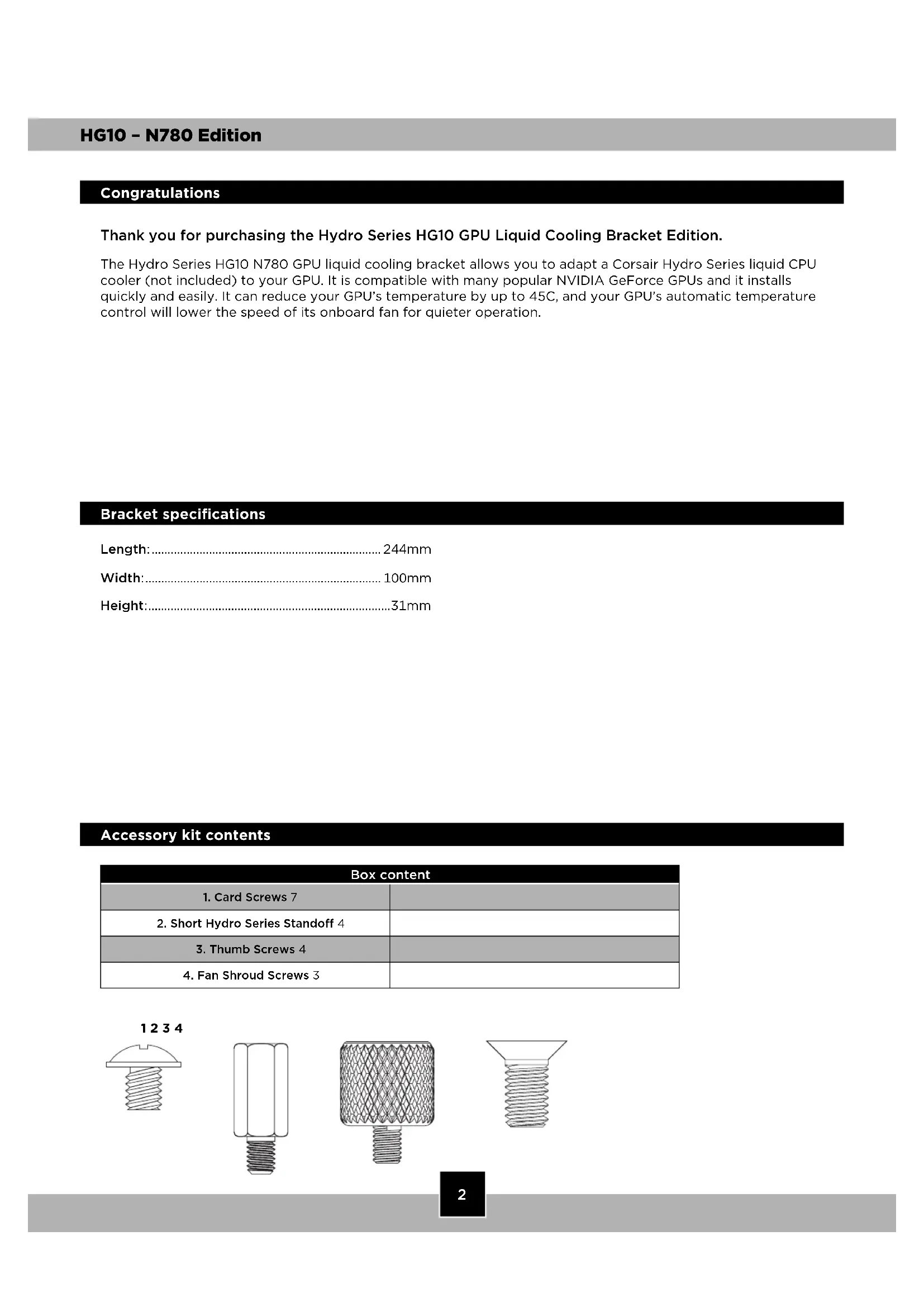
Congratulations
Thank you for purchasing the Hydro Series HG10 GPU Liquid Cooling Bracket Edition.
The Hydro Series HG10 N780 GPU liquid cooling bracket allows you to adapt a Corsair Hydro Series liquid CPU cooler (not included) to your GPU. It is compatible with many popular NVIDIA GeForce GPUs and it installs quickly and easily. It can reduce your GPU's temperature by up to 45C, and your GPU's automatic temperature control will lower the speed of its onboard fan for quieter operation.
Bracket specifications
Length: 244mm
Width: 100mm
Height: 31mm
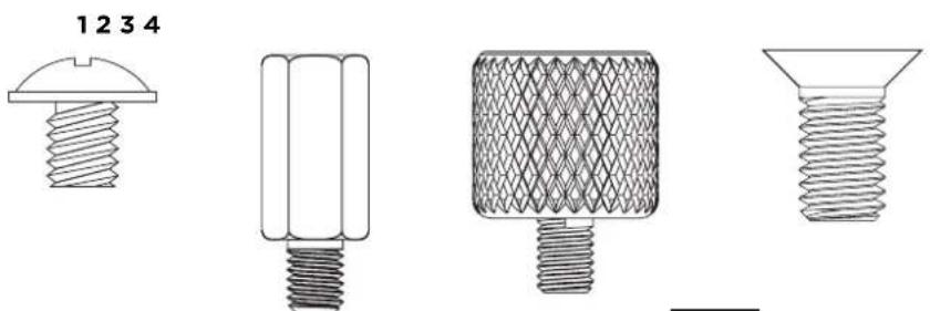
Accessory kit contents
| Box content | |
| 1. Card Screws 7 | |
| 2. Short Hydro Series Standoff 4 | |
| 3. Thumb Screws 4 | |
| 4. Fan Shroud Screws 3 | |
natural_image
Four technical drawings of screw components with different threaded designs, no text or symbols presentBracket Features
A. Reuse your GPU's stock fan with the removable fan shroud.
B. Stylized cooling bracket compatible with all Hydro Series Liquid CPU Coolers.
C. Preinstalled thermal pads help cool surface PCB components.
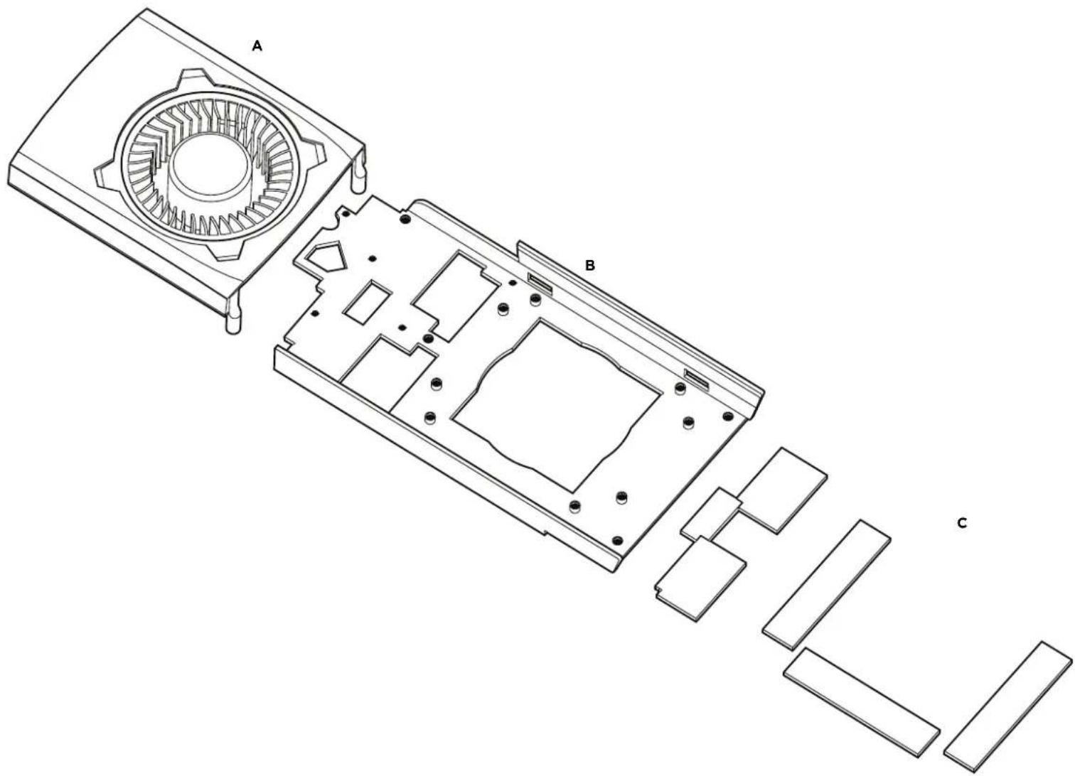
text_image
Technical diagram of a device's internal structure with labeled components A, B, and CWarranty Information
Please refer to your GPU manufacturer's manual regarding warranty information. Removing the stock heatsink may void the warranty. Corsair will not be held responsible for any damaged or destroyed GPUs due to the use of the Hydro Series HG10 GPU Liquid Cooling Bracket.
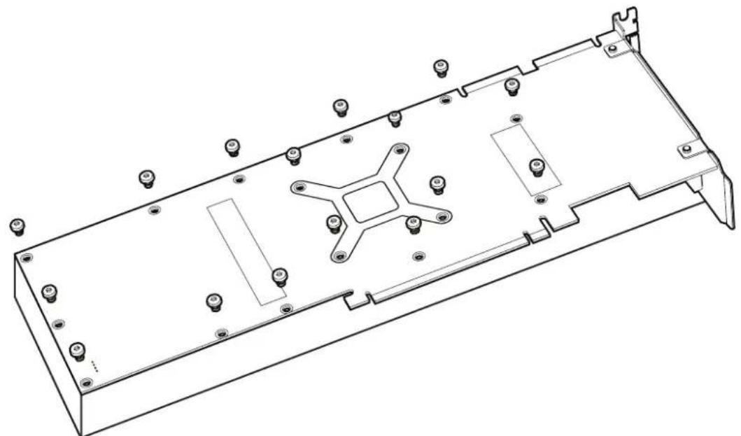
1. Remove your stock heatsink
First, carefully uninstall your card's stock heatsink by removing all of the screws on the bottom and bracket of the card. Once the screws have been removed, gently lift the heatsink away from the card and unplug the stock blower fan. Remove all excess thermal tape still attached to the graphics card and clean off any thermal paste remaining on the GPU die.
We recommend using cotton balls, swabs, or pads with high purity isopropyl alcohol when cleaning the thermal paste off the die.
natural_image
Technical line drawing of a mechanical housing or enclosure with mounting holes and internal components (no text or symbols)2. Remove the stock blower
Now that the stock blower has been unplugged, remove the stock blower from the heatsink by unscrewing the three screws underneath the blower. Make sure to keep the screws from the stock heatsink, we will use these for the next step.

natural_image
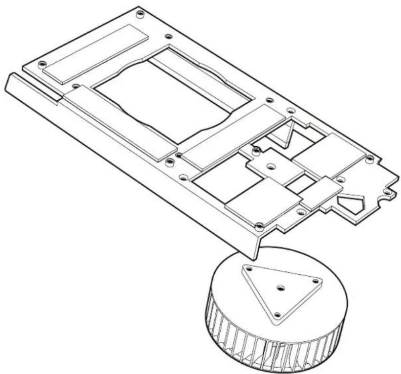
Technical line drawing of a mechanical component with bolt holes and internal cavities (no text or symbols)3. Install the stock blower
Next, route the stock fan blower cable through the HG10 bracket and secure the blower to the bracket using the same screws from the previous step.
natural_image
Technical line drawing of a mechanical device with internal components and a circular base component (no text or symbols)4. Install the fan shroud
Now that the stock blower has been installed onto the bracket, place the HG10 fan shroud onto the bracket and tighten the four screws to secure.

natural_image
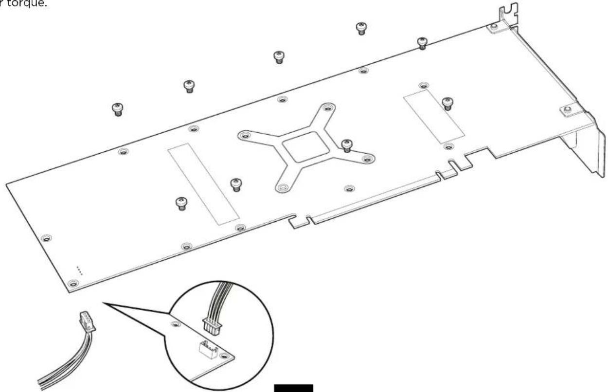
Technical line drawing of a mechanical or electronic component with multiple rectangular cutouts and mounting holes (no text or symbols)5. Install the bracket
Reconnect the stock blower's power cable to the card and mount the bracket onto the card. Next, use the provided M3 screws to secure the bracket. Hand tighten the screws until the bracket is snug, but do not over torque.
natural_image
Technical line drawing of an electronic device casing with internal components and a magnified inset showing cable assembly (no text or symbols)6. Install the Hydro CPU Cooler Mounting Bracket
Now that the HG10 has been mounted, you can use either the AMD or Intel mounting bracket from a Hydro Series Liquid CPU Cooler to secure it to the card.

natural_image
Technical line drawing of a mechanical component with circular and rectangular features (no text or symbols)7. Install the Hydro CPU Cooler Standoffs
Next, select what standoffs to install into the HG10.
For Corsair Hydro Series liquid CPU coolers with the round-shaped pump head (such as the H75 or H105), use the short standoffs.
For Corsair Hydro Series liquid CPU coolers with a square-shaped pump head (such as the H100i) no standoffs are required.
short standoffs
8. Install the Hydro CPU Cooler
Lastly, secure the Hydro CPU Cooler's mounting bracket using the provided thumbscrews.

natural_image
Technical line drawing of a mechanical component with mounting flanges and a threaded knob (no text or symbols)Installation Complete
Please refer to your Hydro Series Liquid CPU Cooler's manual or the HG10 product page on Corsair.com for more information regarding mounting locations.
Frequently Asked Questions
- Does the new Corsair Hydro CPU Cooler fit on my HG10?
Please go to Corsair.com and check the HG10 product page for compatibility information.
- Who should I contact if I received my bracket damaged or my GPU is no longer working?
While we do not provide GPU support, please go to http://corsair.force.com and request an RMA so that we can replace the damaged bracket. Contact your GPU's manufacturer for GPU troubleshooting.
Table des matières
Félicitations:....11
Foire aux questions:....18
Félicitations!
natural_image
Four technical drawings of screw components with different threaded designs, no text or symbols presenttext_image
Technical diagram of a device's internal structure with labeled components A, B, and Cnatural_image
Technical line drawing of a mechanical housing or enclosure with mounting holes and internal components (no text or symbols)natural_image
Technical line drawing of a mechanical component with bolt holes and internal cavities (no text or symbols)natural_image
Technical line drawing of a mechanical assembly with internal components and a circular base (no text or symbols)natural_image
Technical line drawing of a mechanical or electronic component with multiple rectangular cutouts and mounting holes (no text or symbols)5. nstation du support
natural_image
Technical line drawing of a mechanical component with circular and rectangular features (no text or symbols)natural_image
Technical line drawing of a mechanical component with mounting flanges and a threaded knob (no text or symbols)natural_image
Technical drawings of four different screw components with no visible text or symbolstext_image
Technical diagram of a device's internal structure with labeled components A, B, and CGarantie
natural_image
Technical line drawing of a mechanical housing or enclosure with mounting holes and internal components (no text or symbols)natural_image
Technical line drawing of a mechanical component with bolt holes and internal cavities (no text or symbols)natural_image
Technical line drawing of a mechanical assembly with internal components and a circular base (no text or symbols)natural_image
Pure technical line drawing of a mechanical or architectural component outline without any text, numbers, or symbolsnatural_image
Technical line drawing of an electronic device casing with connectors and a close-up inset showing cable routing (no text or symbols)natural_image
Technical line drawing of a mechanical component with circular and rectangular features (no text or symbols)natural_image
Technical line drawing of a mechanical component with mounting flanges and a threaded knob (no text or symbols)natural_image
Four technical drawings of screw components with different threaded designs, no text or symbols presenttext_image
Technical diagram of a device's internal structure with labeled components A, B, and Cnatural_image
Technical line drawing of a mechanical housing or enclosure with mounting holes and internal components (no text or symbols)natural_image
Technical line drawing of a mechanical component with bolt holes and internal cavities (no text or symbols)natural_image
Technical line drawing of a mechanical component with internal cavities and mounting holes, showing no text or symbols.natural_image
Technical line drawing of a mechanical or electronic component with multiple rectangular cutouts and mounting holes (no text or symbols)natural_image
Technical line drawing of an electronic device casing with connectors and wiring, showing internal components and mounting holes (no text or symbols)natural_image
Technical line drawing of a mechanical component with circular and rectangular features (no text or symbols)natural_image
Technical line drawing of a mechanical component with mounting flanges and a threaded bolt (no text or symbols)natural_image
Technical drawings of four different screw components with no visible text or symbolstext_image
Technical diagram of a device's internal structure with labeled components A, B, and Cnatural_image
Technical line drawing of a mechanical housing with mounting holes and internal components (no text or symbols)natural_image
Technical line drawing of a mechanical component with bolt holes and internal cavities (no text or symbols)natural_image
Technical line drawing of a mechanical assembly with internal components and a circular base (no text or symbols)natural_image
Technical line drawing of a mechanical or electronic component with multiple rectangular cutouts and mounting holes (no text or symbols)natural_image
Technical line drawing of a mechanical component with circular and rectangular features (no text or symbols)natural_image
Technical line drawing of a mechanical component with mounting flanges and a threaded knob (no text or symbols)natural_image
Four technical drawings of screw components with different threaded designs, no text or symbols presentОсобенности модуля
text_image
Technical diagram of a device's internal structure with labeled components A, B, and Cnatural_image
Technical line drawing of a mechanical housing with mounting holes and internal components (no text or symbols)natural_image
Technical line drawing of a mechanical component with bolt holes and internal cavities (no text or symbols)natural_image
Technical line drawing of a mechanical assembly with a circular base and internal components (no text or symbols)natural_image
Technical line drawing of a mechanical or electronic component with multiple rectangular cutouts and mounting holes (no text or symbols)5. Установка модуля
natural_image
Technical line drawing of a mechanical component with circular and rectangular features (no text or symbols)natural_image
Technical line drawing of a mechanical component with mounting flanges and a threaded knob (no text or symbols)Установка завершена
natural_image
Four technical drawings of screw components with different threaded designs, no text or symbols present指旋螺丝
text_image
Technical diagram of a device's internal structure with labeled components A, B, and C保修信息
natural_image
Technical line drawing of a mechanical housing or enclosure with mounting holes and internal components (no text or symbols)2. 拆下现有风扇
natural_image
Technical line drawing of a mechanical component with bolt holes and internal cavities (no text or symbols)3. 安装现有风扇
natural_image
Technical line drawing of a mechanical assembly with internal components and a circular base (no text or symbols)4. 安装风扇保护罩
natural_image
Technical line drawing of a mechanical or electronic component with multiple rectangular cutouts and mounting holes (no text or symbols)5. 安装支架
natural_image
Technical line drawing of an electronic device casing with connectors and wiring, showing internal components and mounting holes (no text or symbols)natural_image
Technical line drawing of a mechanical component with circular and rectangular features (no text or symbols)natural_image
Technical line drawing of a mechanical component with mounting flanges and a threaded knob (no text or symbols)安装完成
EMAIL: support@corsair.com
FACEBOOK: facebook.com/corsairmemory
BLOG: corsair.com/blog/

FORUM: forum.corsair.com
TWITTER: twitter.com/corsairmemory
USA and CANADA: (800) 205-7657 | INTERNATIONAL: (510) 657-8747 | FAX: (510) 657-8748

CORSAIR®
47100 Bayside Parkway • Fremont • California • 94538 • USA | corsair.com