
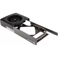
XD7 RGB - Computer cooling system CORSAIR - Free user manual and instructions
Find the device manual for free XD7 RGB CORSAIR in PDF.

| Product Type | Water Cooling Pump with Integrated Reservoir |
| Brand | Corsair |
| Model | XD7 RGB |
| Dimensions (approx.)* | 130 mm x 80 mm x 80 mm |
| Weight (approx.)* | 500 g |
| Materials | Copper, brass |
| Power | 4-pin Molex connector (12 V) |
| RGB Connectivity | Addressable RGB connector (series/direct); ARGB adapter for motherboard included |
| Pump Control | 4-pin PWM (requires iCUE Commander PRO for automatic control) |
| Temperature Sensor | G1/4" sensor included, compatible with iCUE Commander PRO |
| Fittings | G1/4" ports (4 fittings provided, caps included) |
| Max Flow Rate | Not specified |
| Reservoir Volume | Approximately 100 ml (fill to 4 cm from top) |
| Lighting | Addressable RGB, compatible with iCUE (via Commander PRO or Lighting Node PRO) |
| Operating Temperature | 0 °C to +40 °C |
| Warranty | Manufacturer's warranty (excluding damage from incorrect installation) |
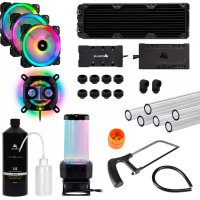
| Package Contents | XD7 RGB pump/reservoir, ATX 24-pin jumper bridge, G1/4 fittings (x4), temperature sensor fitting, M4 x 8 mm screws (x12), fitting tool, ARGB adapter cable |
| Maintenance and Cleaning | Minimum 24-hour leak test; fill with Corsair XL cooling liquid; do not let pump run dry |
| Safety | Do not disassemble; avoid short circuits; use only with copper/brass components |
| Spare Parts and Repairability | Spare parts available at corsair.com; disassembly not recommended |
| General Information | Requires a complete custom cooling loop; compatible with iCUE; not compatible with aluminum |
*Approximate dimensions and weight.
Frequently Asked Questions - XD7 RGB CORSAIR
User questions about XD7 RGB CORSAIR
0 question about this device. Answer the ones you know or ask your own.
Ask a new question about this device
Download the instructions for your Computer cooling system in PDF format for free! Find your manual XD7 RGB - CORSAIR and take your electronic device back in hand. On this page are published all the documents necessary for the use of your device. XD7 RGB by CORSAIR.
USER MANUAL XD7 RGB CORSAIR
BLOG: corsair.com/blog
FORUM: forum.corsair.com
YOUTUBE: youtube.com/corsairhowto
© 2020 CORSAIR MEMORY Inc. All rights reserved. CORSAIR and the sails logo are registered trademarks in the United States and/or other countries. All other trademarks are the property of their respective owners. Product may vary slightly from those pictured. 49-002309 AA


CORSAIR

CUE
natural_image
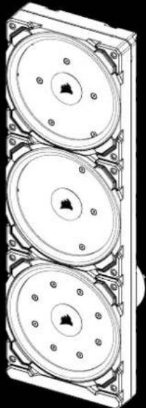
Technical line drawing of a three-tier mechanical component with mounting flanges (no text or symbols)XD7 RGB
Distro Plate/Pump Combo
HYDRO>〈SERIES

CORSAIR
ENGLISH....1
FRANÇAIS....9
DEUTSCH 17
ITALIANO 25
ESPAÑOL....33
РУССКИЙ......41
IMPORTANT NOTICE
Quick Start Guide is a general installation guide and does not cover the specifics of individual case or radiator mounting.
CORSAIR recommends you thoroughly leak-test your custom cooling system for at least 24 hours to ensure that the system is securely sealed and operating reliably. CORSAIR warranty does not cover any hardware damage resulting from poorly executed, improper and otherwise hasty assembly of your custom water-cooling system.
Disassembly of CORSAIR HYDRO X products is highly discouraged due to complex design of components. Such action may result in irreparable mechanical, electrical or chemical damage that may void the warranty. For an exact and up-to-date product compatibility list, please refer to CORSAIR website.
PACKAGE CONTENTS
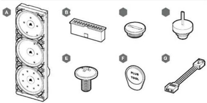
A-x1 XD7 RGB DISTRO PLATE / PUMP UNIT
B - x1 ATX 24-PIN PSU JUMPER BRIDGE
C - x4 CORSAIR G1/4" PLUGS
D — x1 CORSAIR G1/4" TEMPERATURE SENSOR PLUG
E - x12 M4 x 8mm SCREW
F - x1 PLUG TOOL
G — x1 ARGB MOTHERBOARD ADAPTER CABLE
PREREQUISITES (NOT INCLUDED)
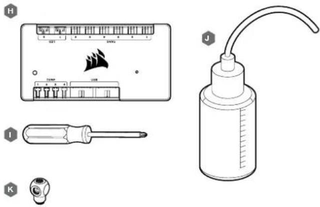
H — CORSAIR ICUE COMMANDER PRO SMART RGB LIGHTING AND FAN SPEED CONTROLLER
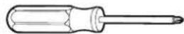
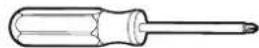
I - PHILLIPS-HEAD SCREWDRIVER
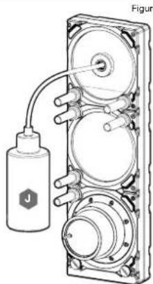
J - FILLING FLASK & CORSAIR XL TYPE COOLANT
K - CORSAIR XF ROTARY Y-SPLITTER
Note: CORSAIR iCUE Commander PRO or CORSAIR Lighting Node PRO are required for driving and controlling the RGB LED illumination. CORSAIR iCUE Commander PRO is required for automatic control of the pump and for monitoring the liquid temperature using iCUE software suite.
ENGLISH
MOUNTING THE XD7 RGB TO A CASE FRONT FAN TRAY
Secure the XD7 RGB (A) onto the case front fan tray. Use the enclosed M4 x 8mm screws (E).
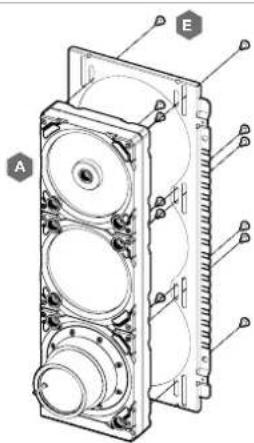
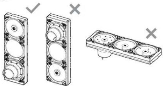
XD7 RGB MOUNTING ORIENTATION
It is mandatory to install XD7 RGB vertically with pump on the bottom side as shown on the picture. Use of other horizontal orientation is highly discouraged as it may result in recirculation of air and subsequent pump failure.
natural_image
Technical illustration of three mechanical components with circular features and mounting holes, shown without any text or symbols.3
FINALIZING THE SETUP
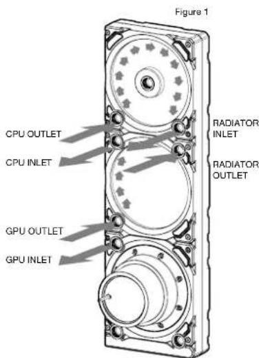
For combined CPU & GPU water cooling please follow these recommended installation steps and port configuration:
- Locate the correct ports. It is mandatory to use the correct ports, as marked on the picture (see Figure 1).
- Install the six (6) appropriate CORSAIR XF G1/4 BSPP threaded-type fittings (not included) into the appropriate distro plate ports and tighten them by hand as shown in Figure 2. Do not use any tools (i.e. pliers).
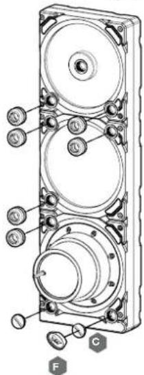
- Close the remaining open (unused) ports with the included CORSAIR G1/4 plugs (C) and tighten them using a Plug Tool (F). Refrain from using a screwdriver as it may result in damage to the surface of the plugs!
Note: The bottom most two G1/4 ports shall only be used as drain ports!
4
Figure 2
ENGLISH
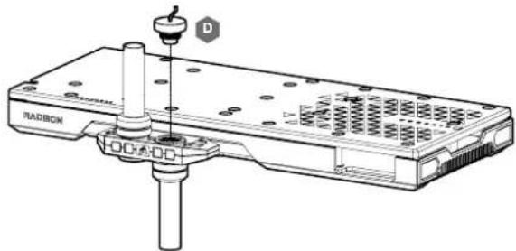
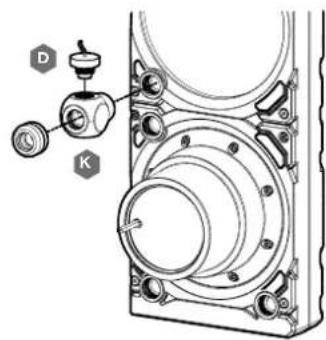
INSTALLING TEMPERATURE SENSOR PLUG
Install the enclosed CORSAIR G1/4" Temperature Sensor Plug (D) into one of the two unused G1/4" port located on the GPU water block.
INSTALLING TEMPERATURE SENSOR PLUG ON Y-SPLITTER (OPTIONALLY)
Install the enclosed CORSAIR G1/4" Temperature Sensor Plug (D) with the CORSAIR XF Rotary Y-Splitter to any INLET/OUTLET port on the XD7 other than FILL or DRAIN ports!
natural_image
Technical line drawing of a mechanical assembly with labeled components (D, K) and no readable text or symbols.5
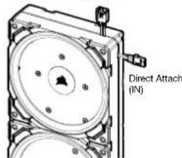
CONNECTING THE PUMP AND USING THE INTEGRATED DIGITAL RGB ILLUMINATION
A CORSAIR iCUE Commander PRO or Lighting Node PRO (either) is required in order to use the integrated RGB illumination on the XD7 RGB. CORSAIR iCUE software is used to program the visual effects. CORSAIR iCUE Commander PRO is required for automatic control of the pump and for monitoring the liquid temperature using iCUE software suite.
The XD7 RGB Distro Plate / Pump Unit can be connected to the appropriate CORSAIR controller either directly or "daisy"-chained with other CORSAIR addressable RGB component(s).
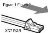
- Identify the correct RGB connector on the reservoir-pump unit (Figure 1).
- Insert the RGB connector in a CORSAIR iCUE Commander PRO port or Lighting Node PRO port (Figure 2).
- Download and install CORSAIR iCUE software suite from the following website: https://www.corsair.com/icue. Configure visual and lighting effects by following the manual for iCUE software.
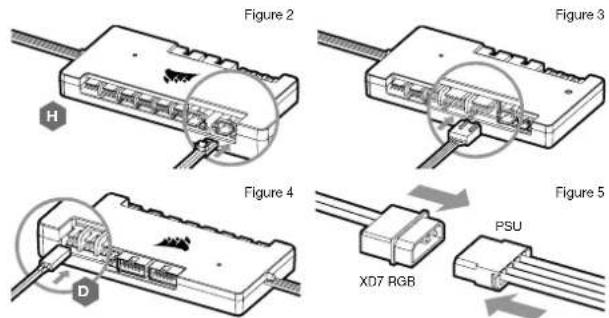
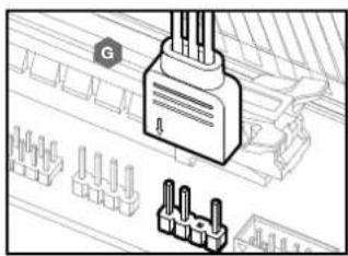
- Connect the XD7 RGB's pump 4-pin fan connector into Fan Port #6 on your CORSAIR ICUE Commander PRO (Figure 3).
- Connect the XD7 RGB's temperature sensor into temperature Port #1 on your CORSAIR iCUE Commander PRO (Figure 4).
- Connect the XD7 RGB's main power cable by plugging in a 4-pin Molex connector from your power supply (Figure 5).
Figure 1
Daisy Chain (to NEXT)
6
6
ENGLISH
CONNECTING THE XD7 RGB LIGHTING TO THE MOTHERBOARD
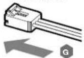
- Connect the XD7 RGB male connector into the RGB ADAPTER CABLE (G) female connector (Figure 1).
- Connect the RGB ADAPTER CABLE female connector into the Digital RGB header on the motherboard. Make sure the arrow on the RGB ADAPTER CABLE is plugged into +5V on the motherboard (Figure 2).
By using the motherboard adapter it is not possible to control the RGB illumination with iCUE software.
ARGB MOTHERBOARD
ADAPTER CABLE
natural_image
Diagram of a connector with pins and wiring, showing a terminal block and terminal blocks (no text or symbols present)FILLING AND PRIMING THE XD7 RGB
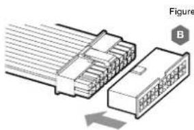
- Disconnect PSU power cables from all computer components except the XD7 RGB 4-pin Molex power connector. Make sure the PSU is turned OFF, either at the plug socket, or via the toggle switch on the rear of the PSU. Connect the enclosed ATX 24-pin PSU Jumper Bridge starter to your PSU 24-pin ATX cable. This will allow you to power on your XD7 RGB without powering on the PC (Figure 1).
- Disconnect the XD7 RGB's pump 4-pin fan connector. This will allow the pump to run at full power, allowing for easier priming and bleeding of air.
natural_image
Diagram of a connector with two connectors and a pinout, showing internal structure (no text or symbols)7
Figure 2

natural_image
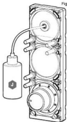
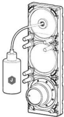
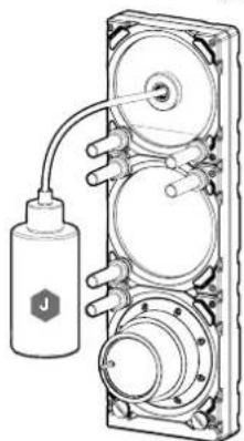
Technical illustration of a mechanical device with hoses and a labeled component (no text or symbols present)- Fill the reservoir through the top G1/4 opening with CORSAIR XL5 coolant using a filling flask to about 4cm (1/6') below opening (Figure 2).
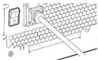
- Tum on the power by flipping the ON switch on the PSU. The pump motor will be primed with coolant from the reservoir and will start flowing through the system. Tum the power OFF before the reservoir is emptied. Do not let the pump run dry or without coolant in the reservoir as this will damage the pump (Figure 3)!
- Repeat steps 2 and 3 until your custom cooling system is full. CORSAIR recommends not to fill the reservoir more than about 4cm (1.5") from the top.
- Once the system is filled with coolant, CORSAIR recommends running it for 24 hours to remove any air trapped in the components and to make sure there are no leaks in the system. Once you have thoroughly leak-tested the system, turn OFF the PSU and disconnect ATX 24-pin PSU Jumper Bridge. Reconnect the power to other computer peripherals and start the computer.
FAQ
- Can I use the XD7 RGB as a standalone part?
No, this is a water-cooling pump with integrated reservoir which requires a complete custom water-cooling system, including cold plates (water blocks) and radiator. For more information, please visit corsair.com. - Can I use the XD7 RGB with aluminium water-cooling equipment?
No, you cannot. Certain parts are made from copper and brass and should not be mixed with aluminium. - Can I connect the RGB header directly to my motherboard?
Yes you can - using the included RGB ADAPTER CABLE (G). See page 7 - CONNECTING THE XD7 RGB LIGHTING TO THE MOTHERBOARD - Can the XD7 RGB pump be controlled without the use of CORSAIR iCUE Commander PRO?
While it is possible to use XD7 RGB without a CORSAIR iCUE Commander PRO, doing so will remove the automated pump speed control in CORSAIR iCUE software. The pump speed may be manually controlled by motherboard UEFI when XD7 RGB's 4-pin fan PWM connector is connected. - How many RGB devices can I daisy-chain to a single channel on a CORSAIR controller?
CORSAIR recommends you connect no more than three (3) Hydro X Series RGB devices of any type connected in a series on a single channel. However, you can connect one (1) XC7/XC9 water block, one (1) XG7 RGB water blocks and one (1) XD7 RGB pump unit for a total of three (3) devices. Do not mix CORSAIR fans or RGB LED strips and CORSAIR HYDRO X products on the same channel on the controller. Use a dedicated channel for other components.
8
ENGLISH
Figure 3
AVIS IMPORTANT
natural_image
Line drawing of a laboratory bottle with a curved tube and scale markings (no text or symbols)1
K

H — CONTRÔLEUR DE VITESSE DU VENTILATEUR ET DE LA LAMPE INTELLIGENTE RGB CORSAIR
ICUE COMMANDER PRO
I - TOURNEVIS CRUCIFORME PHILLIPS
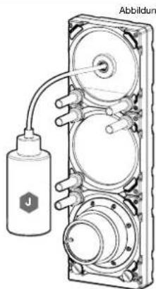
J - FLACON DE REMPLISSAGE ET LIQUIDE DE REFROIDISSEMENT TYPE XL CORSAIR
k - RÉPARTITEUR EN Y ROTATIF CORSAIR XF
natural_image
Technical illustration of three mechanical components with circular housing and mounting holes, shown without any text or symbols.FINALISATION DE LA CONFIGURATION
FRANÇAIS
INSTALLATION DE LA FICHE DU CAPTEUR DE TEMPÉRATURE
natural_image
Technical line drawing of a mechanical assembly with labeled components (D and K), no readable text or symbols present.13 14
RACCORDEMENT DE LA POMPE ET UTILIZATION DE L'ÉCLAIRAGE DIGITAL RGB INTÉGRÉ
REMLISSAGEET AMORÇAGE DU XD7 RGB
natural_image
Diagram of a connector with multiple pins, showing internal structure and an arrow indicating direction (no text or symbols)15 16
natural_image
Technical line drawing of a mechanical device with a bottle and connecting tubing (no text or symbols)Figure 2
Figure 3
WICHTIGER HINWEIS
A - x1 XD7 RGB VERTEILLERPLATE MIT PUMPE
B - x1 24-PIN-NETZTEILBRÜCKE ATX
C - x4 CORSAIR G1/4"VERSCHLUSSSTOPFEN
D - x1 CORSAIR G1/4" TEMPERATURSENSOR-STECKER
E - x12 M4 x 8mm SCHRAUBE
F—x1VERSCHLUSSSTOPFENWERKZEUG
G - x1 ARGB MAINBOARD ADAPTERKABEL
natural_image
Line drawing of a laboratory bottle with a curved tube and scale markings (no text or symbols)1
K

H — STEUERUNG DER BELEUCHTUNG UND LÜFTERGESCHWINDIGKEIT CORSAIR ICUE COMMANDER PRO SMART RGB
I - PHILLIPS-KREUZSCHLITZ-SCHRAUBENDREHER
J - FÜLLFLASCHE UND KÜHLMITTEL CORSAIR TYP XL
K - Y-VERTEILER CORSAIR XF ROTARY
natural_image
Technical illustration of three mechanical components with circular housing and mounting holes, shown without any text or symbols.19 20
DEUTSCH
INSTALLIEREN DES TEMPERATURSENSOR-STECKERS
natural_image
Technical line drawing of a RADCON device with a screw and mounting bracket (no text or symbols)INSTALLIEREN DES TEMPERATURSENSOR-STECKERS AN DEN Y-VERTEILER (OPTIONAL)
2122
natural_image
Diagram of a connector with pins and connectors, no text or symbols presentnatural_image
Diagram of a connector assembly showing two connected components with no visible text or symbols23 24
natural_image
Technical line drawing of a mechanical device with a bottle and connecting tubing (no text or symbols)Abbildung 2
natural_image
Technical illustration of three mechanical components with mounting holes and mounting holes, shown without any text or symbols.MONTAGGIO DELLA PRESA DEL SENSORE DI TEMPERATURA
29 30
natural_image
Diagram of a connector with multiple pins, showing internal structure and an arrow indicating direction (no text or symbols)3132
natural_image
Technical diagram of a mechanical device with labeled component J, showing internal components and wiring (no text or symbols beyond label)Figura 2
natural_image
Diagram of a hexagonal grid structure with a pipe inserted, showing electrical connections (no text or symbols)Figura 3
AVISO IMPORTANTE
natural_image
Technical illustration of three mechanical components with circular housing and mounting holes, shown with checkmarks (no text or symbols)35 36
CÓMO TERMINAR EL MONTAJE
ESPAÑOL
natural_image
Technical line drawing of a RADCON device with a screw and mounting bracket (no text or symbols)37 38
natural_image
Diagram of a connector with pins and wiring, showing a plug and terminal blocks (no text or symbols)natural_image
Diagram of a connector with two connectors and a pin, showing internal structure (no text or symbols)39 40
Figura 2
natural_image
Technical line drawing of a mechanical device with a labeled component (no text or symbols present)natural_image
Diagram of a hexagonal grid structure connected to a wall-mounted power outlet (no text or symbols)Figura 3
ВАЖНАЯ ИНФОРМАЦИЯ
natural_image
Technical illustration of three mechanical components with mounting holes and mounting holes, shown without any text or symbols.43 44
45 46
natural_image
Diagram of a connector with internal structure and directional arrow (no text or symbols)47 48
natural_image
Technical line drawing of a mechanical device with hoses and a labeled component (no text or symbols present)рис. 2
natural_image
Diagram of a hexagonal grid structure connected to a wall-mounted power outlet (no text or symbols)
CORSAIR Memory, Inc. encourages customers to recycle used electronic hardware and rechargeable batteries in accordance with local laws and regulations.
EN NOTE ON ENVIRONMENTAL PROTECTION After the implementation of the European Directive 2012/19/CU in the national legal system, the following apolies: - Electrical and electronic devices may not be disposed of with domestic waste. - Consumers are obligated by law to return electrical and electronic devices at the end of their service lives to the public collecting points set up for this purpose of point or sale. Details to this are defined by the national law of the respective country. The symbol on the product, the instruction manual or the package indicates that a product is subject to these regulations. By recycling, reusing the materials or other forms of utilizing and devices, you are making an important contribution to protecting our environment.
This device complies with Part 15 of the FCC Rules. Operation is subject to the following two conditions: (1) This device may not cause harmful interference, and (2) this device must accept any interference received, including interference that may cause undesired operation.
This equipment has been tested and found to comply with the limits for a Class B digital device, pursuant to Part 1b of the FCC Rules. These limits are designed to provide reasonable protection against harmful interference in a residential installation. This equipment generates, uses and can radiate radio frequency energy and, if not installed and used in accordance with the instructions, may cause harmful interference to radio communications. However, there is no guarantee that interference will not occur in a particular installation. This equipment does cause harmful interference to radio or television reception, which can be determined by turning the equipment off and on, the user is encouraged to try to correct the interference by one of the following measures: - Reorient or relocate the receiving antenna. - Increase the separation between the equipment and receiver. Connect the equipment into an outlet on a circuit different from that to which the receiver is connected. - Consult the dealer or an experienced radio/TV technician to help.
FOO Caution: Any changes or modifications not expressly approved by the party responsible for compliance could void the user's authority to operate this equipment.
EN This Class B digital apparatus meets all requirements of the Canadian interference-Causing Equipment Regulations. CAN ICES-3(BV/NMR-6(B)
EN COPSAH MEMORY, Inc. declares that this equipment is in compliance with Directive 2014/30/EU and Directive 2011/65/EU. A copy of the original declaration of conformity can be obtained at "porsar.com/documentation". Operating Temperature: 0^ C - 140^ C
- CORSAIR
- IMPORTANT NOTICE
- MOUNTING THE XD7 RGB TO A CASE FRONT FAN TRAY
- XD7 RGB MOUNTING ORIENTATION
- FINALIZING THE SETUP
- INSTALLING TEMPERATURE SENSOR PLUG
- INSTALLING TEMPERATURE SENSOR PLUG ON Y-SPLITTER (OPTIONALLY)
- CONNECTING THE PUMP AND USING THE INTEGRATED DIGITAL RGB ILLUMINATION
- CONNECTING THE XD7 RGB LIGHTING TO THE MOTHERBOARD
- FILLING AND PRIMING THE XD7 RGB
- FAQ
- AVIS IMPORTANT
- FINALISATION DE LA CONFIGURATION
- INSTALLATION DE LA FICHE DU CAPTEUR DE TEMPÉRATURE
- RACCORDEMENT DE LA POMPE ET UTILIZATION DE L'ÉCLAIRAGE DIGITAL RGB INTÉGRÉ
- REMLISSAGEET AMORÇAGE DU XD7 RGB
- WICHTIGER HINWEIS
- INSTALLIEREN DES TEMPERATURSENSOR-STECKERS
- INSTALLIEREN DES TEMPERATURSENSOR-STECKERS AN DEN Y-VERTEILER (OPTIONAL)
- MONTAGGIO DELLA PRESA DEL SENSORE DI TEMPERATURA
- AVISO IMPORTANTE
- CÓMO TERMINAR EL MONTAJE
- ВАЖНАЯ ИНФОРМАЦИЯ
Brand : CORSAIR
Model : XD7 RGB
Category : Computer cooling system