
Hydro XC9 RGB - Computer cooling system CORSAIR - Free user manual and instructions
Find the device manual for free Hydro XC9 RGB CORSAIR in PDF.
| Product Type | Water Pump/Reservoir with RGB Lighting |
| Brand | Corsair |
| Model | Hydro XC9 RGB (XD3 RGB) |
| Dimensions (approx.) | 88 mm x 55 mm (base), height 60 mm |
| Weight (approx.) | 300 g |
| Power Supply | 12 V via 4-pin Molex connector |
| Power Consumption | ≤ 10 W |
| Pump Flow Rate | Not specified, recommended with radiator and blocks |
| Materials | Copper, brass, plastic |
| Connectors | G1/4" inlet/outlet, G1/4" temperature sensor, 3-pin RGB connector |
| Lighting | Addressable RGB, iCUE compatible (requires Commander PRO or Lighting Node PRO) |
| Pump Control | 4-pin PWM, via iCUE Commander PRO or motherboard |
| Compatibility | Custom water cooling loops (copper/brass) |
| Operating Temperature | 0 °C to +40 °C |
| Installation | Vertical mounting on perpendicular bracket or 120/140 mm fan plate |
| Package Contents | XD3 RGB pump/reservoir, bracket, plates, plugs, tool, RGB adapter cable |
| Maintenance | 24-hour leak test before use, bleeding air, filling with XL5 liquid |
| Safety | Do not run pump dry, do not use with aluminum, disassembly prohibited |
| Warranty | Manufacturer's warranty (excluding damages from incorrect installation) |
| Spare Parts | Available at corsair.com (seals, plugs, etc.) |
| Repairability | Not user repairable, disassembly not recommended |
Frequently Asked Questions - Hydro XC9 RGB CORSAIR
User questions about Hydro XC9 RGB CORSAIR
0 question about this device. Answer the ones you know or ask your own.
Ask a new question about this device
Download the instructions for your Computer cooling system in PDF format for free! Find your manual Hydro XC9 RGB - CORSAIR and take your electronic device back in hand. On this page are published all the documents necessary for the use of your device. Hydro XC9 RGB by CORSAIR.
USER MANUAL Hydro XC9 RGB CORSAIR
BLOG: corsair.com/blog
FORUM: forum.corsair.com
YOUTUBE: youtube.com/corsairhowto
© 2019 - 2020 CORSAIR MEMORY Inc. All rights reserved. CORSAIR and the sails logo are registered trademarks in the United States and/or other countries. All other trademarks are the property of their respective owners. Product may vary slightly from those pictured. 49-002027 AB


CORSAIR

CUE
natural_image
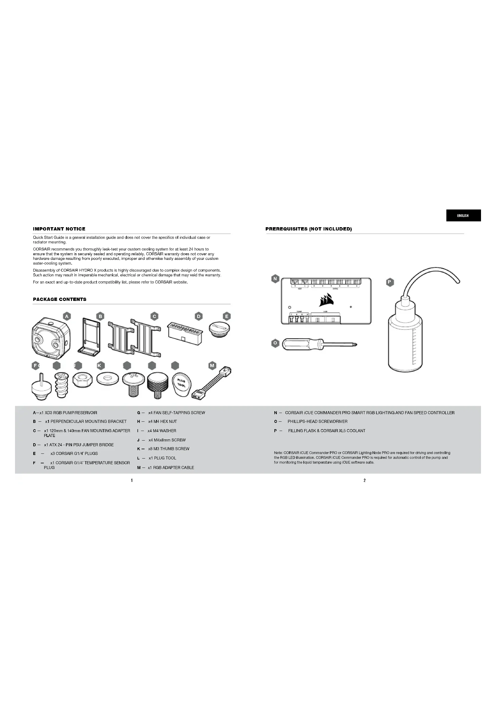
Technical line drawing of a mechanical housing component (no text or symbols)XD3 RGB
Pump/Reservoir Combo
HYDRO>〈SERIES

CORSAIR
ENGLISH....1
FRANÇAIS....11
DEUTSCH 21
ITALIANO 31
ESPAÑOL....41
РУССКИЙ 51
IMPORTANT NOTICE
Quick Start Guide is a general installation guide and does not cover the specifics of individual case or radiator mounting.
CORSAIR recommends you thoroughly leak-test your custom cooling system for at least 24 hours to ensure that the system is securely sealed and operating reliably. CORSAIR warranty does not cover any hardware damage resulting from poorly executed, improper and otherwise hasty assembly of your custom water-cooling system.
Disassembly of CORSAIR HYDRO X products is highly discouraged due to complex design of components. Such action may result in irreparable mechanical, electrical or chemical damage that may void the warranty. For an exact and up-to-date product compatibility list, please refer to CORSAIR website.
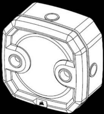
PACKAGE CONTENTS
A—x1 XD3 RGB PUMP/RESERVOIR
B - x1 PERPENDICULAR MOUNTING BRACKET
C — x1 120mm & 140mm FAN MOUNTING ADAPTER PLATE
D — x1 ATX 24 - PIN PSU JUMPER BRIDGE
E — x3 CORSAIR G1/4" PLUGS
F - x1 CORSAIR G1/4" TEMPERATURE SENSOR PLUG
G — x4 FAN SELF-TAPPING SCREW
H - x4 M4 HEX NUT
I - x4 M4 WASHER
J - x4 M4x8mm SCREW
K - x8 M3 THUMB SCREW
L - x1 PLUG TOOL
M - x1 RGB ADAPTER CABLE
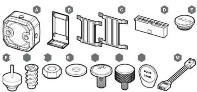
PREREQUISITES (NOT INCLUDED)
N — CORSAIR iCUE COMMANDER PRO SMART RGB LIGHTING AND FAN SPEED CONTROLLER
O — PHILLIPS-HEAD SCREWDRIVER
P — FILLING FLASK & CORSAIR XL5 COOLANT
Note: CORSAIR iCUE Commander PRO or CORSAIR Lighting Node PRO are required for driving and controlling the RGB LED illumination. CORSAIR iCUE Commander PRO is required for automatic control of the pump and for monitoring the liquid temperature using iCUE software suite.
ENGLISH
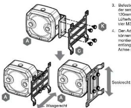
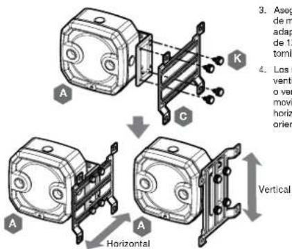
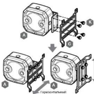
MOUNTING THE XD3 RGB TO PERPENDICULAR MOUNTING BRACKET
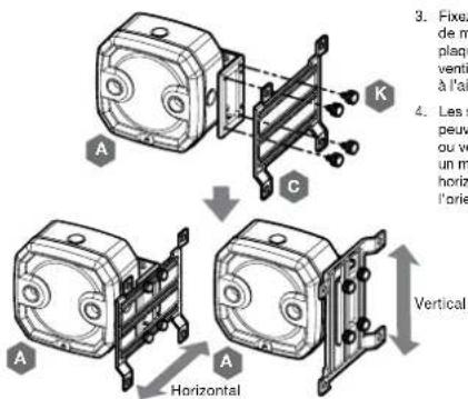
- Secure the Perpendicular mounting bracket (B) to the XD3 RGB (A) using four (4) M3 thumb screws (K).
- The Perpendicular mounting bracket can be oriented in two ways and allows free movement along the horizontal axis.
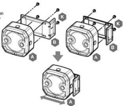
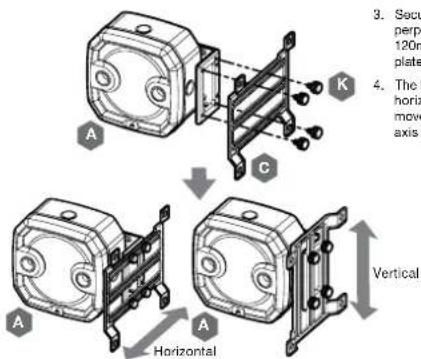
- Secure the XD3 RGB (A) with the perpendicular mounting bracket onto a 120mm or 140mm fan mounting adapter plate (C) using four M3 thumb screws (K).
- The fan adapter brackets can be mounted horizontally or vertically thus allowing free movement along the horizontal or vertical axis (depending on orientation).
MOUNTING THE XD3 RGB TO A FAN MOUNTING ADAPTER PLATE
- Place the XD3 RGB (A) on the 120mm or 140mm fan mounting adapter plate (C). Secure the XD3 RGB to the mounting adapter plate using four M3 thumb screws (K).
- The fan adapter brackets can be mounted horizontally thus allowing free movement along the horizontal axis.
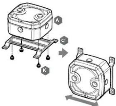
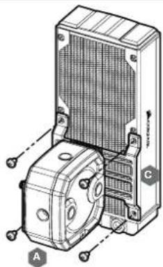
MOUNTING THE XD3 RGB TO A CORSAIR XR RADIATOR
Secure the XD3 RGB (A) with the preinstalled 120mm or 140mm fan mounting adapter plate (C) to the CORSAIR XR radiator with the short 6mm (0.25") M4XP0.7 screws supplied with the CORSAIR XR radiator itself.
natural_image
Technical line drawing of a mechanical device with labeled components A and C (no text or symbols beyond labels)ENGLISH
MOUNTING THE XD3 RGB TO A CASE FAN
Secure the XD3 RGB (A) with the preinstalled 120mm or 140mm fan mounting adapter plate (C) to a fan using four enclosed self-tapping fan screws (G).
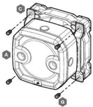
MOUNTING THE XD3 RGB DIRECTLY TO A CASE FAN SLOT
Secure the XD3 RGB (A) with the preinstalled 120mm or 140mm fan mounting adapter plate (C) onto a case fan opening. Use the enclosed M4x8mm screws (J) along with washers (I) and M4 hex nuts (H).
5
MOUNTING THE XD3 RGB DIRECTLY TO A CASE FAN SLOT
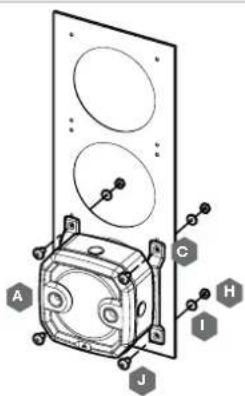
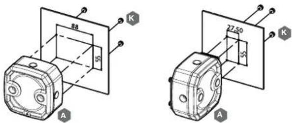
Locate the suitable cut-out hole pattern in the chassis that would fit 88mm x 65mm hole pattern (if mounting the XD3 RGB directly) or 27.5mm x 55mm if using the perpendicular mounting bracket. If there are no hole patterns available, there is an option to drill the holes using a ∅3,4mm - ∅4mm drill bit. Secure the unit by screwing four M3 thumb screws (K).
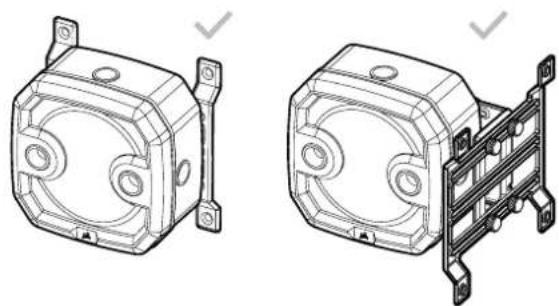
XD3 RGB MOUNTING ORIENTATION
The XD3 RGB must be installed vertically (see picture below).
natural_image
Technical line drawings of two mechanical components: a front view and a side-view assembly (no text or symbols)6
ENGLISH
FINALIZING THE SETUP
- Install the two (2) appropriate CORSAIR XF G1/4 BSPP threaded-type fittings (not included) into the reservoir ports and tighten them by hand. Do not use any tools (i.e. pliers) (Figure 1).
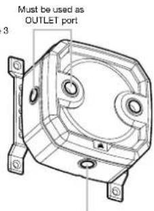
- It is mandatory to use the front-left port as the OUTLET. The recommended INLET (return) port is marked on the image below. Optionally, you can use the top G1/4 port as an INLET (return) line as well (Figure 2 and 3).
- Install the CORSAIR G1/4 Temperature Sensor Plug (F) into the G1/4 port located on the base of the unit. Do not install the temperature sensor on any of the top ports.
- Close the remaining three (3) open (unused) ports with the included CORSAIR G1/4 plugs and tighten them using a plug tool (L). Refrain from using a screwdriver as it may result in damage to the surface of the plugs.
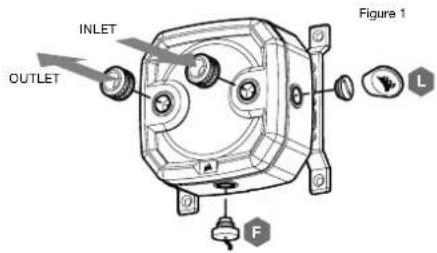
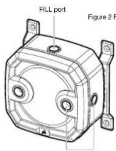
Can be used as INLET port
Temperature sensor
7
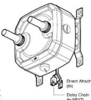
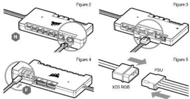
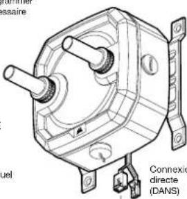
CONNECTING THE PUMP AND USING THE INTEGRATED DIGITAL RGB ILLUMINATION
A CORSAIR iCUE Commander PRO or Lighting Node PRO (either) is required in order to use the integrated RGB illumination on the XD3 RGB. CORSAIR iCUE software is used to program the visual effects. CORSAIR iCUE Commander PRO is required for automatic control of the pump and for monitoring the liquid temperature using iCUE software suite.
The XD3 RGB Pump/Reservoir can be connected to the appropriate CORSAIR controller either directly or "daisy"-chained with other CORSAIR addressable RGB component(s).
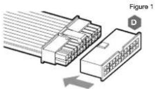
- Identify the correct RGB connector on the reservoir-pump unit (Figure 1).
- Insert the RGB connector in a CORSAIR iCUE Commander PRO port or Lighting Node PRO port (Figure 2).
- Download and install CORSAIR iCUE software suite from the following website: https://www.corsair.com/icue. Configure visual and lighting effects by following the manual for iCUE software.
- Connect the XD3 RGB's pump 4-pin fan connector into Fan Port #6 on your CORSAIR ICUE Commander PRO (Figure 3).
- Connect the XD3 RGB's temperature sensor into temperature Port #1 on your CORSAIR iCUE Commander PRO (Figure 4).
- Connect the XD3 RGB's main power cable by plugging in a 4-pin Molex connector from your power supply (Figure 5).
Figure 1
8
ENGLISH
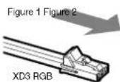
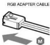
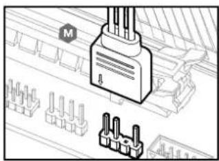
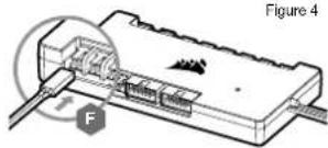
CONNECTING THE XD3 RGB LIGHTING TO THE MOTHERBOARD
- Connect the XD3 RGB male connector into the RGB ADAPTER CABLE (M) female connector (Figure 1).
- Connect the RGB ADAPTER CABLE female connector into the Digital RGB header on the motherboard. Make sure the arrow on the RGB ADAPTER CABLE is plugged into +5V on the motherboard (Figure 2).
By using the motherboard adapter it is not possible to control the RGB illumination with iCUE software.
natural_image
Diagram of a connector with pins and a labeled component (no readable text or symbols)FILLING AND PRIMING THE XD3 RGB
- Disconnect PSU power cables from all computer components except the XD3 RGB 4-pin Malex power connector. Make sure the PSU is turned OFF, either at the plug socket, or via the toggle switch on the rear of the PSU. Connect the enclosed ATX 24-pin PSU Jumper Bridge starter to your PSU 24-pin ATX cable. This will allow you to power on your XD3 RGB without powering on the PC (Figure 1).
- Disconnect the XD3 RGB's pump 4-pin fan connector. This will allow the pump to run at full power, allowing for easier priming and bleeding of air.
- Fill the reservoir through the top G1/4 opening with CORSAIR XL5 coolant using a filling flask to about 0.5cm (1/5) below the top (Figure 2).
natural_image
Diagram of a connector assembly showing two connected components with pin numbering (no text or symbols)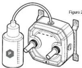
natural_image
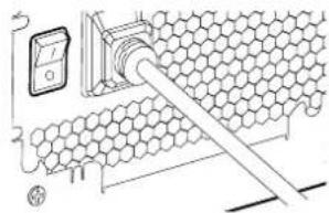
Technical line drawing of a mechanical device with a bottle and connecting rod (no text or symbols)- Turn on the power by flipping the ON switch on the PSU. The pump motor will be primed with coolant from the reservoir and will start flowing through the system. Turn the power OFF before the reservoir is emptied. Do not let the pump run dry or without coolant in the reservoir as this will damage the pump (Figure 3)!
- Repeat steps 2 and 3 until your custom cooling system is full. CORSAIR recommends not to fill the reservoir more than about 0.5cm (1/5) from the top.
- Once the system is filled with coolant, CORSAIR recommends running it for 24 hours to remove any air trapped in the components and to make sure there are no leaks in the system. Once you have thoroughly leak-tested the system, turn OFF the PSU and disconnect ATX 24-pin PSU Jumper Bridge. Reconnect the power to other computer peripherals and start the computer.
FAQ
- Can I use the XD3 RGB as a standalone part?
No, this is a water-cooling pump with integrated reservoir which requires a complete custom water-cooling system, including cold plates (water blocks) and radiator. For more information, please visit corsair.com. - Can I use the XD3 RGB with aluminium water-cooling equipment?
No, you cannot. Certain parts are made from copper and brass and should not be mixed with aluminium. - Can I connect the RGB header directly to my motherboard?
Yes you can - using the included RGB ADAPTER CABLE (M). See page 9 - CONNECTING THE XD3 RGB LIGHTING TO THE MOTHERBOARD - Can the XD3 RGB pump be controlled without the use of CORSAIR iCUE Commander PRO?
While it is possible to use XD3 RGB without a CORSAIR iCUE Commander PRO, doing so will remove the automated pump speed control in CORSAIR iCUE software. The pump speed may be manually controlled by motherboard UEFI when XD3 RGB's 4-pin fan PWM connector is connected. - How many RGB devices can I daisy-chain to a single channel on a CORSAIR controller? CORSAIR recommends you connect no more than three (3) Hydro X Series RGB devices of any type connected in a series on a single channel. However, you can connect one (1) XC7/XC9 water block, two (2) XC7 RGB water blocks and one (1) XD3 RGB pump unit for a total of four (4) devices. Do not mix CORSAIR fans or RGB LED strips and CORSAIR HYDRO X products on the same channel on the controller. Use a dedicated channel for other components.
ENGLISH
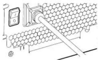
Figure 3
AVIS IMPORTANT
N — CONTRÔLEUR DE VITESSE DU VENTILATEUR ET DE LA LAMPE INTELLIGENTE RGB CORSAIR
ICUE COMMANDER PRO
0 - TOURNEVIS CRUCIFORME PHILLIPS
P — BALLON DE REMPLISSAGE ET LIQUIDE DE REFROIDISSEMENT CORSAIR XL5
MONTAGE DU XD3 RGB SUR UN CORSAIR RADIATEUR
natural_image
Technical line drawing of a mechanical assembly with labeled components A, B, and C (no text or symbols beyond labels)FRANÇAIS
MONTAGE DU XD3 RGB SUR UN CORSAIR VENTILATEUR BOÎTIER
MONTAGE DU XD3 RGB DIRECTEMENT SUR UN SLOT DE VENTILATEUR BOÎTIER
15 16
MONTAGE DU XD3 RGB DIRECTEMENT SUR LA TÔLE DU BOÎTIER
natural_image
Technical line drawings of two mechanical components with mounting brackets (no text or symbols)FRANÇAIS
FINALISATION DE L'INSTALLATION
natural_image
Technical line drawing of a mechanical housing component (no text or symbols)natural_image
Technical line drawing of a mechanical housing component (no text or symbols)natural_image
Diagram of an electronic device with labeled ports and a magnified inset showing internal components (no text or symbols present)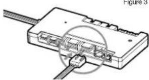
natural_image
Diagram of a USB cable connector with internal ports and cable routing (no text or labels)Figure 4
natural_image
Diagram of a mechanical device with labeled force F and Figure 4 (no readable text or symbols)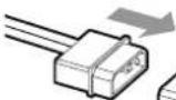
XD3 RGB
Figure 1
REMLISSAGEET AMORÇAGE DU XD3 RGB
natural_image
Diagram of a connector assembly showing two connected components with no visible text or symbols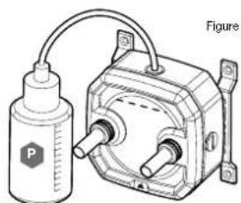
natural_image
Technical line drawing of a mechanical device with a cylindrical component and a motor housing (no text or symbols)1920
FAQ
A—x1 PUMPE/RESERVOIR XD3 RGB
E - x3 STECKER CORSAIR G1/4"
F - x1 TEMPERATURSENSOR-STECKER CORSAIR G1/4" L-x1STECKERWERKZEUG
J - x4 SCHRAUBE M4x8mm
K — x8 FINGERSCHRAUBE M3
M - x1 RGBADAPTERKABEL
MONTAGE DES XD3 RGB AN EINEN CORSAIR KÜHLER
natural_image
Technical line drawing of a mechanical device with labeled components A and C (no text or symbols beyond labels)DEUTSCH
MONTAGE DES XD3 RGB AN EINEN GEHÄUSELÜFTER
25 26
MONTAGE DES XD3 RGB DIREKT AN DAS GEHÄUSEBLECH
natural_image
Technical line drawings of two mechanical components with mounting brackets (no text or symbols)DEUTSCH
FINALISIERUNG DES SETUPS
natural_image
Diagram of a connector with pins and a labeled terminal (M), no readable text or symbols present.natural_image
Diagram of a mechanical device with a bottle and motor, no visible text or symbolsnatural_image
Diagram of a hexagonal grid structure with a pipe and a digital display unit (no text or symbols)Abbildung 3
AVVISO IMPORTANTE
E - x3 TAPPI CORSAIR G1/4"
F - x1 TAPPO SENSORE TEMPERATURA CORSAIR G1/4"
G - x4 VITE AUTOFILETTANTI PER LA VENTOLA
H - x4 DADO ESAGONALE M4
I - x4 RONDELLA M4
J - x4 VITE M4x8mm
K - x8 VITE ZIGRINATA M3
L - x1 ATTREZZO PER I TAPPI
M - x1 CAVO ADATTATORE RGB
N — CORSAIR ICUE COMMANDER PRO CONTROLLER ILLUMINAZIONE RGB E VELOCITÀ DELLA VENTOLA
O - CACCIAVITE PHILLIPS
P — FLACONCINO E LIQUIDO DI RAFFREDDAMENTO CORSAIR XL5
MONTAGGIO DELL'XD3 RGB SU UN RADIATORE
natural_image
Technical line drawing of a mechanical device with labeled components A and C (no text or symbols beyond labels)ITALIANO
MONTAGGIO DELL'XD3 RGB SU UNA VENTOLA DEL CASE
MONTAGGIO DELL'XD3 RGB DIRETTAMENTE SU UNO SLOT DELLA VENTOLA DEL CASE
35 36
MONTAGGIO DELL'XD3 RGB DIRETTAMENTE SULLA LAMIERA DEL CASE
natural_image
Technical line drawings of two mechanical housing components with mounting brackets (no text or symbols)ITALIANO
natural_image
Technical diagram showing a connector with pins and a separate terminal block (no text or symbols)Figura 1 Figura 2
RIEMPIMENTO E INNESCO DELL'XD3 RGB
natural_image
Diagram of a hexagonal grid structure with a pipe inserted, no text or symbols presentITALIANO
AVISO IMPORTANTE
MONTAJE DE XD3 RGB A UN RADIADOR
natural_image
Technical line drawing of a mechanical device with labeled components A and C (no text or symbols beyond labels)ESPAÑOL
MONTAJE DE XD3 RGB A UN VENTILADOR DE CAJA
MONTAJE DEL XD3 RGB DIRECTAMENTE EN LA RANURA DEL VENTILADOR DE CAJA
45 46
MONTAJE DEL XD3 RGB DIRECTAMENTE EN LA CAJA DE CHAPA
natural_image
Technical line drawings of two mechanical components with mounting brackets (no text or symbols)ESPAÑOL
natural_image
Technical diagram showing a connector with pins and a separate terminal block (no text or symbols)Figura 1 Figura 2
natural_image
Diagram of a connector assembly showing two connected components with no visible text or symbols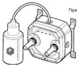
natural_image
Technical illustration of a mechanical device with a cylindrical component and a motor housing (no text or symbols)49 50
natural_image
Diagram of a honeycomb structure with a digital meter connected to a pipe (no text or symbols)Figura 3
ВАЖНАЯ ИНФОРМАЦИЯ
A - x1 HACOC/PE3EPBAYP XD3 RGB
В—х1ПЕРПЕНДИКУЛЯРНЫЙ МОНТАЖНЫЙ КРОНШТЕЙН
natural_image
Technical line drawing of a mechanical device with labeled components A and C (no text or symbols beyond labels)РУССКИЙ
55 56
natural_image
Technical line drawings of two mechanical components with mounting brackets (no text or symbols)РУССКИЙ
ЗАВЕРШЕНИЕ НАСТРОЙКИ
РУССКИЙ
natural_image
Technical diagram showing a connector with pins and a labeled M (no text or symbols beyond basic labels)Рис. 1 Рис. 2
natural_image
Diagram of a connector with multiple pins, showing internal structure and an arrow indicating direction (no text or symbols present)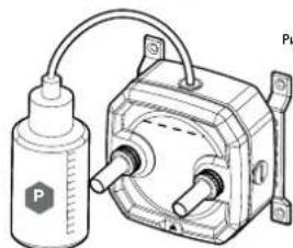
natural_image
Technical line drawing of a mechanical device with a cylindrical component and a motor housing (no text or symbols)59 60
Рис.3
natural_image
Diagram of a hexagonal grid structure with a pipe inserted, no text or symbols presentAfter the implementation of the European Directive 2012/19/CU in the national legal system, the following applies:
- Electrica and electronic devices may not be disposed of with domestic waste. - Consumers are obligated by law to return electrical and electronic devices at the end of their service lives to the public collecting points set up for this purpose of print or sale. Details to this are defined by the national law of the respective country. The symbol on the product, the instruction manual or the package indicates that a product is subject to these regulations. By recycling, reusing the materials or other forms of utilizing and devices, you are making an important contribution to protecting our environment.
FR REMARQUE CONCERNANT LA PROTECTION DE L'ENVIRONNEMENT
This device complies with Part 15 of the FCC Rules. Operation is subject to the following two conditions: (1) This device may not cause harmful interference, and (2) this device must accept any interference received, including interference that may cause undesired operation.
This equipment has been tested and found to comply with the limits for a Class B digital device, pursuant to Part 16 of the FCC Rules. These limits are designed to provide reasonable protection against harmful interference in a residential installation. This equipment generates, uses and can radiate radio frequency energy and, if not installed and used in accordance with the instructions, may cause harmful interference to radio communications. However, there is no guarantee that interference will not occur in a particular installation. This equipment does cause harmful interference to radio or television reception, which can be determined by turning the equipment off and on, the user is encouraged to try to correct the interference by one of the following measures: - Recent or relocate the receiving antenna. - Increase the separation between the equipment and receiver. - Connect the equipment into an outlet on a circuit different from that to which the receiver is connected. - Consult the dealer or an experienced radio/TV technician for help.
FCC Caution: Any changes or modifications not expressly approved by the party responsible for compliance could void the user's authority to operate this equipment.
EN This Class B digital acogalus meets all requirements of the Canadian interference-Causing Equipment Regulations. CAN ICES-3(BV/NMR-3(E))
EN CORSAIN MEMORY, Inc. declares that this equipment is in compliance with Directive 2014/30/EU and Directive 2011/85/EU. A copy of the original declaration of conformity can be obtained at "corsain.com/documentation". Operating Temperature: 0°C - +40°C
- CORSAIR
- XD3 RGB
- IMPORTANT NOTICE
- MOUNTING THE XD3 RGB TO PERPENDICULAR MOUNTING BRACKET
- MOUNTING THE XD3 RGB TO A FAN MOUNTING ADAPTER PLATE
- MOUNTING THE XD3 RGB TO A CORSAIR XR RADIATOR
- MOUNTING THE XD3 RGB TO A CASE FAN
- MOUNTING THE XD3 RGB DIRECTLY TO A CASE FAN SLOT
- XD3 RGB MOUNTING ORIENTATION
- FINALIZING THE SETUP
- CONNECTING THE PUMP AND USING THE INTEGRATED DIGITAL RGB ILLUMINATION
- CONNECTING THE XD3 RGB LIGHTING TO THE MOTHERBOARD
- FILLING AND PRIMING THE XD3 RGB
- FAQ
- AVIS IMPORTANT
- MONTAGE DU XD3 RGB SUR UN CORSAIR RADIATEUR
- MONTAGE DU XD3 RGB SUR UN CORSAIR VENTILATEUR BOÎTIER
- MONTAGE DU XD3 RGB DIRECTEMENT SUR UN SLOT DE VENTILATEUR BOÎTIER
- MONTAGE DU XD3 RGB DIRECTEMENT SUR LA TÔLE DU BOÎTIER
- FINALISATION DE L'INSTALLATION
- REMLISSAGEET AMORÇAGE DU XD3 RGB
- MONTAGE DES XD3 RGB AN EINEN CORSAIR KÜHLER
- MONTAGE DES XD3 RGB AN EINEN GEHÄUSELÜFTER
- MONTAGE DES XD3 RGB DIREKT AN DAS GEHÄUSEBLECH
- FINALISIERUNG DES SETUPS
- AVVISO IMPORTANTE
- MONTAGGIO DELL'XD3 RGB SU UN RADIATORE
- MONTAGGIO DELL'XD3 RGB SU UNA VENTOLA DEL CASE
- MONTAGGIO DELL'XD3 RGB DIRETTAMENTE SU UNO SLOT DELLA VENTOLA DEL CASE
- MONTAGGIO DELL'XD3 RGB DIRETTAMENTE SULLA LAMIERA DEL CASE
- RIEMPIMENTO E INNESCO DELL'XD3 RGB
- AVISO IMPORTANTE
- MONTAJE DE XD3 RGB A UN RADIADOR
- MONTAJE DE XD3 RGB A UN VENTILADOR DE CAJA
- MONTAJE DEL XD3 RGB DIRECTAMENTE EN LA RANURA DEL VENTILADOR DE CAJA
- MONTAJE DEL XD3 RGB DIRECTAMENTE EN LA CAJA DE CHAPA
- ВАЖНАЯ ИНФОРМАЦИЯ
- ЗАВЕРШЕНИЕ НАСТРОЙКИ
- FR REMARQUE CONCERNANT LA PROTECTION DE L'ENVIRONNEMENT
Brand : CORSAIR
Model : Hydro XC9 RGB
Category : Computer cooling system