SILENT DESIGN - Fan Soler & Palau - Free user manual and instructions
Find the device manual for free SILENT DESIGN Soler & Palau in PDF.
| Product type | Axial extraction fan |
| Brand | Soler & Palau |
| Model | SILENT DESIGN (SILENT-100/200/300 DESIGN) |
| Mounting hole diameter | 105 mm (SILENT-100), 125 mm (SILENT-200), 160 mm (SILENT-300) |
| Recommended duct diameter | 100 mm (SILENT-100), 125 mm (SILENT-200), 150/160 mm (SILENT-300) |
| Power supply | Single-phase, voltage and frequency as per nameplate |
| Double insulation | Class II, no earth connection |
| Available functions | Automatic (hygrostat), adjustable timer, manual operation |
| Hygrostat range (CHZ model) | 60 to 90% RH |
| Timer (CRZ model) | 1 to 30 minutes |
| Timer (CHZ model) | 2 to 20 minutes |
| Installation | Wall or ceiling, with non-return flap |
| Maintenance | Regular cleaning of the protective grille |
| Safety | Use by children over 8 years old with supervision |
| Warranty | Covers defects in materials or workmanship |
| Material | Not specified |
| Weight | Not specified |
Frequently Asked Questions - SILENT DESIGN Soler & Palau
User questions about SILENT DESIGN Soler & Palau
0 question about this device. Answer the ones you know or ask your own.
Ask a new question about this device
Download the instructions for your Fan in PDF format for free! Find your manual SILENT DESIGN - Soler & Palau and take your electronic device back in hand. On this page are published all the documents necessary for the use of your device. SILENT DESIGN by Soler & Palau.
USER MANUAL SILENT DESIGN Soler & Palau
text_image
Technical diagram of a mechanical device with numbered components, showing internal components and assembly steps.Fig.1
natural_image
Simple line drawing of a rectangular box with a small square clip on top (no text or symbols)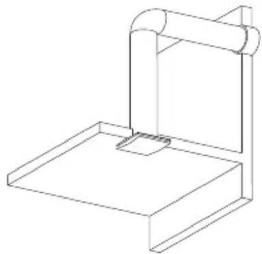
natural_image
Line drawing of a mechanical support structure with a cylindrical component and base platform (no text or symbols)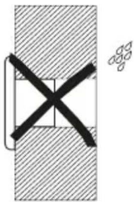
natural_image
Pure mechanical cross-section diagram without any text, numbers, or symbols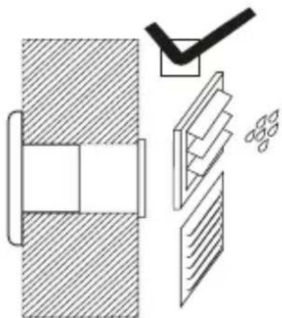
natural_image
Technical diagram showing a mechanical assembly with cross-sections and a checkmark (no text or symbols)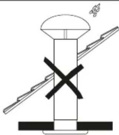
natural_image
Diagram of a mechanical assembly with a central component and two diagonal supports, no text or symbols present.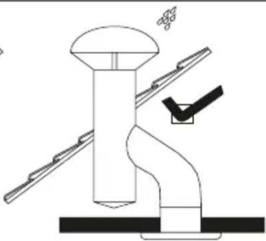
natural_image
Technical line drawing of a mechanical assembly with no visible text or symbolsFig.2
natural_image
Pure electrical circuit lines without any symbolsFig.3
natural_image
Pure electrical circuit lines without any symbolsFig.4
text_image
L N L N LsFig.5
text_image
L N L N LsFig.6
text_image
T(min)SILENTCRZ
Fig.7
Fig.8
text_image
L N L N Ls
natural_image
Diagram of a fan or vent system with labeled terminals L and N, connected to a power outlet (no text or symbols beyond labels)Fig.9
flowchart
graph TD
    A["T(min)"] --> B["+"]
    B --> C["HR(%)"]
    C --> D["+"]
    D --> E["-"]
    E --> F["+"]
    F --> G["HR(%)"]
    style A fill:#f9f,stroke:#333
    style B fill:#ccf,stroke:#333
    style C fill:#cfc,stroke:#333
    style D fill:#fcc,stroke:#333
    style E fill:#cff,stroke:#333
    style F fill:#ffc,stroke:#333
Fig.10
CT-12/14
text_image
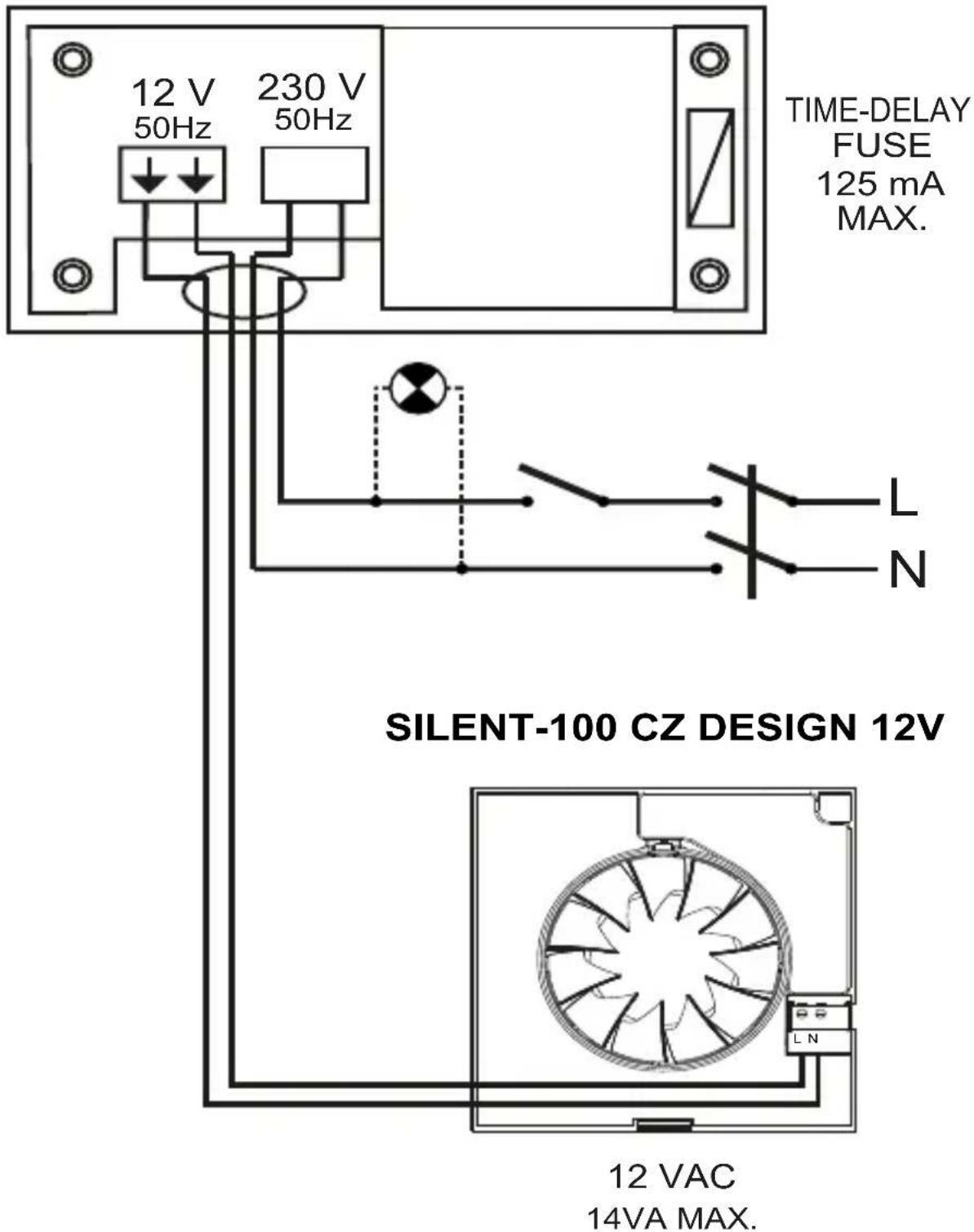
12 V 50Hz 230 V 50Hz TIME-DELAY FUSE 125 mA MAX. SILENT-100 CZ DESIGN 12V 12 VAC 14VA MAX.Fig.11
text_image
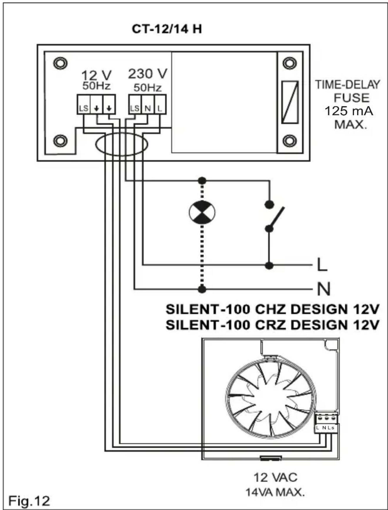
CT-12/14 H 12 V 50Hz 230 V 50Hz LS N L TIME-DELAY FUSE 125 mA MAX. SILENT-100 CHZ DESIGN 12V SILENT-100 CRZ DESIGN 12V L N 12 VAC 14VA MAX. Fig.12ESPAÑOL
Extractores helicoidales SILENT DESIGN
The SILENT DESIGN extractor fan range is manufactured to the high standards of production and quality as laid down by the international Quality Standard ISO 9001. All components have been checked and every one of the final products will have been individually tested at the end of the manufacturing process.
On receipt of the product we recommend that you to check the following:
1- That it is the correct model.
2- That the details on the rating label are those you require: voltage, frequency...
The installation must be carried out in accordance with the electrical standards in force in your country.
User instruction
This appliance can be used by children aged from 8 years and above and persons with reduced physical, sensory or mental capabilities or lack of experience and knowledge if they have been given supervision or instruction concerning use of the appliance in a safe way and understand the hazards involved. Children shall not play with the appliance. Cleaning and user maintenance shall not be made by children without supervision.
Installation
IMPORTANT: Before installing and wiring the unit, ensure that the main supply is disconnected.
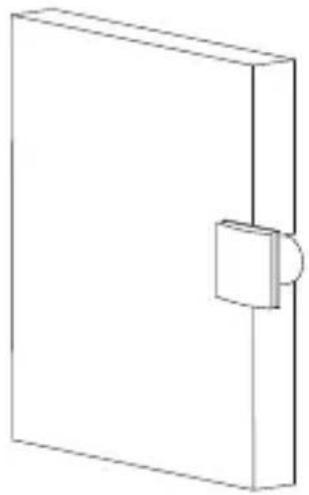
Fig. 1:
1- Protection grille
2- Connection terminals
3- Outlet with backdraught shutter
4- Cable entry
The SILENT DESIGN is suitable for wall or ceiling mounting and can either discharge directly to the outside or via an individual ducting system (see Fig.2).
The unit can be mounted on the wall or ceiling using the 4 rubber blocks and the screws provided.
Make a hole in the wall or ceiling of diameter:
- SILENT-100 DESIGN: 105 mm
- SILENT-200 DESIGN: 125 mm
- SILENT-300 DESIGN: 160 mm.
If the unit is to be installed with individual ducting, use a standard duct of diameter:
- SILENT-100 DESIGN: 100 mm
- SILENT-200 DESIGN: 125 mm
- SILENT-300 DESIGN: 150 / 160 mm.
Ensure that there are no obstructions to the airflow and that the impeller turns freely.
Fix the extractor to the wall in such a way that it is not distorted in order to avoid noise generation or problems with the rotation of the impeller. Make sure that the backdraught shutter opens freely and has not being damaged in transit. Introduce the mains cable through the cable entry (4) and fi x it to the wall.
Connect the electrical wiring as set out below and then mount the protection grille (1).
Electrical connection
The SILENT DESIGN is an extractor designed for a single phase supply, with voltage and frequency as indicated on the rating plate of the unit. The units are manufactured with double electrical insulation (Class II) and therefore they do not need an earth connection.
The electrical installation must include a double pole switch with a contact clearance of at least 3 mm.
The electrical cable must enter the SILENT DESIGN through the cable entry (4).
Once the cable has been introduced proceed using the electrical wiring diagram applicable to the selected model.
SILENT CZ DESIGN
For these models use the following diagrams:
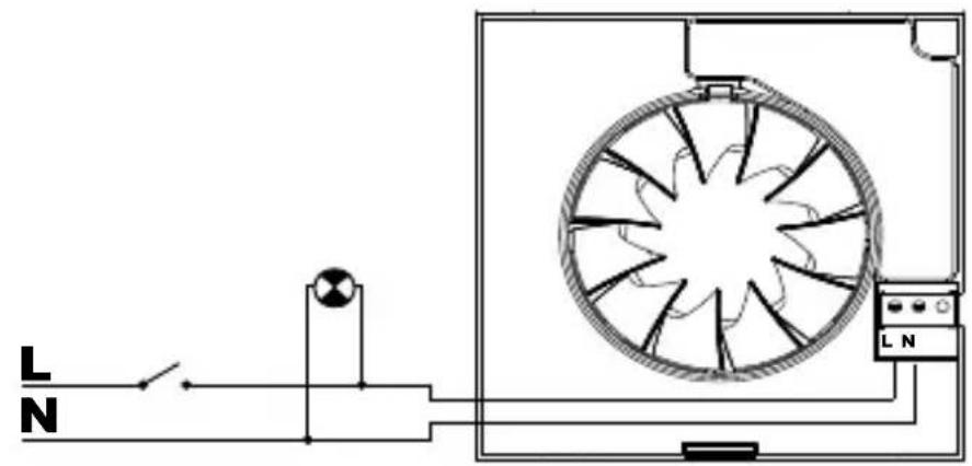
Fig.3: Switching the extractor through the light switch.
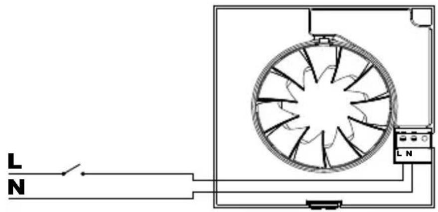
Fig.4: To switch the fan through an independent switch.
SILENT-100 CZ DESIGN 12V
For these models use the diagram fi g.11
SILENT CRZ DESIGN
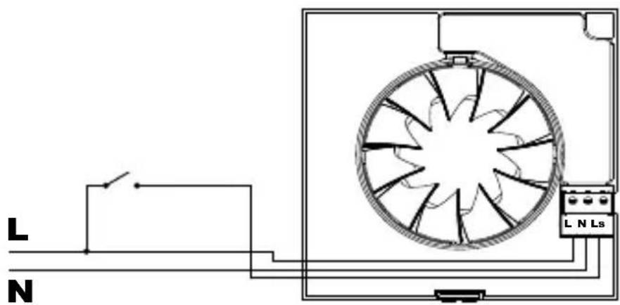
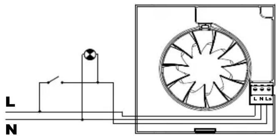
This model is provided with an adjustable over-run timer. The timer allows the fan to continue to operate for the selected period after the switch has been turned off (fi g.6).
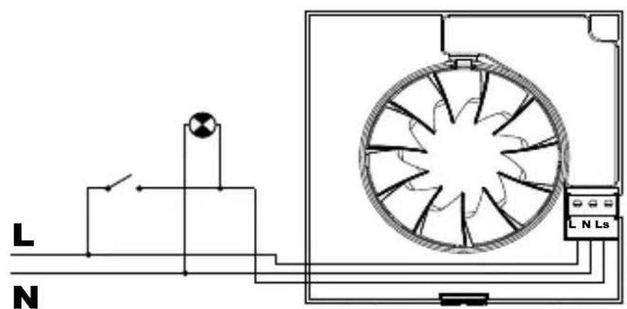
Model provided with a 4 positions adjustable electronic timer: Fig.5 shows how to connect the fan with timer utilising the same switch as for the lighting circuit.
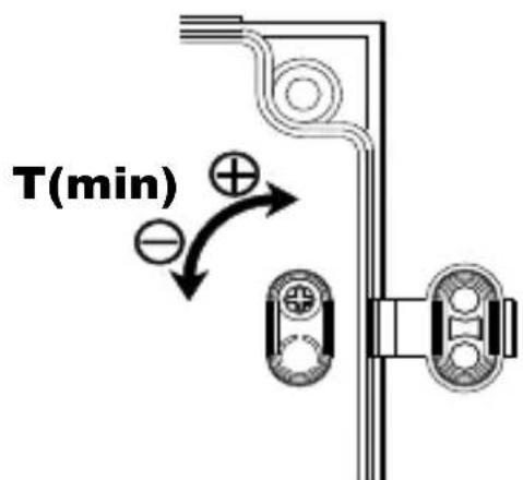
To set the timer, turn the potentiometer on the printed circuit board as (fi g.7).
- To reduce the "run on" time, turn anti-clockwise (min. 1 minute)
- To increase the "run on" time, turn clockwise (max: 30 minutes).
SILENT CHZ DESIGN
Models provided with an electronic humidistat which can be adjusted from 60% to 90% RH (relative humidity) and with a timer, adjustable between 2 and 20 minutes.
Operation
Case 1: Automatic operation (fi g.9) In automatic operation, the humidistat causes the extractor to operate automatically when the humidity level in the room is higher than the set level. The extractor will stop automatically when the humidity drops below the selected level and after the selected period set on the timer.
Case 2: Automatic operation as in case 1 with the facility to override the hygrostat by means of the light switch (fi g.8), when the humidity level in the room is lower than the selected level. In this case, the extractor continues to operate for the selected period set on the timer after the switch light has been switched off.
ATENTION: When the humidity rate is above the selected value, the automatic option takes precedence over the manual and the unit cannot then be switched off using a switch.
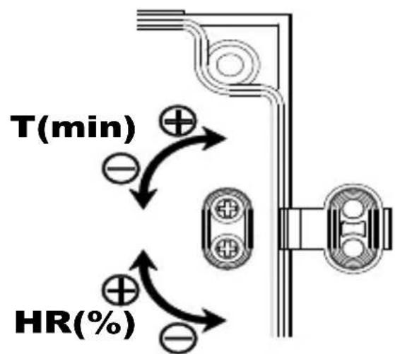
The desired humidity level is selected by means of a potentiometer “% Hr” positioned on the printed circuit board (fi g.10) and accessible once the grille (1) has been removed.
- To increase the humidity setting turn anticlockwise (min.60 %)
- To reduce the humidity setting turn clockwise (max. 90 %)
To set the timer, turn the potentiometer "t min." on the printed circuit board (fi g.10):
- To reduce the "run on" time, turn anticlockwise (min. 2 minutes)
- To increase the "run on" time, turn clockwise (max: 20 minutes).
SILENT-100 CHZ / CRZ DESIGN 12V
For these models use the diagram fi g.12
User instruction
This appliance can be used by children aged from 8 years and above and persons with reduced physical, sensory or mental capabilities or lack of experience and knowledge if they have been given supervision or instruction concerning use of the appliance in a safe way and understand the hazards involved. Children shall not play with the appliance. Cleaning and user maintenance shall not be made by children without supervision.
Maintenance
The extractor fan only requires periodical cleaning using a cloth lightly impregnated with a soft detergent.
After Sales Service
We recommend you not to try to dismantle or remove any other parts than those mentioned as any tampering would automatically cancel the S&P guarantee. If you detect any fault, contact your S&P dealer.
S&P reserves the right to alter specifications without notice
Putting out of service and recycling
EEC legislation and our consideration of future generations mean that we should always recycle materials where possible; please do not forget to deposit all packaging in the appropriate recycling bins. If your device is also labeled with this symbol, please take it to the nearest Waste Management Plant at the end of its servicable life.