
Scom plus - Processor SAMSON - Free user manual and instructions
Find the device manual for free Scom plus SAMSON in PDF.
| Product Type | 2-channel dynamics processor (compressor/limiter, expander/noise gate, de-esser, peak limiter) |
| Brand | Samson |
| Model | Scom plus |
| Channels | 2 |
| Main Functions | Compressor/limiter with Smart Knee Detector (SKD) and Automatic Envelope Generator (AEG), expander/Noise Gate, de-esser, peak limiter, EFR (Enhanced Frequency Recovery), external sidechain control (Key input), coupled stereo mode |
| Displays | 12-segment input/output level LEDs, 12-segment gain reduction LEDs, de-esser level LED, limiter indicator LED, Noise Gate open/close LED |
| Connections | Electronically balanced XLR and 6.35mm jack inputs/outputs |
| Operating Level | Switchable +4 dBu / -10 dBV |
| Power Supply | Mains via standard IEC socket (100-240 V, 50/60 Hz) |
| Dimensions (approx.) | 482 x 44 x 200 mm (1U rack) |
| Weight (approx.) | 2.5 kg |
| Warranty | 3 years |
| Maintenance and Cleaning | Clean with a dry, soft cloth. Do not use abrasive products or solvents. |
| Safety | Do not expose to moisture, extreme temperatures or shocks. Disconnect the device before any cleaning or maintenance. |
Frequently Asked Questions - Scom plus SAMSON
User questions about Scom plus SAMSON
0 question about this device. Answer the ones you know or ask your own.
Ask a new question about this device
Download the instructions for your Processor in PDF format for free! Find your manual Scom plus - SAMSON and take your electronic device back in hand. On this page are published all the documents necessary for the use of your device. Scom plus by SAMSON.
USER MANUAL Scom plus SAMSON
Caution: To reduce the hazard of electrical shock, do not remove cover or back.
No user serviceable parts inside. Please refer all servicing to qualified personnel.
CAUTION
FOR CONTINUED PROTECTION AGAINST RISK OF FIRE, REPLACE ONLY WITH SAME TYPE FUSE
ATTENTION
UTILISER UN FUSIBLE DE RECHANGE DE MÉME TYPE
WARNING
DO NOT EXPOSE THIS EQUIPMENT TO BAIN OR MOISTURE
AVIS
RISQUE DE CHOC ELECTRONIQUE NE PAS OUVRIR
CAUTION
RISK OF ELECTRIC SHOCK DO NOT OPEN
WARNING: To reduce the risk of fire or electric shock, do not expose this unit to rain or moisture.
The lightning flash with an arrowhead symbol within an equilateral triangle, is intended to alert the user to the presence of uninsulated "dangerous voltage" within the products enclosure that may be of sufficient magnitude to constitute a risk of electric shock to persons.
The exclamation point within an equilateral triangle is intended to alert the user to the presence of important operating and maintenance (servicing) instructions in the literature accompanying the product.
Important Safety Instructions
- Please read all instructions before operating the unit.
- Keep these instructions for future reference.
- Please heed all safety warnings.
- Follow manufacturers instructions.
- Do not use this unit near water or moisture.
- Clean only with a damp cloth.
- Do not block any of the ventilation openings. Install in accordance with the manufacturers instructions.
- Do not install near any heat sources such as radiators, heat registers, stoves, or other apparatus (including amplifiers) that produce heat.
- Do not defeat the safety purpose of the polarized or grounding-type plug. A polarized plug has two blades with one wider than the other. A grounding type plug has two blades and a third grounding prong. The wide blade or third prong is provided for your safety. When the provided plug does not fit your outlet, consult an electrician for replacement of the obsolete outlet.
- Protect the power cord from being walked on and pinched particularly at plugs, convenience receptacles and at the point at which they exit from the unit.
- Unplug this unit during lightning storms or when unused for long periods of time.
- Refer all servicing to qualified personnel. Servicing is required when the unit has been damaged in any way, such as power supply cord or plug damage, or if liquid has been spilled or objects have fallen into the unit, the unit has been exposed to rain or moisture, does not operate normally, or has been dropped.
Table of Contents
| Table des matières | Inhalt | Contenido |
| ENGLISH | DEUTSCHE | |
| Forward by Ray Kennedy 3 | Vorwort von Ray Kennedy 32 | |
| Introduction 4 | S-com plus Features 33 | |
| S-com plus Features 5 | Regler und Funktionen 34-35 | |
| Controls and Functions | Vorderseite 34-35 Rückseite 34-35 | |
| Front Panel Layout 6-7 Rear Panel Layout 6-7 | Bedienung des S-com plus S-com plus einrichten 36 Signal komprimieren 36 Signal gaten 37 Expander einsetzen 37 Enhancer einsetzen 38 De-esser einsetzen 38 Peak Limiter einrichten 38 | |
| Operating the S-com plus Setting Up the S-com Plus 8 | Dynamikbearbeitung 101 39-40 | |
| Compressing A Signal 8 | Anwendungen 41-42 | |
| Gating A Signal 9 | System-Einrichtungsbeispiele 43-44 | |
| Using The Expander 9 | S-com plus Anschlüsse 45 | |
| Using the Enhancer 10 | Technische Daten 60-61 | |
| Using the De-esser 10 Setting Up the Peak Limiter 10 | ||
| FRANÇAIS | ESPAÑOL | |
| Note de Ray Kennedy 18 | Prólogo de Ray Kennedy 46 | |
| Caracteristiques du S-com Plus 19 | Caracteristicas y unidades de S-com plus 47 | |
| Réglages et fonctions Face avant 20-21 | Controles y unidades Distribución del panel frontal 48-49 | |
| Face arrêté 20-21 | Distribución del panel posterior 48-49 | |
| Utilisation du S-com Plus Configuration du S-com Plus 22 Compression d'un signal 22 Utilisation du Noise Gate 23 Utilisation de l'expanseur 23 Utilisation de l'Enhancer 24 Utilisation du dé-esseur 24 Utilisation du limiteur de créées 24 | Utilizar el S-com plus Preparar el S-com Plus Comprimir una SERIAL 50 Aplicar una compuerta a una SERIAL 51 Utilizar el Expander Utilizar el Enhancer Utilizar el De-esser Utilizar el Limiter 52 | |
| Notes élémentaires sur les proceseurs de dynamique 25-26 | Procesamiento de dinámica 101 53-54 Aplicaciones 55-56 | |
| Applications 27-28 | Instalación del sistema 57-58 | |
| Configurations du système 29-30 | Conexiones de S-com plus 59 | |
| Connexions du S-com Plus 31 | Especillasiones 60-61 | |
| Caracteristiques techniques 60-61 |
Forward By Ray Kennedy
The use of compressors and limiters in recording and mixing are some of the most important tools available and much more useful than many realize. To me, compression is much more of a sound than a dynamics control device. Each model has its own sound and ideal application which is why I have about forty units to choose from. Learning which type of unit and what settings to use takes a lot of trial and experimentation but eventually you'll find the best applications.
Peak limiting and soft compression are basically good for maximizing levels to tape or disk without a lot of coloration. Essentially knocking the peaks down and bringing the quieter portions of a sound up louder by narrowing the dynamic range. Slow attack and fast release times allow for more transparent sound. I personally like the sound of compression and use it at times to extremes. Depending on the type of unit and the settings, so many tonal characters can be achieved from thickening, adding ambience, toughening, softening, equalizing and much more. My favorite 'manic compression" trick is to make vocals feel suspended in the mix, dry and intimate, as if the singer is right there in your face but not too loud. My partner Steve Earle says the amount of compression we use on the vocals on his records lets people know what he had for breakfast.
In many ways, it becomes a replacement for reverb and used in extreme, it pulls in all the ambience around a vocal mic as well as digging out character from down in your vocal cords. On an overhead or room mic, you can actually change the perceived size of the room by making it suck in the decaying sound as it travels away. Again slow attack and fast release times will bring the best results because you can hit the threshold much harder.
Stereo bus limiting and compression is also a very good method for actually gluing tracks together and making bands sound tighter than they really are. It also allows for more saturation to analog two track as well as fuller modulation to digital formats. For me, it is not unusual to hit three stereo limiters before getting to the hard disk in mastering, which the final parts will be cut from.
Quite often running a signal through several compressors will allow some interesting results which cannot be achieved with one unit. There certainly are no rules but it is important to know that there are many different designs in squashing sound. Some are entirely tube, some tube and optical, just optical, FET transistors, VCA's (voltage control amplifiers) Pure Class A, Class A/B, Digital, as well as other combinations.
Now, we have finally arrived in an age of very high quality VCA's which are not too expensive and are allowing for very sophisticated and versatile designs, as are the S-Class units from Samson.
Ray Kennedy
Ray Kennedy is a Nashville based Producer, Engineer and Songwriter whose production company Twang Trust, a partnership between Ray and singer songwriter Steve Earle, has been credited with well known artist recordings and performances including Steve Earle, Art Garfunkel, Willie and Waylon, Farm Aid, The Del McCoury Band, Nancy Griffith, Lucinda Williams, David Alan Coe, Shaver, V-Boys, and Rosie Flores.
Introduction
Thank you for purchasing the Samson S-com plus dynamics processor. The Samson S-com plus is a one-space dual channel dynamics processor optimized for recording, live sound reinforcement systems, DJ set-ups and commercial installations. The S-com plus is a complete dynamics processing solution offering two channels of full function Compressor, Expander/Gate, Limiter and De-Esser. S-com plus' convenient meters provide instant status of important gain management settings.
In these pages, you'll find a detailed description of the features of the S-com plus dynamics processor, as well a description of its front and rear panels, step-by-step instructions for its setup and use, and full specifications. You'll also find a warranty card enclosed—please don't forget to fill it out and mail it in so that you can receive online technical support and so we can send you updated information about these and other Samson products in the future.
With proper care and adequate air circulation, your S-com plus will operate trouble free for many years. We recommend you record your serial number in the space provided below for future reference.
Serial number:
Date of purchase:
Should your unit ever require servicing, a Return Authorization number (RA) must be obtained before shipping your unit to Samson. Without this number, the unit will not be accepted. Please call Samson at 1-800-3SAMSON (1-800-372-6766) for a Return Authorization number prior to shipping your unit. Please retain the original packing materials and if possible, return the unit in the original carton and packing materials.
S·com plus Features

The Samson S com Plus dynamics processor utilizes the latest technology in gain management design. Here are some of its main features:
- Full featured, dual channel dynamics processor including Compressor/Limiter, Expander/Gate, De-Esser and Peak Limiter.
- SKD (Smart Knee Detector) switches from soft to hard knee based on the level of input signal.
- AEG (Automatic Envelope Generator) mode constantly adjusts the Compressor's Attack and Release times based on input signal. Manual adjustment of Attack and Release time is also facilitated.
- 12 Segment LED Input/Output Meter, plus 12 Segment LED Gain Reduction Meter.
- External Keying with Key Switch available on front panel.
- Adjustable De-Esser with independent LED meter for reducing annoying sibilance from recorded tracks.
- Expander/Gate with variable Trigger control and switchable Fast and Slow Release time.
- Gate function can be switched from hard Off to Light Downward Expander.
- Gate Open and Closed LED's.
- Peak Limiter with independent Threshold control and Peak LED.
- Advanced circuit design, utilizing low noise operational amplifiers and high quality VCAs.
- Stereo Link Switch.
- Servo balanced inputs and outputs on XLR and 1/4" connectors.
- Switchable +4 and -10 operating levels.
- High quality 41 position detent pots and backlit switches.
- The stylish bead blasted electric blue anodized front-panel is as easy to read as it is to look at.
- Three-year extended warranty.

Auto Envelope GENERATOR

Smart Knee DETECTOR

Enhanced Frequency RECOVERY
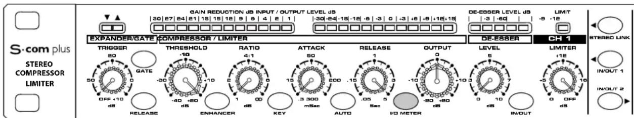
Controls and Functions
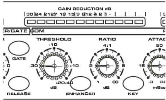
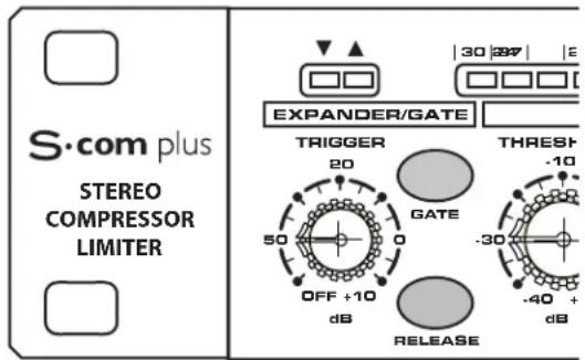
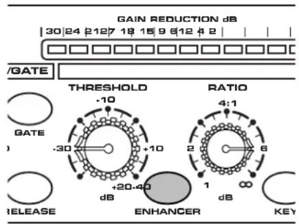
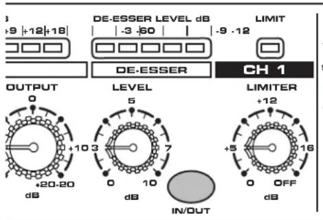
FRONT PANEL LAYOUT
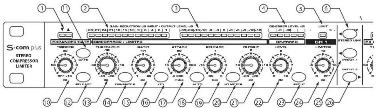
GATE OPEN & CLOSED LED -Indicates when the gate is open or closed.
2GAIN REDUCTION METER - Displays the amount of Gain Reduction when Compressor circuit is activated.
3INPUT/OUTPUT METER - Displays the Input or Output signal level based on the settings of the I/O meter switch.
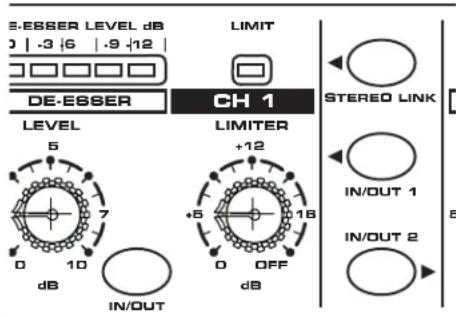
DE-ESSER METER - Displays the amount of De-Esser effect.
5LIMITER METER - Display light indicates when LIMITER circuit is engaged.
STEREO LINK SWITCH- When engaged Channel 2 functions are controlled by the settings on Channel 1.
CHANNEL 2 CONTROLS - The same knob and switch complement as Channel 1.
REAR PANEL LAYOUT
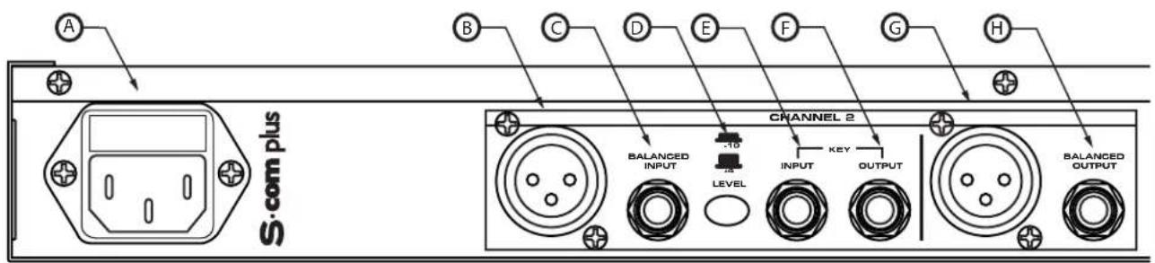
AC INLET-IEC standard AC Power cable Connector.
CHANNEL 2 XLR INPUT - XLR Balanced line input.
CHANNEL 21/4" TRS INPUT - 1/4" TRS Balanced line input.
OPERATING LEVEL SWITCH - Switches the operating level from -10dB to +4dB.
E CHANNEL 2 KEY INPUT - Input connection allowing external control of the S-com plus' Compressor detection circuit.
CHANNEL 1 KEY OUTPUT - S·com plus' detector circuit is sent here. Use the Key Output to process the compressor's detector through an external effect like an equalizer.
Controls and Functions
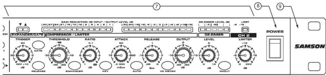
KEY SWITCH - Selects the key input so that an external signal may trigger the compressor.
17 ATTACK - Adjusts the amount of time the compressor takes to reach full gain reduction.
18 AUTO - Activates S · com plus' AEG (Auto Envelope Generator) which dynamically adjusts the attack and release time based on signal content.
19 RELEASE - Adjusts the length of time the compressor takes to return the signal to its original level.
20 INPUT/ OUTPUT METER SELECT SWITCH - Selects either Input or Output level to be displayed on the Input/Output Meter.
21 LEVEL - Controls the amount of Output level.
DE-ESSER LEVEL - Displays light indicating when Limiter circuit is engaged.
DE-ESSER IN/OUT Switch - Activates DE-ESSER circuit.
24 Limiter - Sets the level at which LIMITING begins.
CHANNEL 1 IN/OUT - Activates S-com plus Channel 1.
CHANNEL 2 IN/OUT - Activates S-com plus Channel 2.
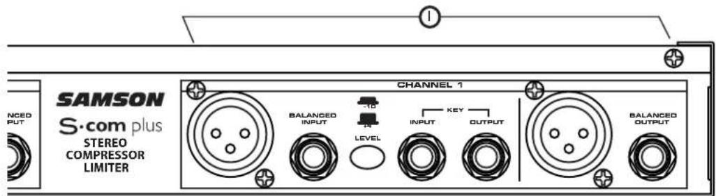
G CHANNEL 2 XLR OUTPUT - XLR Balanced line output.
CHANEL 2 1/4" TRS OUTPUT - 1/4" TRS Balanced line output.
① CHANNEL 1 - Same inputs and outputs as Channel 1.
Operating The S·com plus
Whether you are an experienced audio engineer, just starting out, or you just want to experiment, follow the steps below to get going. Further sections in this manual will cover basic dynamics and the associated parameters, system set-ups and applications for using dynamics processing in recording and live sound applications.
SETTING UP THE S·com plus
- Connect one or both sets of inputs and outputs to the designated connectors on the rear panel.
- Set the controls to the following positions:
EXPANDER/GATE TRIGGER-OFF
GATE SWITCH - OUT
FAST RELEASE - OUT
COMPRESSOR THRESHOLD - +20dBu (fully clockwise)
ENHANCER - OUT
RATIO-1:1
KEY SWITCH - OUT
ATTACK - 0.3 (fully counter-clockwise)
AUTO SWITCH-OUT
RELEASE - 5 (fully clockwise)
METER SWITCH - IN
OUTPUT LEVEL - O dBu
DE-ESSER - 0 (fully counter-clockwise)
DE-ESSER SWITCH - OUT
LIMITER-OFF (fully clockwise)
STEREO LINK SWITCH - OUT
CHANNEL 1 ENGAGE - OUT
In this configuration, the S-com plus is simply passing audio at unity gain with no dynamics processing. It is a good idea to check your gain structure at this point. Use the Input/Output meter to match the level.
- Send a signal to either or both of the S-com plus' inputs and outputs.
- Press the METER switch to see that the input and output levels are matched.
COMPRESSING A SIGNAL
S-com plus' Compressor section can be used for a variety of gain management tasks including printing signals to a multi-track recorder, as a mix-down effect, mastering, and for increasing the loudness of a live PA system. To begin compressing your signal, follow the steps below:
- Follow the section above, "SETTING UP THE S-com plus" for normalizing the controls.
- Press the CHANNEL IN switch (located in the middle of the unit) to the IN position.
Press in the AUTO switch (located in-between ATTACK and RELEASE).
Adjust the Ratio to 2:1.
Operating The S·com plus
- Now gradually turn down the THRESHOLD level and listen for the compression. For a visual representation, the amount of compression is indicated on the GAIN REDUCTION meter.
- Press out the AUTO button to experiment with manually controlled ATTACK and RELEASE times.
GATING A SIGNAL
Unwanted noises, buzzes and hisses can be easily removed by using S-com plus' GATE. The idea is to have the Gate open only when your desired signal is playing and to mute off (Gate closed) the unwanted noise, buzz and hiss. To Gate your signal, do the following:
- Follow the section above," SETTING UP THE S·com plus" for normalizing the controls.
- To engage the Gate, make sure that the EXPANDER/GATE switch is pressed in.
- Press the RELEASE switch to the IN position to select FAST release time.
- Now increase the THRESHOLD level and listen as the signal begins to gate. For a visual representation of the gate opening and closing, look at the GATE OPEN/CLOSED LED's located above the EXPANDER/GATE TRIGGER control.
You can set the S-com plus' Gate section to work as a DOWNWARD EXPANDER to lower the volume of a signal. Try the simple steps below:
- Follow the section above, "SETTING UP THE S-com plus" for normalizing the controls.
- To engage the EXPANDER, make sure that the EXPANDER/GATE button is switched to the OUT position.
- Press the RELEASE switch out to select a SLOW RELEASE.
- Now increase the TRIGGER level and listen as the signal begins to get softer.
Operating The S·com plus
USING THE ENHANCER
The S-com plus' ENHANCER switch can be engaged to activate the EFR (Enhanced Frequency Recovery) circuit. By engaging the ENHANCER, the S-com plus EFR restores the high frequency content that can be lost when high gain reduction is applied. The S-com plus EFR achieves this by adding back the high-end of the original signal in an amount that is equal to the amount of gain reduction.
- Follow the section above, "SETTING UP THE S·com plus" for normalizing the controls and run a signal such as a CD through the S·com plus.
- Press the CHANNEL IN switch (located in the middle of the unit) to the IN position.
- Press in the AUTO switch (located in-between ATTACK and RELEASE).
- Adjust the Ratio to 6 - 8:1.
- Switch on the ENHANCER and listen to how the high end is restored when the ENHANCER is on.
USING THE DE-ESSER
The S-com plus' De-Esser is a powerful tool for removing annoying problems like heavily sibilant vocal tracks or bright cymbals. To listen to the De-Esser try the following:
- Follow the section above, "SETTING UP THE S-com plus" for normalizing the controls.
To engage the De-ESSER, make sure that the DE-ESSER switch is pressed in. - Now increase the De-ESSER level and listen as the high frequency component of the signal begins get softer.
- You will see the amount of high frequency gain reduction displayed in the De-ESSER level meter.
Note: For Detailed De-Essing - Since the Compressor and DE-ESSER share the same ATTACK and RELEASE settings you may consider using one of the S-com plus' channels exclusively for DE-ESSING. Experiment with fast ATTACK and RELEASE times when using the channel for DE-ESSING only.
USING THE PEAK LIMITER
The Peak Limiter on S-com plus can be used in recording to insure that the output levels do not exceed a certain level and in PA applications, for speaker protection. To audition S-com plus' PEAK LIMITER try the following.
- Follow the section above, "SETTING UP THE S-com plus" for normalizing the controls.
- To engage the PEAK LIMITER, adjust the LIMITER threshold control knob to the maximum output level desired.
- The LIMIT LED above the LIMITER threshold control knob indicates when the limiter circuit is kicking in. If the LED does not light, you have not reached the maximum level.
Dynamics Processing 101
To begin to understand dynamics processing, we must first understand what dynamics are. Dynamics, or the dynamic range of a signal or audio device, is the amount of level between the softest and loudest possible output. Dynamics processing is applied to a signal to manage the changes in level. Various types of processing units are available to control dynamics including Noise Gates, Expanders, Compressors, Limiters and De-Essers. All of these processes have a unique effect on a signal, but one common element they share is that in one way or another they control gain. Some dynamics processors control gain in a subtle way by slightly reducing how soft and loud a signal is, while others make drastic changes in gain like reducing the signal until it's off. Applications for dynamics processing can be categorized by two distinct groups; first, to treat a signal that has an unpredictable dynamic range and make it predictable, and second, to create a "sound" by squeezing out the dynamic range. Whether used for a live sound application, recording, mixing or mastering, dynamic processors like the S-com plus are valuable tools for controlling gain. The following is a basic overview of dynamics processing and how it is used to improve the quality of recorded and live sound.
COMPRESSOR
A good compressor is one of the most useful tools in live sound and recording. Compressors are used to control the dynamic range of a signal, which offers a variety of benefits including leveling a signal that's being recorded, having an instrument sit in the mix, and increasing the loudness of a sound system to name a few. Drastic amounts of compression will also result in an effect that becomes more of a sound, than just controlling gain. To understand how a compressor works, it is necessary to become familiar with the basic parameters which include threshold, ratio, attack time, and release time.
Threshold
Threshold is the level that once the signal exceeds, gain reduction is applied. The normal range of adjustment for the threshold level is -40 to +20dB . If the threshold level is set above the highest level of the signal being sent to the compressors, the gain reduction is never triggered. Therefore, the compressor is virtually by-passed. If the threshold level is set very low so that any signal will trigger gain reduction, the compressor is working as an automatic leveler.
Ratio
The ratio control is used to set the proportion of gain reduction in relationship to the input signal. For example if the ratio is set to 2:1 and the signal crosses above the threshold level, an increase in level of 2 dB will produce a 1 dB increase in level at the output. A ratio setting of to 1 means that an infinite amount of input signal is needed to raise the output level by 1 dB. This means that the output level stays constant even when the input crosses over the threshold level.
Attack Time
Attack time is the amount of time that a compressor takes to effect the gain reduction after the signal rises above the threshold level. A well-designed compressor has adjustable attack times ranging from 100 s (microseconds) to 150 ms (milliseconds). A good compressor will sound smooth as it begins to control the gain regardless of the attack time.
Release Time
The release time is set to control how long the compressor takes to return the input signal back to its original level once the signal falls below the threshold level. The acceptable range for release time is from 50 s to 5 seconds. In normal use, faster release times are used for spoken word and longer release times are generally better for instrumental music.
Auto Attack and Release
Today, sophisticated compressors often incorporate a dynamic or Auto Attack and Release mode. The S-com plus' AEG (Auto Envelope Generator) is such a mode which when engaged, automatically adjusts the attack and release time based on the dynamically changing input signal.
Dynamics Processing 101 - Continued
Soft-Knee / Hard-Knee
In order to prevent harsh, unnatural envelopes on compressed signals sophisticated dynamics processors like the S-com plus feature an SKD (Smart Knee Detector) or automatic knee circuit. The Smart Knee Detector automatically switches from Soft-Knee when the signal is less than 10 dB over Threshold, to Hard-Knee when the signal is 10db above Threshold. In Soft-Knee mode, there is a gradual effect on gain change, which begins as the signal approaches the Threshold level. In Hard-Knee mode, gain reduction is linear based on the Threshold and Ratio controls. Any signal that falls below the Threshold level will be unprocessed.
Noise Gates
Noise gates are used to remove unwanted noise and/or bleed from recorded tracks in the studio or from open microphones in live sound systems. Noise gates can also be used as a sound effect, most commonly to chop the end of a reverb let's say on a snare drum so that the entire snare sound ends just before the beat. The basic principle of a noise gate is to work as an automatic mute switch. Mute off (Gate Open) when the desired signal is present and mute on (Gate Closed) when the desired signal is not present. In order to get the gate to work predictably, it is necessary to set a threshold, or trigger level that will determine when the gate will open. If the signal is below the trigger the gate will remain closed. When the signal is above the trigger, the gate will trigger open allowing the desired signal to pass and be heard. Noise gates often have other adjustable controls like attack, hold, range and release. Many noise gates like the S-com plus use sophisticated circuits to control some of these parameters automatically.
Downward Expander
The purpose of a well-designed Downward Expander is to increase the perceived dynamic range of a system. This is accomplished by decreasing the gain during the softer sections, thereby lowering the relative noise floor. When the signal level is below the desired trigger level, the expander lowers the overall gain by the selected amount.
Limiter
A Limiter is a specific form of a compressor configured to prevent peaks and for general overload protection. The S-com plus offers a Limiter section with independent controls designed to work in conjunction with the Compressor section. The operating range of the Limiter is from 0 to +20dB and when engaged, protects against signal peaks, overloads and excess modulation in broadcast situations.
Stereo Link Mode
The S-com plus can be configured from dual-mono operation to stereo by using the Stereo Link switch. In Stereo Link mode, Channel 2 functions are controlled by the settings of Channel 1 with the exception of IN/OUT, KEY and LIMITER.
Side Chain / External Key
The S-com plus features a side-chain or external Key function. The external Key function is used to externally process the compressor's detector circuit. There are many useful applications for processing the detector circuit including Equalizing for frequency dependent compression, De-Essing - the use of EQ to remove sibilance, and externally keying off a vocal track for Ducking effects to name a few. Selecting the Key function on S-com plus' front panel, interrupts the compressors detector path and routes it to the Key Output jack. The Key Input jack receives the externally processed signal, which will now control the compressor's detector.
Applications
Using the Expander/Gate to Remove Hiss and Noise
The S-com plus is an extremely useful tool in reducing the level of unwanted noises. By using the Expander/Gate you can effectively fade the noise into the noise floor or abruptly turn the unwanted signal completely off.
Let's say you want to reduce the bleed or cross talk that occurs when different instruments are recorded in close proximity to each other. You have recorded an acoustic guitar simultaneously in the same room as with some other acoustic instruments. The problem is that you hear a lot of the other instruments playing when the acoustic guitar is silent. This can cause phasing and comb filtering problems due to microphone placement, so having the bleeding signal drop into the noise floor is desirable. To do this, set the S-com plus to Expander mode with the Release switch to Slow and adjust the Threshold so that the acoustic guitar signal is well above the threshold level. When the signal from the acoustic guitar track falls below the threshold level, the signal subtly fades into the noise floor.
Now let's say you're attempting to remove the pick-up noise and hum from a guitar track that was recorded through a loud amplifier. The hum and noise is most noticeable in-between the rhythm of the performance, so you want to have the gate close during the silent parts and open during the musical passages. To do this, set the S-com plus to Gate mode and adjust the Trigger level so that the gate is open just during the musical guitar parts, and so that the gate is closed during the silent passages so that the hum and noise is muted.
Gating Drums
Using noise gates on drums is particularly useful in recording and in live sound. When a drum kit is set up with individual microphones on each drum in a live PA system, there's potential for great sound. However, there are several gain management problems that can occur. Several microphones like the ones on the tom-toms, will only be used occasionally and until the time that the tom-tom is actually played, its microphone is merely picking up unwanted sound from other instruments on stage. This adds a lot of unwanted mush in the mix and also adds to feedback problems. Use the S-com plus to gate the signal of the tom-tom by selecting Gate with the Expander/Gate switch. Now adjust the Trigger control so that the gate opens only when the tom-tom is played, and at the same time, so that the gate is closed even when the adjacent tom-tom is played. This same technique is useful on drums that have been recorded on individual tracks. By using the Gate to mute the bleed of the other drums, you can effectively reduce the comb filtering produced by phase cancellation due to microphone proximity.
Gating Longer Sounds
When using a noise-gate on sound with a longer decay like piano, it is usually necessary to use a longer release time. Run the piano signal through the S-com plus and set the Expander/Gate Release switch to Slow. Adjust the Trigger level on sustained passages to get the best results. Be sure to listen for the natural decay of the instrument and allow the gate to remain open until just after end of the decay.
Applications
Leveling a Vocal Track
When recording a vocal track, the vocalist may change the distance between them and the microphone, or they may naturally have a lot of dynamic range in their performance. In either case, the sound engineer must decide how much compression should be used to balance the natural performance and printing a good level to tape or disk. Set up the S-com plus with a medium attack and release time and a ratio of 4:1. You can also use the Auto button to engage the AEG (Auto Envelope Generator) for automatic attack and release. Now adjust the Threshold level so that the Gain Reduction meters show 6 to 10 dB of gain reduction. Adjust the Ratio control if necessary.
Leveling a Guitar or Bass
Guitar and especially bass guitar can have a lot of level change between strings and even frets on the fingerboard. Using compression when recording guitars and bass will even out these differences. Set up the compressor section of the S-com plus with a medium attack and release time and a ratio of 4:1. You can also use the Auto button to engage the AEG (Auto Envelope Generator) for automatic attack and release. Now adjust the Threshold level so that the Gain Reduction meters show 10 to 12 dB of gain reduction. You'll notice that the each note is at the same loudness and the overall sustain is increased.
Compressing Drums
Adding compression on drums can make a boomy kick drum tighten up, almost as if you were tightening the head of a drum. Set the S-com plus to a fairly quick attack time and use a ratio of 6:1. Set the Threshold so that the Gain Reduction meter reads 12 to 15 dB. Adjust the Ratio control if necessary. You can use the same basic setup on snare and toms as well.
Getting a Track to Sit in the Mix
By using a heavy amount of compression you can get the effect of the vocal suspending in the mix. While this may be a bit radical for some, the effect can be dramatic especially if the vocal is mixed without any reverb or delay. Set up the compressor section of the S-com plus with a medium attack and release time and a ratio of 6:1. You can also use the Auto button to engage the AEG (Auto Envelope Generator) for automatic attack and release. Now adjust the Threshold level to so that the Gain Reduction meters show 21 to 24 dB of gain reduction.
Speaker Protection
There are several ways to use a compressor to protect a speaker system and many considerations can be made including whether the speaker system is crossed over actively or passively.
If the speaker system is stereo using a passive crossover, then the line output of the mixer or equalizer is run directly into the S·com plus inputs. The S·com plus should be last in the chain before the power amps with its outputs feeding the inputs of the amp. Now set the S·com plus to Stereo Link mode and use the Auto button to engage the AEG (Auto Envelope Generator) for automatic attack and release. Adjust the Threshold and Ratio so that the system's entire dynamic range is under control. Set the Limiter control to +12 and gradually adjust it until it is 1 to 2dB below the clip level of your power amps.
When using an active crossover, multiple compressors can be used to compress each section of the PA. For example, if the PA is using an active crossover to run a four-way mono system, two S-com plus' can be used for four band compression. By compressing each output of the crossover, you can maximize the output level while minimizing the gain to sensitive speakers like the mid-range. Run the low and low-mid frequencies into two channels of the first S-com plus and the high-mid and high frequencies into channel one and two of the second S-com plus.
S·com plus System Set-Ups
In this example, the S-com plus is inserted after the mixer and before the graphic equalizer, thereby compressing the full range signal from the mixer.
S·com plus System Set-Ups
LIVE SOUND SYSTEM WITH MULTIBAND COMPRESSION
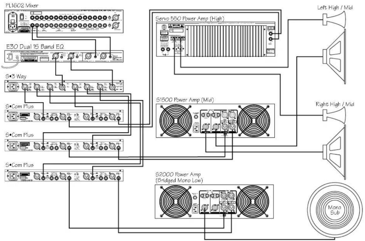
In this example, three S-com plus' are inserted after the mixer, equalizer and crossover, thereby providing individual compression on the low, mid and high frequencies.
S·com plus Connections
CONNECTING THE S·com plus
The are several ways to interface the S-com plus to support a variety of applications. The S-com plus features servo-balanced inputs and outputs, so connecting balanced and unbalanced signals is possible without any signal loss. The S-com plus can be used on a single instrument by connecting to a channel's insert points, or on an entire mix "in-line" between a mixer's outputs and a power amp or equalizer.
INSERT POINTS
Many mixers today provide channel and bus or group inserts. Insert points are input and output patch points that interrupt the channel or bus signal so that external processors can be connected. Channel insert points are ideal for connecting to when using the S-com plus to process a single channel like a vocal, bass or guitar. Bus insert points are ideal for compressing groups of instruments like vocals, strings or drums. If you are connecting to a channel's insert points, you may have a single TRS jack for Send & Return. In this case, use an Insert "Y" Cable that configured like the one in the wiring diagram below.
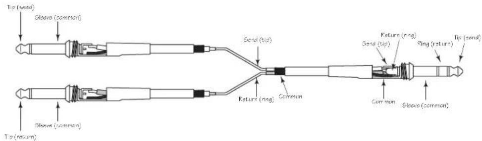
Insert Cable 1 / 4'' male TRS connector to two male 1 / 4'' in send and return configuration.
IN-LINE
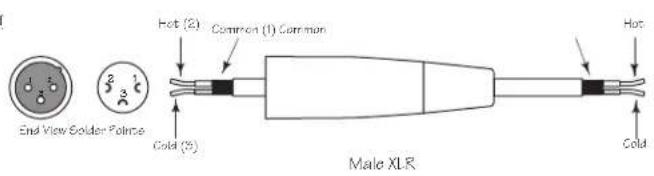
In live sound operation the S-com plus can be installed in-line between a mixer and equalizer or power amplifier. For these applications the S-com plus provides both 1/4'' TRS connectors and XLR connectors to easily interface with most any professional audio device. Follow the wiring examples below for your particular installation.
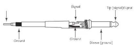
Unbalanced 1/4'' Connector
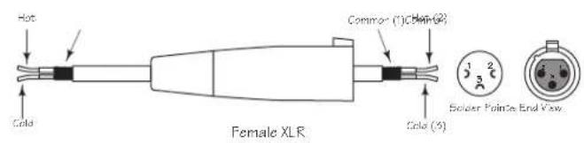
XLR Balanced Wiring Guide
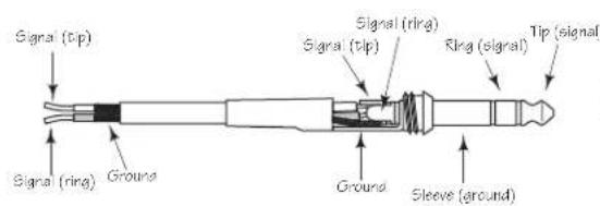
Balanced TRS 1/4" Connector
Note de Ray Kennedy
S·com plus Anschlüsse
S·com plus ANSCHLIESSEN
System Specifications
Frequency Response < 10Hz to 20kHz + 0 / - 0.1 dB effect out, -0.4@100kHz
<10Hz to 20kHz +0 / -0.1 dB effect in, -3dB @ >100kHz
Dynamic range 116 dB, un-weighted, 22Hz to 22kHz
THD 0.008 % typ. @ +4 dBu, 1 kHz Effect out, 0.016% effect in
Crosstalk >100dB 22Hz to 22kHz
Operating Level Selectable +4dBu / -10 dBV
Max. Input Level +21dBu, balanced
CMRR Min. 40dB, >50dB @ 1kHz
Max. Output Level +21dBu, balanced
Balanced Input
Connectors XLR and 1 / 4^ TRS jack
Impedance >20K Ohms balanced or unbalanced
Balanced Output
Connectors XLR and 1 / 4^ TRS jack
Impedance 60 Ohms balanced or unbalanced
Key Input
Connector 1/4" jack
Impedance 10 k Ohm
Max. Input Level +21 dBu
Key Output
Connector 1/4" jack
Impedance 47 Ohms
Max. Output Level +21 dBu
Expander/Gate
Trigger range
Attack
Release
Ratio
Variable (Off to +10 dB)
<1 ms per 50 dB
Variable (Slow:100 ms / 1dB, Fast:100 ms / 100 dB)
Expander 1:2, Gate 1:16
Compressor Section
Detector
Threshold
Ratio
RMS
-40 dB to +20 dB
Variable (1:1 to infinity : 1)
Manual Attack Time Variable (0.3 ms / 20 dB to 300 ms / 20dB)
Manual Release Time
Output gain
Variable (0.05 to 5 Sec)
Variable (-20 to +20 dB)
Peak Limiter Section
Threshold
Ratio
Limiter
Attack
Variable 0 to Off
Preset
Ceiling type
<5 ms
Release Typ. 20dB/s
De-Esser
Trigger range
Maximum
variable (off to 12dB)
12dB Gain Reduction mid / high band
Specifications
Function Switches
Gate Gate or Expander
Release Fast/slow
Enhancer In/Out
In/Out Bypass
Key Switches the detector section to external key input
Auto Sets automatic attack and release times and automated timing - program dependent
I/O Meter Switches the Input/Output meter to read input or output level
De-Esser In/Out
Stereo Link Links both channels for stereo operation. Channel 1 becomes master.
Operating Level (Rear Panel) Changes the internal reference level from +4dBu to -10dBV
Meters & LED's
Gain Reduction 12 segment LED display
30/27/24/21/18/15/12/9/6/4/2/1dB
Input/Output level 12 segment LED display:
-30/-24/-18/-12/-6/-3/0/+3/+6/+9/+12/+18dB
Expander/Gate Threshold 2 LED's Gate open, Gate closed
Peak Limiter Threshold 1 LED for Indication of Limiter function
Function switch LED indicator in each (except Operating Level Switch)
Power Supply
Mains Voltages USA/Canada 105 - 125 VAC ~, 60 Hz
Mains Voltages Europe
Power Consumption
Power inlet
215-254VAC\~,50/60Hz
10 Watts
Standard IEC receptacle/with fuse
Physical
Dimensions
Net Weight
Shipping Weight
1 3/4 (44.5 mm) x 19 (482.6 mm) x 7 3/4 (197 mm)
5lbs., (2.3 kg)
7.5lbs., (3.4 kg)
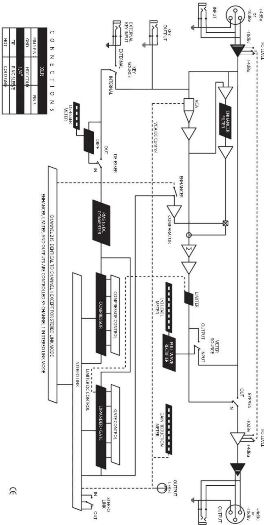
Block Diagram
Notes
Notes
Samson Technologies Corp.
575 Underhill Blvd.
P.O.Box 9031
Syosset, NY 11791-9031
- CAUTION
- ATTENTION
- WARNING
- AVIS
- Forward By Ray Kennedy
- Introduction
- S·com plus Features
- Controls and Functions
- FRONT PANEL LAYOUT
- REAR PANEL LAYOUT
- Operating The S·com plus
- SETTING UP THE S·com plus
- COMPRESSING A SIGNAL
- GATING A SIGNAL
- USING THE ENHANCER
- USING THE DE-ESSER
- USING THE PEAK LIMITER
- Dynamics Processing 101
- COMPRESSOR
- Threshold
- Ratio
- Attack Time
- Release Time
- Auto Attack and Release
- Dynamics Processing 101 - Continued
- Soft-Knee / Hard-Knee
- Noise Gates
- Downward Expander
- Limiter
- Stereo Link Mode
- Side Chain / External Key
- Applications
- Using the Expander/Gate to Remove Hiss and Noise
- Gating Drums
- Gating Longer Sounds
- Leveling a Vocal Track
- Leveling a Guitar or Bass
- Compressing Drums
- Getting a Track to Sit in the Mix
- Speaker Protection
- S·com plus System Set-Ups
- LIVE SOUND SYSTEM WITH MULTIBAND COMPRESSION
- S·com plus Connections
- CONNECTING THE S·com plus
- INSERT POINTS
- IN-LINE
- Note de Ray Kennedy
- S·com plus Anschlüsse
- S·com plus ANSCHLIESSEN
- Specifications
- Block Diagram
- Notes
Brand : SAMSON
Model : Scom plus
Category : Processor