
Go Mic Mobile HXD2 - Microphone SAMSON - Free user manual and instructions
Find the device manual for free Go Mic Mobile HXD2 SAMSON in PDF.
| Brand | Samson |
| Model | Go Mic Mobile HXD2 |
| Category | Dual wireless microphone system |
| Transmitter type | HXD2 (pocket) and PXD2 (beltpack) |
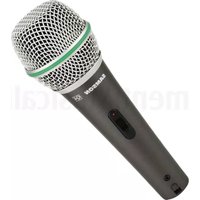
| HXD2 microphone type | Unidirectional |
| GMM receiver power supply | Internal rechargeable lithium-ion battery |
| GMM receiver battery life | 7 to 13 hours |
| Receiver charging time (fast charge) | 3 hours |
| Receiver charging time (standard USB port) | 10 hours |
| Transmitter power supply | 2 AA (LR6) batteries each |
| Transmitter battery life | 20 hours |
| Range | 30 m (100 ft) line of sight |
| Operating frequency | 2.406 – 2.478 GHz |
| Frequency response | 10 Hz – 22 kHz |
| Audio outputs | Analog 3.5 mm, digital USB (Micro USB) |
| USB audio sample rate | 48 kHz |
| Compatibility | iOS, Android (5.0+), Mac OS, Windows, Linux |
| Included accessories | Cables (Micro USB-Lightning, Micro USB-Micro USB, Micro USB-USB-C, Mini B-USB A, audio 3.5 mm), shoe mount adapter, Velcro straps |
| Maintenance | Clean with a dry cloth |
| Safety | Do not expose to rain or moisture, do not open the housing |
Frequently Asked Questions - Go Mic Mobile HXD2 SAMSON
User questions about Go Mic Mobile HXD2 SAMSON
0 question about this device. Answer the ones you know or ask your own.
Ask a new question about this device
Download the instructions for your Microphone in PDF format for free! Find your manual Go Mic Mobile HXD2 - SAMSON and take your electronic device back in hand. On this page are published all the documents necessary for the use of your device. Go Mic Mobile HXD2 by SAMSON.
USER MANUAL Go Mic Mobile HXD2 SAMSON
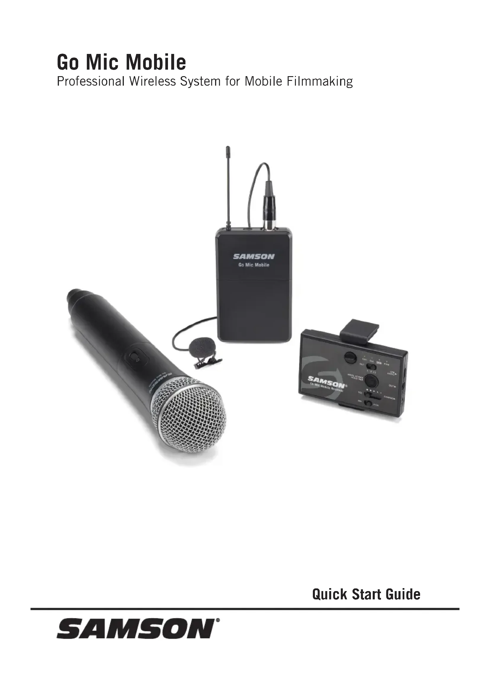
Professional Wireless System for Mobile Filmmaking
natural_image
Exterior view of three wireless audio devices: a microphone, a Go Mic Mobile device, and a smartphone (no visible text or symbols on main objects)Quick Start Guide
Important Safety Information

ATTENTION RISQUE D'ÉLECTROCUTION ! NE PAS OUVRIR !
CAUTION: TO REDUCE THE RISK OF ELECTRIC SHOCK, DO NOT REMOVE COVER (OR BACK). NO USER-SERVICEABLE PARTS INSIDE. REFER SERVICING TO QUALIFIED SERVICE PERSONNEL.
This lightning flash with arrowhead symbol within an equilateral triangle is intended to alert the user to the presence of non-insulated
"dangerous voltage" within the product's enclosure that may be of sufficient magnitude to constitute a risk of electric shock.

The exclamation point within an equilateral triangle is intended to alert the user to the presence of important operating and
maintenance instructions in the literature accompanying the appliance.
WARNING
TO PREVENT FIRE OR SHOCK HAZARD. DO NOT USE THIS PLUG WITH AN EXTENSION CORD, RECEPTACLE OR OTHER OUTLET UNLESS THE BLADES CAN BE FULLY INSERTED TO PREVENT BLADE EXPOSURE. TO PREVENT FIRE OR SHOCK HAZARD. DO NOT EXPOSE THIS APPLIANCE TO RAIN OR MOISTURE. TO PREVENT ELECTRICAL SHOCK, MATCH WIDE BLADE PLUG TO WIDE SLOT AND FULLY INSERT.

If you want to dispose this product, do not mix it with general household waste. There is a separate collection system for used electronic products in accordance with legislation that requires proper treatment, recovery and recycling.
Private households in the 28 member states of the EU, in Switzerland and Norway may
return their used electronic products free of charge to designated collection facilities or to a retailer (if you purchase a similar new one).
For Countries not mentioned above, please contact your local authorities for a correct method of disposal.
By doing so you will ensure that your disposed product undergoes the necessary treatment, recovery and recycling and thus prevent potential negative effects on the environment and human health.
Copyright 2020, Samson Technologies Corp. v6
Samson Technologies Corp.
278-B Duffy Ave
Hicksville, NY 11801
www.samsontech.com
Important Safety Information
- Read these instructions.
- Keep these instructions.
- Heed all warnings.
- Follow all instructions.
- Do not use this apparatus near water.
- Clean only with dry cloth.
- Do not block any ventilation openings. Install in accordance with the manufacturer's instructions.
- Do not install near any heat sources such as radiators, heat registers, stoves, or other apparatus (including amplifiers) that produce heat.
- Do not defeat the safety purpose of the polarized or grounding type plug. A polarized plug has two blades with one wider than the other. A grounding type plug has two blades and a third grounding prong. The wide blade or the third prong are provided for your safety. If the provided plug does not fit into your outlet, consult an electrician for replacement of the obsolete outlet.
-
Protect the power cord from being walked on or pinched particularly at the plugs, convenience receptacles, and at the point where they exit from the apparatus.
-
Only use attachments/accessories specified by the manufacturer.
-
Use only with the cart, stand, tripod, bracket, or table specified by the manufacturer, or sold with the apparatus. When a cart is used, use caution when moving the cart/apparatus combination to avoid injury from tip-over.
-
Unplug the apparatus during lightning storms, or when unused for long periods of time.
- Refer all servicing to qualified personnel. Service is required when the apparatus has been damaged in any way, such as power supply cord or plug is damaged, liquid has been spilled or objects have fallen into the apparatus, has been exposed to rain or moisture, does not operate normally, or has been dropped.
- This appliance shall not be exposed to dripping or splashing water and no object filled with liquid such as vases shall be placed on the apparatus.
- Caution-to prevent electrical shock, match wide blade plug wide slot fully insert.
- Please keep a good ventilation environment around the entire unit.
- The direct plug-in adapter is used as disconnect device, the disconnect device shall remain readily operable.
- Batteries (battery pack or batteries installed) shall not be exposed to excessive heat such as sunshine, fire or the like.

natural_image
Silhouette of a person climbing a ladder inside a circular frame (no text or symbols)Important Safety Information
FCC Notice
- This device complies with Part 15 of the FCC Rules. Operation is subject to the following two conditions:
(1) This device may not cause harmful interference.
(2) This device must accept any interference received, including interference that may cause undesired operation.
- Changes or modifications not expressly approved by the party responsible for compliance could void the user's authority to operate the equipment.
FCC Statement
This equipment has been tested and found to comply with the limits for a Class B digital device, pursuant to Part 15 of the FCC Rules. These limits are designed to provide reasonable protection against harmful interference in a residential installation.
This equipment generates, uses, and can radiate radio frequency energy and, if not installed and used in accordance with the instructions, may cause harmful interference to radio communications. However, there is no guarantee that interference will not occur in a particular installation. If this equipment does cause harmful interference to radio or television reception, which can be determined by turning the equipment off and on, the user is encouraged to try to correct the interference by one or more of the following measures:
- Reorient or relocate the receiving antenna.
- Increase the separation between the equipment and receiver.
- Connect the equipment into an outlet on a circuit different from that to which the receiver is connected.
- Consult the dealer or an experienced radio/TV technician for help.
RF Exposure Statement (SAR)
This device is designed and manufactured not to exceed the emission limits for exposure to radio frequency (RF) energy set by the Federal Communications Commission of the U.S. Government.
The exposure standard for wireless device employs a unit of measurement known as the Specific Absorption Rate, or SAR. The SAR limit set by the FCC is 1.6W/kg. Tests for SAR are conducted using standard operating positions accepted by the FCC with the device transmitting at its highest certificated power level in an tested frequency bands.
To maintain compliance with the FCC RF exposure requirements.
The maximum summation of SAR was: 0.90W/Kg 1g Body SAR for GMM, 0.61W/Kg 1g Body SAR for HXD2, 0.48W/Kg 1g Body SAR for PXD2.
WARNING: The battery (battery or batteries or battery pack) shall not be exposed to excessive heat such as sunshine, fire or the like.
Hereby, Samson Technologies Corp., declares that this Go Mic Mobile Wireless System is in compliance with the essential requirements and other relevant provisions of Directive 2014/53/EU. The declaration of conformity may be consulted at:
http://www.samsontech.com/site_media/support/manuals/GMM_DOC.pdf
Introduction
Congratulations on purchasing the Samson Go Mic Mobile Wireless System. The Go Mic Mobile is a dual wireless system designed to deliver professional quality audio for mobile video. Pair and mix two transmitters to the GMM and turn your mobile device into a complete video production studio. It is the ideal solution for mobile journalists, filmmakers, videographers or anyone looking to add wireless audio to their video projects.
The Go Mic Mobile includes all the cables needed to connect the Go Mic Mobile Receiver (GMM) to a smartphone or digital camera (with an audio input). The Go Mic Mobile will work with iOS, Android, Mac OS and Windows devices. The locking mount arms enable the Go Mic Mobile receiver to mount directly onto the rear of a smartphone out of the way of the phone's lens. The arms can be removed to attach the receiver to a tablet (using the included hook-and-loop strips) or affix to a camera using the included shoe mount adapter.
In these pages, you'll find a detailed description of the features of the Go Mic Mobile wireless system, instructions for its setup and use, and specifications. If your wireless system was purchased in the United States, you'll also find a registration card enclosed—don't forget to follow the instructions so that you can receive technical support and so that we can send you updated information about this and other Samson products in the future. Also, be sure to check out our website (www.samsontech.com) for complete information about our full product line.
We recommend you keep the following records for reference, as well as a copy of your sales receipt.
Transmitter & Receiver Serial number: ____
Date of purchase: ____
If you have any questions or comments regarding the Go Mic Mobile Wireless Microphone System or any other products from Samson, do not hesitate to contact us at support@samsontech.com.
With proper care and maintenance, your Go Mic Mobile Wireless System will operate trouble-free for many years. Should your Go Mic Mobile Wireless System ever require servicing, a Return Authorization (RA) number must be obtained before shipping your unit to Samson. Without this number, the unit will not be accepted. Please visit www.samsontech.com/ra for an RA number prior to shipping your unit. Please retain the original packing materials and, if possible, return the unit in its original carton. If your Go Mic Mobile Wireless System was purchased outside of the United States, contact your local distributor for warranty details and service information.
Charging the Go Mic Mobile Receiver Battery
The Go Mic Mobile Receiver has an internal lithium-ion rechargeable battery. The receiver is charged via the Mini USB jack located on the side of the receiver.
To charge the receiver, use the included USB charging cable and AC adapter. Charging may also be done with 3rd party AC 5V adapters, or by connecting the units to a standard computer USB port.
The total full charge time is 3 hours if you use a fast charger or a fast-charging USB port (with a lightning symbol next to it), but if connected to a “standard computer USB port” it will take 10 hours. The max run time from a full battery is approximately 7–13 hours.
Note: The Go Mic Mobile receiver does not recharge from the Micro USB port, so the battery level will decrease if plugged into a computer. If you want to power the receiver while it is connected to a device, you will also need to connect the Mini USB port to the computer or AC adapter.
Getting the most out of the rechargeable battery:
- Completely charge the batteries before first use
- Fully charge the battery before it will be used.
- After the battery is charged, unplug the adapter from the outlet.
- The optimal temperature range for using and storing the battery is 50^ F - 86^ F ( 10^ C - 30^ C). The battery performance and operation may decrease in temperatures below 50^ F ( 10^ C).
- To extend the battery life, power off the Go Mic Mobile receiver when not in use.
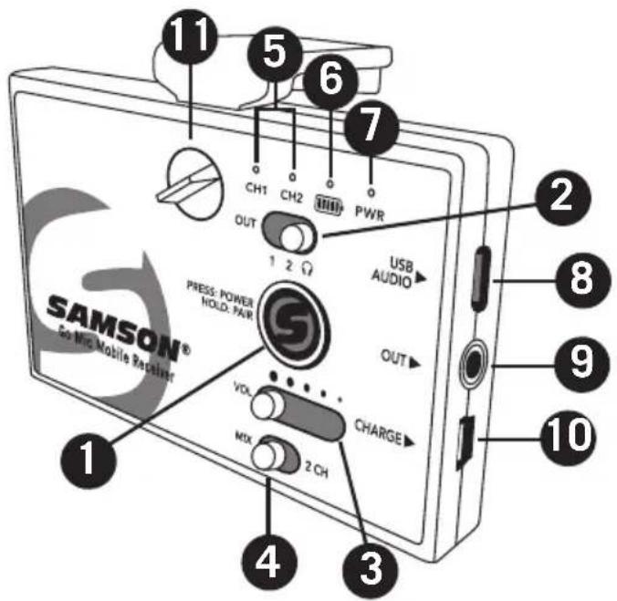
Go Mic Mobile Receiver (GMM) Callouts
-
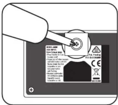
Power/Pair Switch - Press less than 5 seconds to turn the unit on or off. Press and hold for more than 5 seconds to enter pairing mode. Note: The Go Mic Mobile receiver and transmitter are pre-paired from the factory.
-
Analog Output Select Switch - Sets the wiring of the analog output. The OUT 1 & 2 positions are for connecting to a smartphone's TRRS headset input. The Headphone/Line output is for connecting the receiver to a camera, mixer or headphones.
-
VOL Control - This slider sets the level of the audio signal sent to the receiver's digital and analog outputs.
-
MIX / 2 CH Switch - Sets the receiver audio output to either mixed mono or split left and right.
-
CH 1 & CH 2 Indicators - When lit white, the LEDs indicate the receiver is paired with a transmitter. When the transmitter input or the receiver output is clipped, the LEDs flash red.
-
Battery Level Indicator - This indicator lights green when the battery is charged, lights red when the battery is low, and orange when the battery is charging.
-
Power Indicator - This indicator lights green when the Go Mic Mobile Receiver is powered on.
-
USB AUDIO Output - Use this output when connecting to a digital audio input.
-
OUT Jack - Use this 3.5mm jack when connecting to an analog input or headphones.
-
USB CHARGE Port - Use this Mini USB jack to connect the Go Mic Mobile Receiver to the included AC adapter to charge the receiver's internal battery.
-
Lock Screw - Turn left to loosen the screw and adjust the mounting arm. Turn right to lock the mounting arm in place.
Go Mic Mobile Receiver (GMM) Callouts
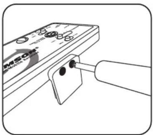
12. Adjustable Mounting
Arm - This mounting arm is adjustable to affix the GMM Receiver to a smartphone. To adjust, loosen the Lock Screw on the top of the GMM Receiver. To fix the arm in place, tighten the Lock Screw.
Note: The Adjustable Mounting Arm can be removed by loosening the Lock Screw, sliding the arm to the closed position, then unscrew the Lock Screw completely and remove. Now slide the Mounting Arm out of the GMM Receiver and replace the Lock Screw.
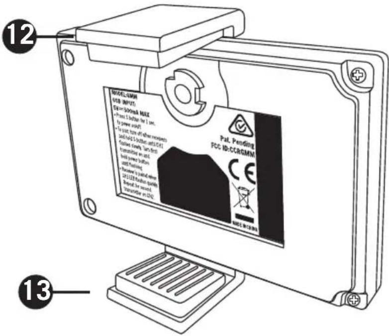
-
Fixed Mounting Arm - This fixed mounting arm is used to mount the GMM Receiver to a smartphone. A 1/4"-20 adapter is included to mount the GMM to a standard camera tripod. To remove the fixed mounting arm, unscrew the two Phillips screws.
-
Cold Shoe Adapter - This removable shoe mount adapter is used to affix the GMM Receiver to a camera or mobile filming case.
-
Hook and Loop Area - Use the included self adhesive hook and loop pieces to affix the GMM to a tablet. Before attaching the GMM to a tablet, remove the standard mounting arms and/or cold shoe adapter.

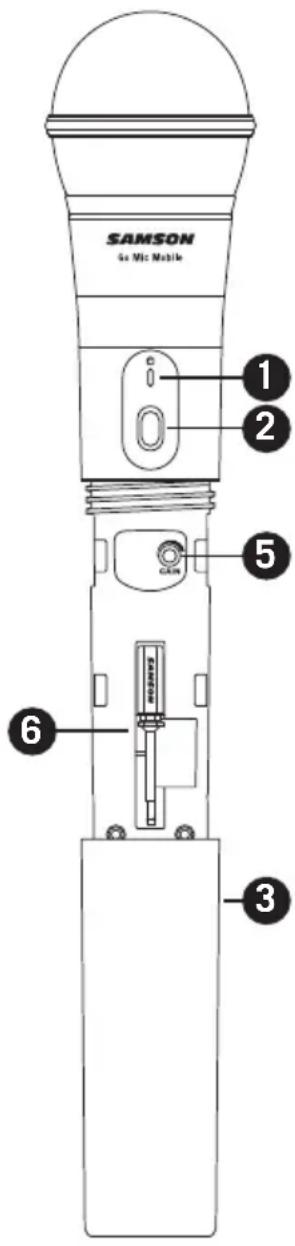
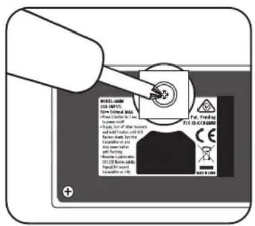
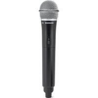
HXD2 Handheld Transmitter Callouts
- Status Indicator - This LED displays the operation mode.
- Power/Pair Switch - Press <5 seconds to turn the unit on or off. Press >5 seconds to enter pairing mode.
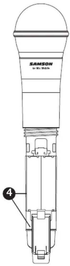
- Battery Cover - Unscrew the battery cover and slide down to open the Go Mic Mobile Handheld battery compartment.
- Battery Holder - Open the battery holder by pressing the tab and lifting the cover. Insert two standard AA (LR6) batteries here, being sure to observe the plus and minus polarity markings shown.
WARNING: Do not insert the batteries backwards; doing so can cause severe damage to the transmitter and will void your warranty.
- Input GAIN Control - This control adjusts the transmitter input sensitivity. This input sensitivity control has been factory preset to provide optimum level for the particular microphone capsule provided with the Go Mic Mobile system and so we recommend that this not be adjusted manually. If necessary, however, you can use the supplied plastic screwdriver to raise or lower the input level.
- Plastic Screwdriver - Used to adjust the input GAIN control.
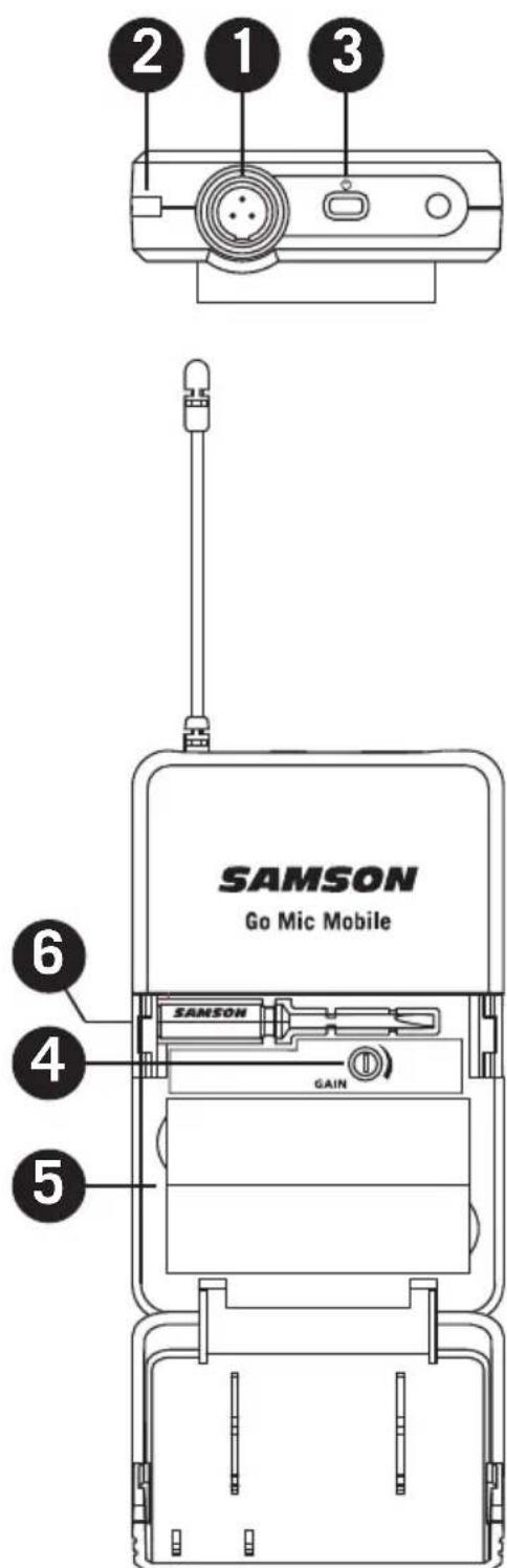
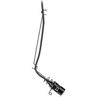
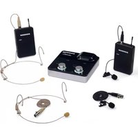
PXD2 Belt Pack Transmitter Callouts
- Input Connector - Connect the input device via the mini-XLR connector. The PXD2 is supplied with a lavalier microphone.
- Status Indicator - This LED displays the operation mode
- Power/Pair Switch - Press <5 seconds to turn the unit on or off. Press >5 seconds to enter pairing mode.
- Input GAIN Control - This control adjusts the transmitter input sensitivity.
- Battery Holder - Insert two standard AA (LR6) batteries here, being sure to observe the plus and minus polarity markings shown.
WARNING: Do not insert the batteries backwards; doing so can cause severe damage to the PXD2 and will void your warranty.
- Plastic Screwdriver - Used to adjust the input GAIN control.
Getting Started - Pairing
The Go Mic Mobile system will come paired from the factory. If you need to re-pair the system for any reason follow these steps:
- Turn on the Go Mic Mobile Receiver (GMM) and Go Mic Mobile transmitter by pressing their Power/Pair buttons for less than 5 seconds.
- On the GMM, press and hold the Power/Pair button for more than 5 seconds. The CH1 LED will start flashing slowly.
- On the Go Mic Mobile transmitter, press and hold the Power/Pair for more than 5 seconds. The transmitter LED will start flashing slowly.
- When the receiver and transmitter are paired the LEDs will quickly flash and the transmitter will light solid Green and the GMM CH 1 LED will light solid white. The Go Mic Mobile Receiver CH2 LED will now start flashing slowly.
- To pair a second transmitter, press and hold the Power/Pair button on the second transmitter for more than 5 seconds. The transmitter LED will start flashing slowly. When the receiver and transmitter are paired the LEDs will quickly flash and the indicator on the second transmitter will light solid green and the GMM CH 2 LED will light solid white.
Note: If you do not wish to pair a second transmitter, the receiver will time out of pairing mode after 20 seconds. - To re-pair the paired transmitters with the Go Mic Mobile receiver, press and hold the Power/Pair button on the receiver for more than 5 seconds. The receiver will erase the current paired transmitters and enter pairing mode. If no transmitters are paired with the receiver, the GMM will time out and return to the previously paired state.
Note: When pairing your Go Mic Mobile system, make sure only one GMM receiver is turned on and only one microphone is in pairing mode at a time.
Getting Started - Audio Connections
The Go Mic Mobile can be connected to a smartphone using the Micro USB digital output or 3.5mm analog output.
Connecting to an iOS device (iPhone, iPad or iPod Touch)
Using the included Micro USB to Lightning cable, connect the cable to the USB Audio Output jack on the GMM to the Lightning connector on the iOS device. Once connected, the iOS device will recognize the Go Mic Mobile as the audio input device.
Open a recording or video application and start recording.
Note: It is recommended to put your iOS device in Do Not Disturb mode or Airplane mode to eliminate the video or audio recording from being interrupted by a phone call. Leave Airplane Mode off to keep geolocation information tagged to your video files.
Connecting to an Android device with the digital audio output
Go Mic Mobile offers digital audio compatibility with Android devices running Android 5.0 (Lollipop) or later that allow USB digital audio connectivity. Not all Android applications support USB audio, and you may need to download a third party app to use this feature. To connect using the USB Audio Output jack, make sure your Android device can accept a digital audio input. Using the Micro USB to USB type-C or Micro USB to Micro USB cable, connect the cable to the Micro USB audio output on the GMM and the USB input of the Android mobile device.
Connecting to a mobile device with the analog audio output
If your mobile device does not accept digital audio input, the GMM can be connected using the 3.5mm analog output. When connecting to a smartphone, you will need to set the Analog Output Select Switch switch to either the Out 1 or Out 2 position. For most smartphones the Out 1 (CTIA / AHJ) position is the appropriate setting. If your mobile device uses OMTP wiring for the input, use the Out 2 position. For more information on smartphone wiring visit www.samsontech.com/support/go-mic-mobile
Connecting to a DSLR, cinema camera, or mixer
When connecting the GMM to a DSLR camera, cinema camera or mixer, use the included 3.5mm analog audio output. Set the Output Selector switch to the Line/Headphone setting.
Monitoring with the Go Mic Mobile
The GMM 3.5mm output can be used to monitor the audio transmitted to the receiver. The headphone output follows the MIX / 2 CH Switch. The level of the headphones is controlled by the VOL output slider and follows the output level of the USB Audio Output.
Getting Started - Setting the system volume
Good audio can vastly improve a poorly shot video, but bad audio can hurt any video. In order to achieve the best results when adding audio to video with the Go Mic Mobile, it is important to pay attention to the gain staging of the transmitters and receiver. If the signal is too high, it can overload or distort. Conversely if the signal is too low, you will need to raise it up in post-production which can add background noise.
The GMM Receiver CH 1 and CH 2 LEDs include peak or overload indication when the input to the receiver (signal sent from the transmitter) is overloaded. To set the level of the transmitters, while talking into the Go Mic Mobile Transmitter, turn the Gain control (inside the battery compartment) up until you reach a good recording level. If the corresponding CH indicator flashes red, turn the Gain control down until you no longer see the indicator flash red or it lights occasionally during very loud signals.
When the transmitter level is set, perform a test recording to set the level of the GMM Receiver. If the recording app has an input meter, adjust the GMM Receiver VOL control until the meter is as close to 0 dB (or clip) as possible without going over.
Note: The receiver VOL control does not affect the transmitter gain setting. For example, if the transmitters are sending a distorted signal, lowering the receiver volume will not fix the audio, it will only lower the overall level of the distorted signal.
MIX / 2 CH Switch
The GMM Receiver can be paired with two transmitters for audio from two independent sound sources. The MIX / 2 CH switch selects how the audio will be sent to the audio outputs of the receiver.
In the MIX position the two channels are mixed in mono on both the left and right audio tracks.
In the 2 CH switch position, the CH 1 transmitter is on the left audio channel and CH 2 transmitter is on the right audio channel. In 2 CH mode, each input can be routed to a separate track in your computer recording software. To do this create two mono tracks, and set the inputs to Samson Go Mic Mobile Left (Input 1) and Samson Go Mic Mobile Right (Input 2) respectively.
The MIX / 2 CH Switch mixes the audio prior to the audio outputs of the GMM Receiver. The audio from both transmitters will be present on the left and right audio tracks of your video or recording software.
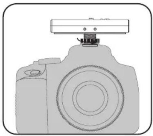
Go Mic Mobile Mounting Instructions
Mounting Accessories
natural_image
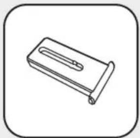
Simple line drawing of a mechanical bracket or bracket (no text or symbols)Adjustable Mounting Arm
natural_image
Simple line drawing of a rectangular object with a handle and rounded base, enclosed in a rounded square frame (no text or symbols)Insert Cover

natural_image
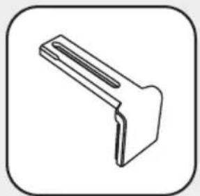
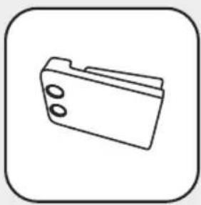
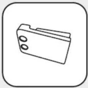
Simple line drawing of a folder icon (no text or symbols)Mounting Arm

natural_image
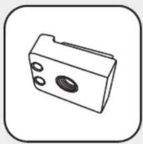
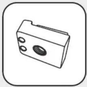
Simple line drawing of a rectangular mechanical component with circular holes and a central oval (no text or symbols)1/4"-20 Mounting Arm
natural_image
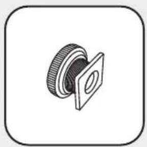
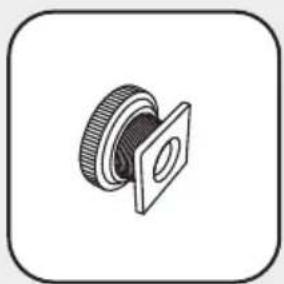
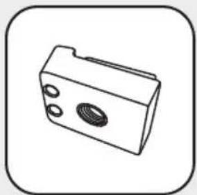
Technical illustration of a mechanical component with a flanged housing and threaded shaft (no text or symbols)Cold Shoe Adapter

natural_image
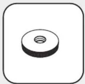
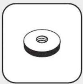
Simple 3D illustration of a circular wash or nut with a central hole, enclosed in a rounded square border (no text or symbols)Thumb Screw
natural_image
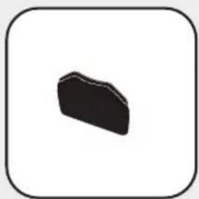
Simple black irregular shape inside a rounded square frame (no text or symbols)Large Hook-and-loop

natural_image
Simple black oval shape centered inside a rounded square frame (no text or symbols)Small Hook-and-loop
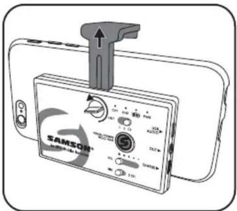
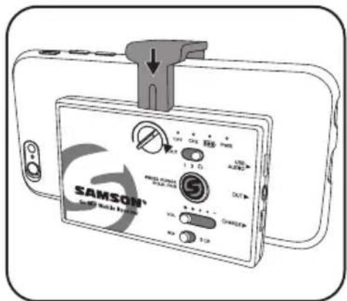
Mounting to a smartphone
- Loosen the Lock Screw until the Adjustable Mounting Arm can be moved.
- Position the receiver on the rear side of the smartphone.
- Slide the Adjustable Mounting Arm so that it is tight with the edge of the smartphone.
- Apply pressure to the Adjustable Mounting Arm and tighten the Lock Screw.
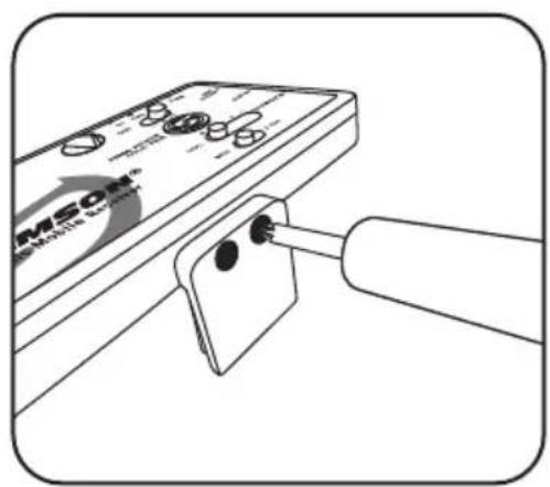
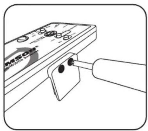
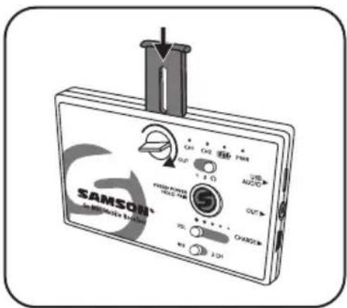
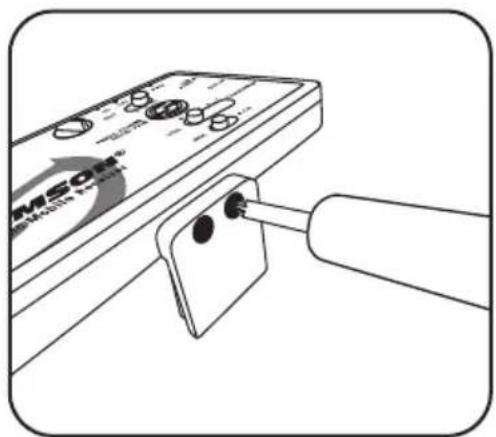
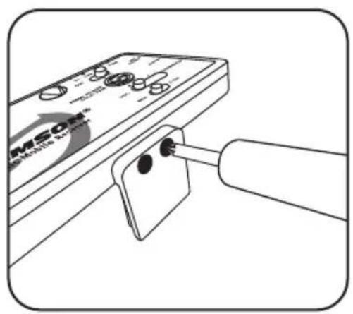
Mounting to a tablet
- Remove the Adjustable Mounting Arm by loosening the Lock Screw, sliding the arm to the closed position, then unscrew the Lock Screw completely and remove.
- Slide the mounting arm out of the receiver. Replace the Adjustable Mounting Arm with the Insert Cover piece.
- Replace the Lock Screw.
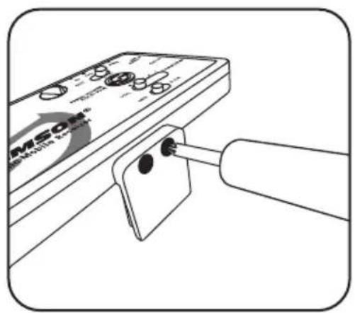
- Remove the fixed Mounting Arm by removing the two Phillips head screws.
- Affix the Large Hook-and-loop piece by peeling the adhesive backing off of the hook side and placing the Large Hook-and-loop section onto the back of the Go Mic Mobile Receiver.
- Remove the backing of the loop side and position the receiver on the rear side of the tablet.
- Press the Go Mic Mobile Receiver against the tablet to secure.
- If the Go Mic Mobile Receiver is not secure, use the additional Small Hook-and-loop section.
natural_image
Illustration of a device with ports and a connector, showing no text or symbols on the main body.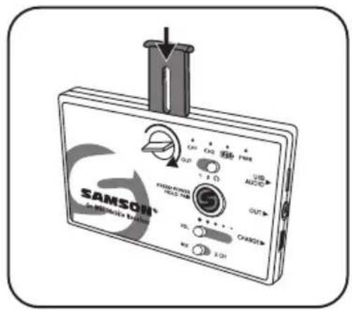
natural_image
Illustration of a handheld electronic device with a pull rod inserted, showing ports and components (no readable text or symbols)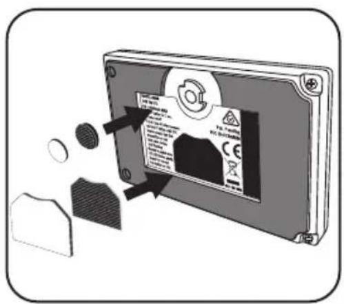
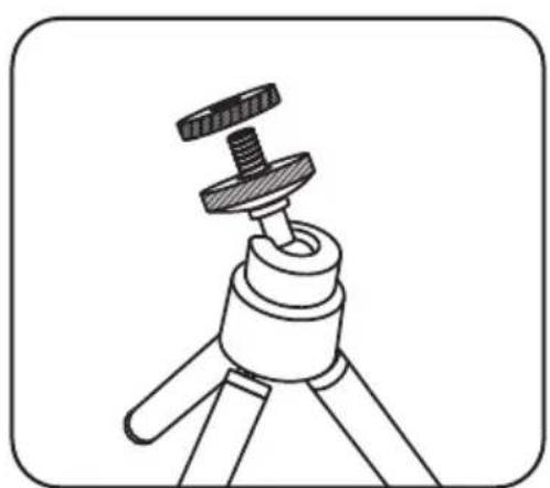
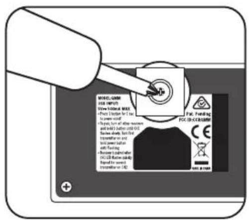
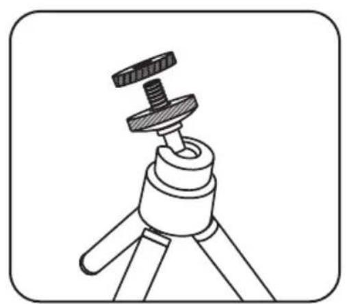
Mounting to a tripod
- Affix the 1/4"-20 Mounting Arm to the Go Mic Mobile Receiver by first removing the fixed Mounting Arm using the two Phillips head screws.
- Attach the GMM to the tripod following the tripod mounting instructions.
- If the tripod 1/4"-20 mounting stud is longer than 3/8", use the include Thumb Screw before mounting the Go Mic Mobile Receiver to the tripod.
- Mount the smartphone to the Go Mic Mobile Receiver following the instructions from the section titled "Mounting to a Smartphone".
natural_image
Line drawing of a device with a cylindrical tool inserted into a clip, showing no text or symbols on the main subject.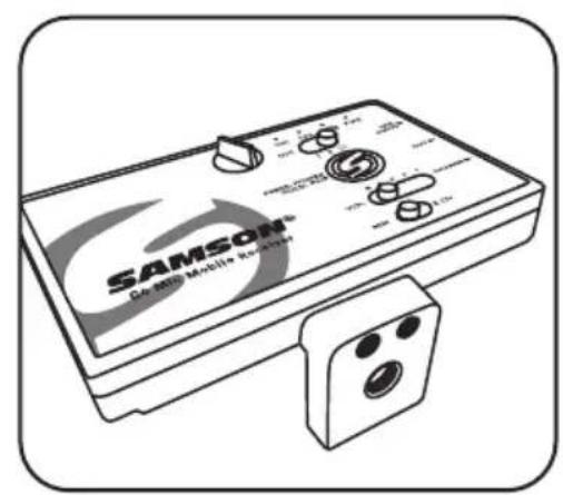
natural_image
Line drawing of a tripod-mounted device with a knob inserted (no text or symbols)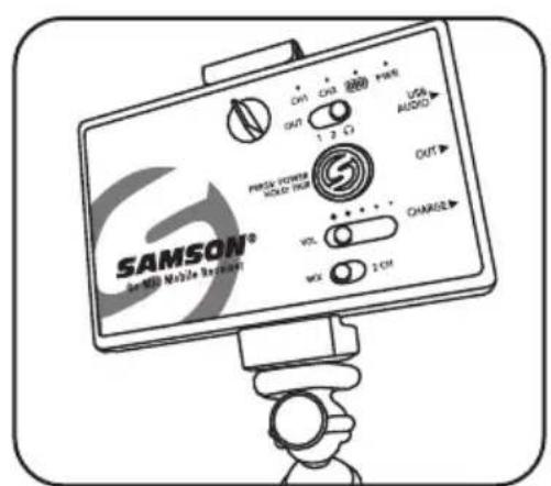
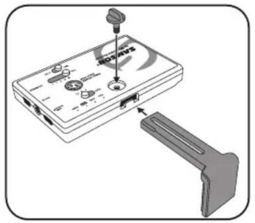
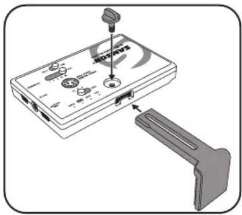
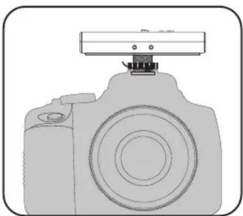
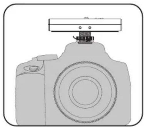
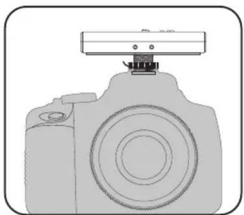
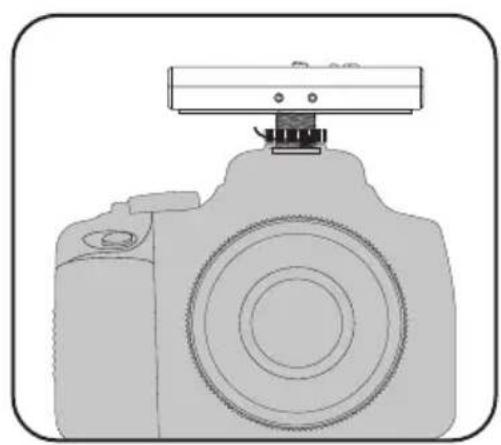
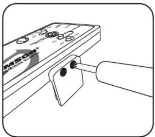
Affixing to a cold shoe adapter
- Remove the Fixed Mounting Arm by removing the two screws.
- Remove the Adjustable Mounting Arm by loosening the Lock Screw, sliding the arm to the closed position, then unscrew the Lock Screw completely and remove.
- Slide the mounting arm out of the receiver. Replace the Adjustable Mounting Arm with the Insert Cover piece.
- Replace the Lock Screw.
- Position the included shoe mount adapter on the bottom of the Go Mic Mobile Receiver, take note that the shoe mount adapter is keyed so it will stay in position when attached to the receiver.
- Using a Phillips screwdriver, fasten the shoe mount adapter to the receiver by tightening the included screw.
- Slide the GMM Receiver into the shoe mount of the connecting device.
- Once positioned, tighten the large thumb screw on the receiver shoe mount to hold in place.

natural_image
Line drawing of a DSLR camera with a mounted sensor or antenna (no text or symbols)Specifications
Go Mic Mobile Wireless System
Working Range 100' (30m) line of sight
Working Frequency 2.406 \~ 2.478 GHz
Frequency Response 10 Hz – 22 KHz
Operating Temperature -10^ +50^
Firmware Version V1.0
Hardware Version V1.0
Signal To Noise 90 dB (A) mic at minimum gain
78 dB (A) mic at maximum gain
Accessories Micro USB to Lightning cable, Micro USB to
Micro USB cable, Micro USB to USB-C cable,
Mini-B USB to USB-A cable,
3.5mm audio cable, shoe mount adapter
GMM Receiver
Max. Analog Audio Output Level +6 dBu, =4.4 Vpp, =70 mW per side into 32Ω
USB Audio Sample Rate 48 kHz
USB Audio Support Windows, Mac OS, iOS, Android, Linux
Battery Life 7 – 13 hours depending on use
Power Internal rechargeable lithium-ion battery
Operating Voltage 5V DC 500mA
HXD2 Handheld Transmitter
Microphone Type Unidirectional
RF Power <10 mW EIRP
Power Requirements Two AA (LR6) alkaline batteries
Battery Life 20 hours
PXD2 Belt Pack Transmitter
Input Connector Mini-XLR (P3)
RF Power <10 mW EIRP
Power Requirements Two AA (LR6) alkaline batteries
Battery Life 20 hours
At Samson, we are continually improving our products, therefore specifications and images are subject to change without notice.
Declaration
“Made for iPod,” “Made for iPhone,” and “Made for iPad” mean that an electronic accessory has been designed to connect specifically to iPod, iPhone, or iPad, respectively, and has been certified by the developer to meet Apple performance standards. Apple is not responsible for the operation of this device or its compliance with safety and regulatory standards. Please note that the use of this accessory with iPod, iPhone, or iPad may affect wireless performance.
iPad, iPhone, and iPod touch are trademarks of Apple Inc., registered in the U.S. and other countries. iPad Air and iPad mini are trademarks of Apple Inc.
Made for
iPhone 7 Plus, iPhone 7, iPhone SE, iPhone 6s Plus, iPhone 6s, iPhone 6 Plus, iPhone 6, iPhone 5s, iPhone 5c, iPhone 5
iPad Pro (9.7-inch), iPad Pro (12.9-inch), iPad mini 4, iPad Air 2, iPad mini 3, iPad Air, iPad mini 2, iPad mini, iPad (4th generation)
iPod touch (6th generation), iPod touch (5th generation)
natural_image
Silhouette of a person climbing a ladder inside a circular frame (no text or symbols)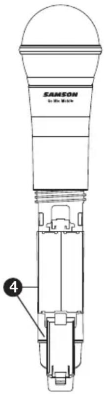
natural_image
Simple line drawing of a mechanical bracket or bracket (no text or symbols)natural_image
Simple line drawing of a rectangular object with a handle and rounded base, enclosed in a rounded square frame (no text or symbols)natural_image
Simple line drawing of a folder icon (no text or symbols)Bras de montage

natural_image
Simple line drawing of a 3D mechanical part with circular holes and a central screw (no text or symbols)natural_image
Technical illustration of a mechanical component with a flanged circular housing and threaded end (no text or symbols)natural_image
Simple 3D illustration of a circular washer or nut with a central hole, enclosed in a rounded square border (no text or symbols)Vis à ailettes
natural_image
Simple black irregular shape inside a rounded square frame (no text or symbols)natural_image
Simple black oval shape centered inside a rounded square frame (no text or symbols)natural_image
Diagram of a device with labeled ports and an attached handle, showing no readable text or symbols.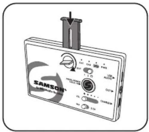
natural_image
Line drawing of a device with a plug inserted into a clip, no visible text or symbols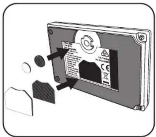
natural_image
Line drawing of a device with a cylindrical tool inserted into a clip, no visible text or symbols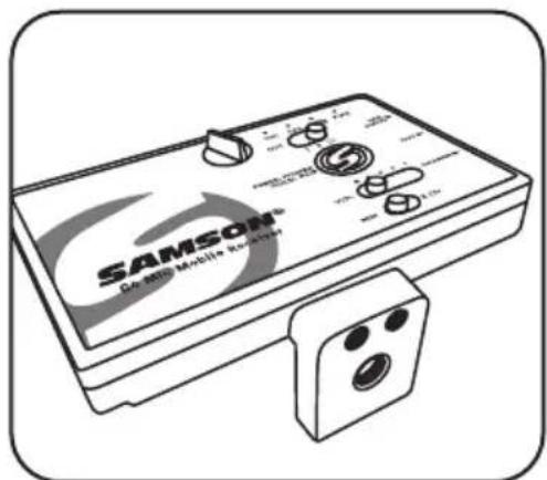
natural_image
Illustration of a Samsung Mobile controller device with control knobs and buttons (no text or symbols on the device itself)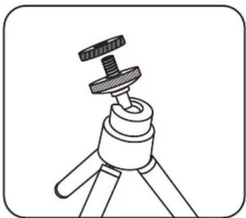
natural_image
Line drawing of a tripod-mounted camera with a flat screw and base mount (no text or symbols)
natural_image
Illustration of a medical or diagnostic device labeled 'HOTAVS' with ports and connectors, shown without any text or symbols beyond the label.
natural_image
Line drawing of a DSLR camera with a mounted sensor or antenna (no text or symbols)Spécifications
Puissance RF 10 mW EIRP
Puissance RF 10 mW EIRP
natural_image
Symbolic icon of a person climbing a ladder inside a circle (no text or symbols)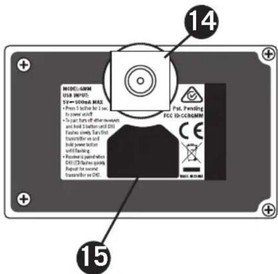
natural_image
Simple line drawing of a mechanical bracket or clip (no text or symbols)natural_image
Simple line drawing of a rectangular object with a handle and rounded base, enclosed in a rounded square frame (no text or symbols)Einschubabdeckung
natural_image
Simple line drawing of a folder icon (no text or symbols)Befestigungsstrebe
natural_image
Simple line drawing of a 3D mechanical part with circular features (no text or symbols)natural_image
Technical illustration of a mechanical component with a flanged housing and threaded shaft (no text or symbols)natural_image
Simple 3D illustration of a circular washer or nut with a central hole, enclosed in a rounded square border (no text or symbols)Flügelschraube
natural_image
Simple black irregular shape inside a rounded square frame (no text or symbols)Großes Klettstück
natural_image
Simple black oval shape centered inside a rounded square frame (no text or symbols)Kleines Klettstück
natural_image
Diagram of a device labeled 'SOTAVS' with ports and connectors, showing a mechanical attachment (no readable text or symbols beyond label)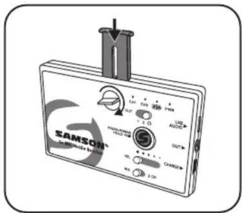
natural_image
Line drawing of a device with a cylindrical tool inserted into a clip, no visible text or symbols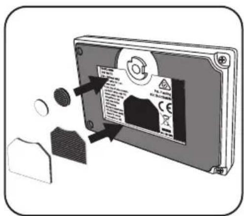
natural_image
Illustration of a handheld electronic device with a cylindrical connector inserted, showing no visible text or symbols.
natural_image
Line drawing of a Samsung Mobile Analyzer device with control knobs and buttons (no readable text or symbols)
natural_image
Line drawing of a tripod-mounted device with a knob inserted (no text or symbols)
natural_image
Diagram of a device with labeled ports and a handle, showing no readable text or symbols.
natural_image
Line drawing of a DSLR camera with a mounted sensor or antenna (no text or symbols)Technische Daten
Kabelloses Go Mic Mobile-System
Firmware-Version V1.0
Hardware-Version V1.0
natural_image
Silhouette of a person climbing a ladder inside a circular frame (no text or symbols)Leyendas del Receptor Go Mic Mobile Receiver (GMM)
Leyendas del Receptor Go Mic Mobile Receiver (GMM)
natural_image
Simple line drawing of a mechanical bracket or bracket (no text or symbols)natural_image
Simple line drawing of a mechanical component with a handle and roller (no text or symbols)Tapa
natural_image
Simple line drawing of a folder icon (no text or symbols)Brazo de montado
natural_image
Simple line drawing of a 3D mechanical part with three circular holes (no text or symbols)Brazo de montado 1/4"-20
natural_image
Isometric illustration of a mechanical component with a flanged circular feature and a rectangular plate (no text or symbols)Adaptador de zapata
natural_image
Simple 3D illustration of a circular wash or washer with a central hole, enclosed in a rounded square border (no text or symbols)Tuerca
natural_image
Simple black irregular shape on white background, enclosed in a rounded square frame (no text or symbols)natural_image
Simple black oval shape centered inside a rounded square (no text or symbols)natural_image
Illustration of a device with labeled ports and a cable connector (no text or symbols)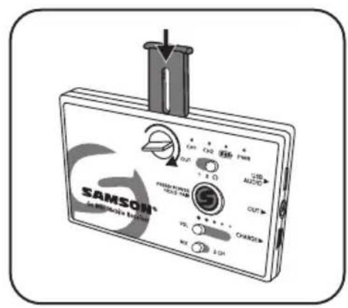
natural_image
Illustration of a device with a cylindrical tool inserted into a slot, showing no visible text or symbols.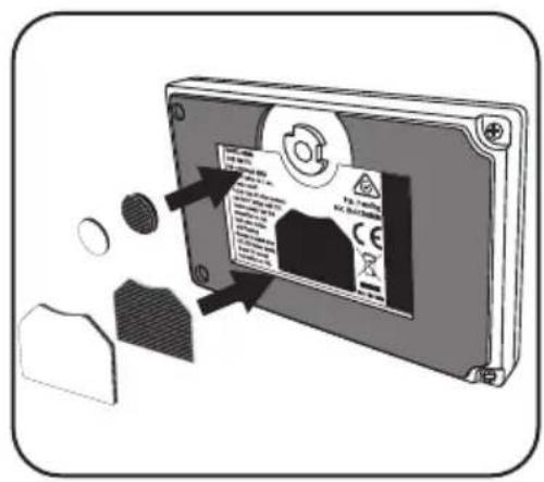
natural_image
Illustration of a handheld electronic device with a cylindrical connector inserted, showing no visible text or symbols.
natural_image
Line drawing of a Samsung Mobile Analyzer device with control knobs and buttons (no readable text or symbols)
natural_image
Line drawing of a tripod-mounted device with a knob inserted (no text or symbols)
natural_image
Illustration of a medical or diagnostic device with ports and a connector, no visible text or symbols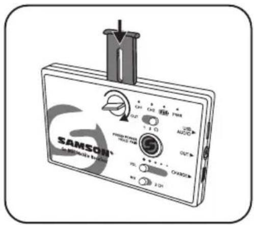
natural_image
Line drawing of a DSLR camera with a mounted sensor or antenna (no text or symbols)Especificaciones
RF Power <10 mW EIRP
natural_image
Symbolic illustration of a worker assembling a ladder inside a circle (no text or symbols)
natural_image
Simple line drawing of a mechanical bracket or bracket (no text or symbols)natural_image
Simple line drawing of a rectangular object with a handle and rounded base, enclosed in a rounded square frame (no text or symbols)Coperchio
natural_image
Simple line drawing of a folder icon (no text or symbols)natural_image
Simple line drawing of a rectangular mechanical component with circular holes and a central oval (no text or symbols)natural_image
Technical illustration of a mechanical component with a flanged housing and threaded shaft (no text or symbols)natural_image
Simple 3D illustration of a circular washer or nut with a central hole, enclosed in a rounded square border (no text or symbols)Vite ad alette

natural_image
Simple black irregular shape inside a rounded square frame (no text or symbols)Velcro grande

natural_image
Simple black oval shape centered inside a rounded square frame (no text or symbols)Velcro piccolo
Montaggio su tablet
natural_image
Diagram of a device with ports and a connector, showing no text or symbols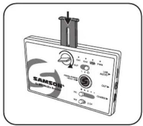
natural_image
Illustration of a handheld electronic device with a cylindrical connector inserted, showing no visible text or symbols.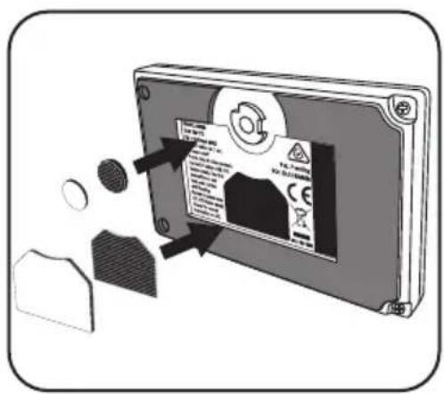
natural_image
Illustration of a handheld electronic device with a cylindrical connector inserted, showing no visible text or symbols.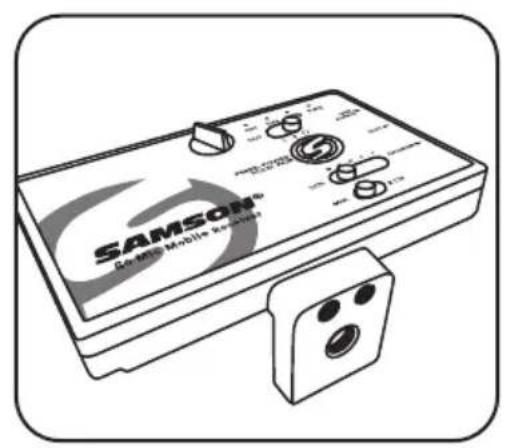
natural_image
Line drawing of a tripod-mounted device with a central knob and handle (no text or symbols)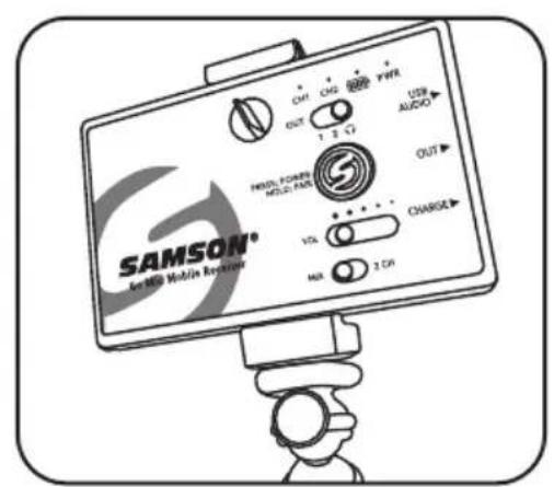
natural_image
Illustration of a medical or diagnostic device with ports and a connector, no visible text or symbols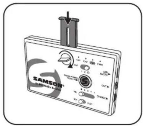
natural_image
Line drawing of a DSLR camera with a mounted sensor or antenna (no text or symbols)Specifiche tecniche
Sistema wireless Go Mic Mobile
Copyright 2020, Samson Technologies Corp. v6
Samson Technologies Corp.
278-B Duffy Ave
Hicksville, NY 11801
www.samsontech.com
natural_image
Symbolic illustration of a person climbing a ladder inside a circle (no text or symbols)
natural_image
Simple line drawing of a mechanical bracket or bracket (no text or symbols)natural_image
Simple line drawing of a rectangular object with a handle and rounded base, enclosed in a rounded square frame (no text or symbols)Wkładana pokrywa

natural_image
Simple line drawing of a folder icon (no text or symbols)Ramię montażowe
natural_image
Simple line drawing of a rectangular mechanical component with circular holes and a central oval (no text or symbols)natural_image
Technical illustration of a mechanical component with a flanged housing and threaded shaft (no text or symbols)Adapter obrotowy
natural_image
Simple 3D illustration of a circular washer or nut with a central bore, enclosed in a rounded square border (no text or symbols)Nakrętka

natural_image
Simple black irregular shape inside a rounded square frame (no text or symbols)Duży hak i pętla
natural_image
Simple black oval shape centered inside a rounded square frame (no text or symbols)Mały haczyk i pętla
Montaż do tabletu
natural_image
Diagram of a wireless device labeled 'HOTAVS' with ports and connectors, showing no readable text or symbols beyond the label.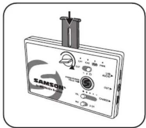
natural_image
Line drawing of a device with a probe inserted into a clip, no visible text or symbols
Montaż na statywie
natural_image
Line drawing of a handheld electronic device with a cable inserted, showing no text or symbols on the device itself.
natural_image
Line drawing of a tripod-mounted device with a knob inserted (no text or symbols)
natural_image
Illustration of a medical or diagnostic device with ports and a connector, no visible text or symbols
natural_image
Line drawing of a camera with a mounted sensor or antenna (no text or symbols)Dane techniczne
HAVING TROUBLE WITH YOUR SATELLITE? WE CAN HELP!

Contact our support team: support@samsontech.com Our experts can help you resolve any issues.
Follow us:


@samson @samsontech @samson_technologies
- Important Safety Information
- ATTENTION RISQUE D'ÉLECTROCUTION ! NE PAS OUVRIR !
- WARNING
- FCC Notice
- FCC Statement
- RF Exposure Statement (SAR)
- Introduction
- Charging the Go Mic Mobile Receiver Battery
- Getting the most out of the rechargeable battery:
- Go Mic Mobile Receiver (GMM) Callouts
- Adjustable Mounting
- HXD2 Handheld Transmitter Callouts
- PXD2 Belt Pack Transmitter Callouts
- Getting Started - Pairing
- Getting Started - Audio Connections
- Connecting to an iOS device (iPhone, iPad or iPod Touch)
- Connecting to an Android device with the digital audio output
- Connecting to a mobile device with the analog audio output
- Connecting to a DSLR, cinema camera, or mixer
- Monitoring with the Go Mic Mobile
- Getting Started - Setting the system volume
- MIX / 2 CH Switch
- Go Mic Mobile Mounting Instructions
- Mounting Accessories
- Mounting to a smartphone
- Mounting to a tablet
- Mounting to a tripod
- Affixing to a cold shoe adapter
- Specifications
- Go Mic Mobile Wireless System
- GMM Receiver
- HXD2 Handheld Transmitter
- PXD2 Belt Pack Transmitter
- Declaration
- Spécifications
- Technische Daten
- Kabelloses Go Mic Mobile-System
- Leyendas del Receptor Go Mic Mobile Receiver (GMM)
- Especificaciones
- Montaggio su tablet
- Specifiche tecniche
- Sistema wireless Go Mic Mobile
- Montaż do tabletu
- Montaż na statywie
- Dane techniczne
- HAVING TROUBLE WITH YOUR SATELLITE? WE CAN HELP!
Brand : SAMSON
Model : Go Mic Mobile HXD2
Category : Microphone