
Concert 88 Camera - Microphone SAMSON - Free user manual and instructions
Find the device manual for free Concert 88 Camera SAMSON in PDF.
| Product Type | UHF Wireless Microphone System (Concert 88) |
| Brand and Model | Samson Concert 88 Camera |
| CR88 Receiver - Dimensions (W x D x H) | 8.25" x 2.44" x 1.75" (21 x 6.2 x 4.4 cm) |
| CR88 Receiver - Weight | Not specified (approximately 0.5 kg) |
| CB88 Bodypack Transmitter - Dimensions (H x W x D) | 3.75" x 2.44" x 0.75" (9.5 x 6.2 x 1.9 cm) |
| CH88 Handheld Transmitter - Dimensions (H x Ø) | 10.23" x 2.1" (26 x 5.4 cm) |
| CH88 Handheld Transmitter - Weight | 218 g (0.48 lb) |
| Receiver Power Supply | 15 V DC / 200 mA power adapter |
| Transmitter Power Supply | 2 AA alkaline batteries (LR6) |
| Battery Life (Transmitters) | Up to 8 hours with alkaline batteries |
| Range | Up to 100 m (300 ft) line of sight |
| Frequency Response | 50 Hz – 15 kHz |
| Total Harmonic Distortion (THD) | < 1% (at 1 kHz, RF 46 dBu) |
| Dynamic Range | > 100 dB (A-weighted) |
| Signal-to-Noise Ratio | > 90 dB |
| Number of Channels | 16 (UHF) |
| Main Features | True Diversity technology, infrared sync, Tone key and Auto-mute, input gain adjustment, LED status and peak indicator |
| Maintenance and Cleaning | Clean with a dry cloth. Do not expose to water or humidity. |
| Safety | Do not open the housing. Have repairs carried out by qualified personnel. Follow safety instructions (unplug during storms, do not block ventilation). |
| Spare Parts and Repairability | No user-serviceable parts. For any repairs, contact Samson or an authorized distributor. |
| General Information | Complies with FCC Part 15 Class B. Suitable for office or home use. Recycling: do not dispose of with household waste. |
Frequently Asked Questions - Concert 88 Camera SAMSON
User questions about Concert 88 Camera SAMSON
0 question about this device. Answer the ones you know or ask your own.
Ask a new question about this device
Download the instructions for your Microphone in PDF format for free! Find your manual Concert 88 Camera - SAMSON and take your electronic device back in hand. On this page are published all the documents necessary for the use of your device. Concert 88 Camera by SAMSON.
USER MANUAL Concert 88 Camera SAMSON
natural_image
Line drawing of a wireless device with two speakers and a control panel (no text or symbols)OWNER'S MANUAL
Copyright 2015, Samson Technologies Corp.
v4.3
Samson Technologies Corp.
45 Gilpin Ave
Hauppauge, NY 11788
www.samsontech.com
Important Safety Information

ATTENTION RISQUE D'ÉLECTROCUTION ! NE PAS OUVRIR !
CAUTION: TO REDUCE THE RISK OF ELECTRIC SHOCK, DO NOT REMOVE COVER (OR BACK). NO USER-SERVICEABLE PARTS INSIDE. REFER SERVICING TO QUALIFIED SERVICE PERSONNEL.
This lightning flash with arrowhead symbol within an equilateral triangle is intended to alert the user to the presence of non-insulated “dangerous voltage” within the product’s enclosure that may be of sufficient magnitude to constitute a risk of electric shock.

The exclamation point within an equilateral triangle is intended to alert the user to the presence of important operating and maintenance instructions in the literature accompanying the appliance.
WARNING
TO PREVENT FIRE OR SHOCK HAZARD. DO NOT USE THIS PLUG WITH AN EXTENSION CORD, RECEPTACLE OR OTHER OUTLET UNLESS THE BLADES CAN BE FULLY INSERTED TO PREVENT BLADE EXPOSURE. TO PREVENT FIRE OR SHOCK HAZARD. DO NOT EXPOSE THIS APPLIANCE TO RAIN OR MOISTURE. TO PREVENT ELECTRICAL SHOCK, MATCH WIDE BLADE PLUG TO WIDE SLOT AND FULLY INSERT.
THIS DEVICE COMPLIES WITH PART 15 OF THE FCC RULES CLASS B. OPERATION IS SUBJECT TO THE FOLLOWING TWO CONDITIONS: (1) THIS DEVICE MUST NOT CAUSE HARMFUL INTERFERENCE, AND (2) THIS DEVICE MUST ACCEPT ANY INTERFERENCE RECEIVED INCLUDING INTERFERENCE THAT MAY CAUSE UNDESIRED OPERATION. SUITABLE FOR HOME OR OFFICE USE.
If you want to dispose this product, do not mix it with general household waste. There is a separate collection system for used electronic products in accordance with legislation that requires proper treatment, recovery and recycling.
Private household in the 28 member states of the EU, in Switzerland and Norway may return their used electronic products free of charge to designated collection facilities or to a retailer (if you purchase a similar new one).
For Countries not mentioned above, please contact your local authorities for a correct method of disposal.
By doing so you will ensure that your disposed product undergoes the necessary treatment, recovery and recycling and thus prevent potential negative effects on the environment and human health.
Important Safety Information
- Read these instructions.
- Keep these instructions.
- Heed all warnings.
- Follow all instructions.
- Do not use this apparatus near water.
- Clean only with dry cloth.
- Do not block any ventilation openings. Install in accordance with the manufacturer's instructions.
- Do not install near any heat sources such as radiators, heat registers, stoves, or other apparatus (including amplifiers) that produce heat.
- Do not defeat the safety purpose of the polarized or grounding type plug. A polarized plug has two blades with one wider than the other. A grounding type plug has two blades and a third grounding prong. The wide blade or the third prong are provided for your safety. If the provided plug does not fit into your outlet, consult an electrician for replacement of the obsolete outlet.
- Protect the power cord from being walked on or pinched particularly at the plugs, convenience receptacles, and at the point where they exit from the apparatus.
- Only use attachments/accessories specified by the manufacturer.
-
Use only with the cart, stand, tripod, bracket, or table specified by the manufacturer, or sold with the apparatus. When a cart is used, use caution when moving the cart/apparatus combination to avoid injury from tip-over.
-
Unplug the apparatus during lightening storms, or when unused for long periods of time.
- Refer all servicing to qualified personnel. Service is required when the apparatus has been damaged in any way, such as power supply cord or plug is damaged, liquid has been spilled or objects have fallen into the apparatus has been exposed to rain or moisture, does not operate normally, or has been dropped.
- This appliance shall not be exposed to dripping or splashing water and that no object filled with liquid such as vases shall be placed on the apparatus.
- Caution-to prevent electrical shock, match wide blade plug wide slot fully insert.
- Please keep a good ventilation environment around the entire unit.
- The direct plug-in adapter is used as disconnect device, the disconnect device shall remain readily operable.
- Batteries (battery pack or batteries installed) shall not be exposed to excessive heat such as sunshine, fire or the like.

natural_image
Symbolic illustration of a person climbing a ladder inside a circle (no text or symbols)Table of Contents
Introduction. 6
System Features. 7
System Components 7
Guided Tour - CR88 Receiver 8
Guided Tour - CB88 Belt Pack Transmitter . . . . . . . . . . . . . 10
Guided Tour - CH88 Handheld Transmitter . . . . . . . . . . . . . . 12
Quick Start - Single System Setup . . . . . . . . . . . . . . . . . . . . . . . . . 13
Quick Start - Multiple System Setup . . . . . . . . . . . . . . . . . . . . . . . . 17
Rack Mounting .....19
Concert 88 Channel Plans . . . . . . . . . . . . . . . . . . . . . . . . . . . . . . . . . . . . . . . . . . . . . . . . . . . . . . . . . . . . . . . . . . . 20
Troubleshooting . . . . . . . . . . . . . . . . . . . . . . . . . . . . . . . . . . . . . . . . . . . . . . . . . 21
Specifications. 22
Introduction
Congratulations on purchasing the Samson Concert 88 wireless system. The Concert 88 is the ideal solution for the active performer who needs a reliable, great sounding system for wireless applications. Featuring simple operation, with 16 available channels and infrared set for the transmitter channel, the Concert 88 can quickly be up and running out of the box. The Concert 88 system ensures clear, interruption-free performance by combining tone-key with auto-mute. This configuration allows only the transmitter's audio to pass through the receiver, and mutes the output if there is any interference.
The Concert 88 comes in four configurations. The vocal handheld system includes the CH88 handheld transmitter and dynamic microphone capsule. The CB88 belt pack system can be configured with either the HS5 headset microphone, LM5 lava-lier microphone, or a 14 " instrument cable. For travel or permanent installation, the Concert 88 includes a standard 19" rackmount kit.
In these pages, you'll find a detailed description of the features of the Concert 88 wireless system, as well as a guided tour through its control panel, step-by-step instructions for its setup and use, and full specifications. If your wireless system was purchased in the United States, you'll also find a warranty card enclosed—don't forget to fill it out and mail it in so that you can receive online technical support and so that we can send you updated information about this and other Samson products in the future. Also, be sure to check out our website (www.samsontech.com) for complete information about our full product line.
We recommend you keep the following records for reference, as well as a copy of your sales receipt.
Receiver Serial number: ____
Transmitter Serial number: ____
Date of purchase: ____
Dealer name: ____
With proper care and maintenance, your Concert 88 wireless system will operate trouble-free for many years. Should your wireless system ever require servicing, a Return Authorization (RA) number must be obtained before shipping your unit to Samson. Without this number, the unit will not be accepted. Please call Samson at 1-800-3SAMSON (1-800-372-6766) for an RA number prior to shipping your unit. Please retain the original packing materials and, if possible, return the unit in its original carton. If your Concert 88 system was purchased outside of the United States, contact your local distributor for warranty details and service information.
System Features
- Professional wireless system for use in both live sound and sound contracting applications
- True diversity technology maximizes active range (up to 300 feet) and reduces potential interference
- 16 available channels operating in the UHF band designed for maximum system compatibility in the same location without interference
- The CR88 receiver is a half-rack unit that can be used freestanding or can be mounted in any standard 19" rack using the included rack kit, making it easy to integrate into any traveling or fixed installation audio system
- Tone-key and auto-mute ensures clear, interruption-free performance allowing only the transmitter's audio to pass through the receiver, and mutes the output if there is any interference
- Up to eight hours of battery life, using two standard AA batteries
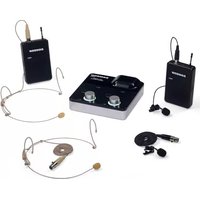
System Components
All systems
CR88 receiver
Power Supply
14 " to 14 " audio cable
Rack Accessories Long rack ear, short rack ear, two receiver adaptor
Owner's Manual
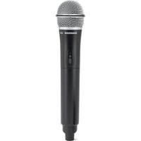
Handheld system
CH88 handheld transmitter with dynamic microphone capsule
Headset system
CB88 belt pack transmitter
HS5 headset microphone with mini-XLR connector
Lavalier System
CB88 belt pack transmitter
LM5 lavalier microphone with mini-XLR connector
Tie clip
Instrument System
CB88 belt pack transmitter
14 " to mini-XLR instrument cable
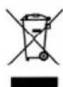
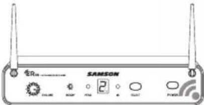
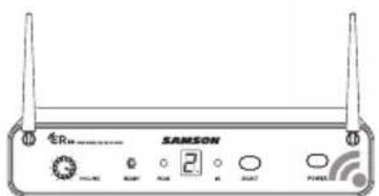
Guided Tour - CR88 Receiver
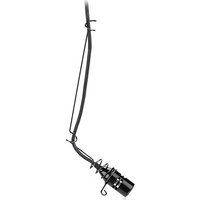
- Antennas - The antenna mountings allow full rotation for optimum placement. In normal operation, both antennas should be placed in a vertical position. Both antennas can be folded inward for convenience when transporting the CR88.
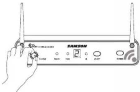
- VOLUME Control - This knob sets the level of the audio signal being output through both the balanced and unbalanced output jacks on the rear panel. Reference level is obtained when the knob is turned fully clockwise (to its "10" setting).
- READY Indicator - This indicator lights green when the CR88 is receiving RF signal and the system is ready to use.
- PEAK Indicator - This indicator lights red when the transmitted audio signal is overloaded.
- LED Display - The 7-segment LED display shows the receiver's current operating channel. The CR88 channels are indicated by O-9 and A-F.
- IR Transmitter - During "IR SET" an infrared light is used to set the transmitter channel.
- SELECT Button - Press this button to cycle through the receiver's operating channels. Press and hold this button to send the channel information to the transmitter via infrared transmission.
- POWER Switch - Use this to turn the CR88 power on and off.
Guided Tour - CR88 Receiver
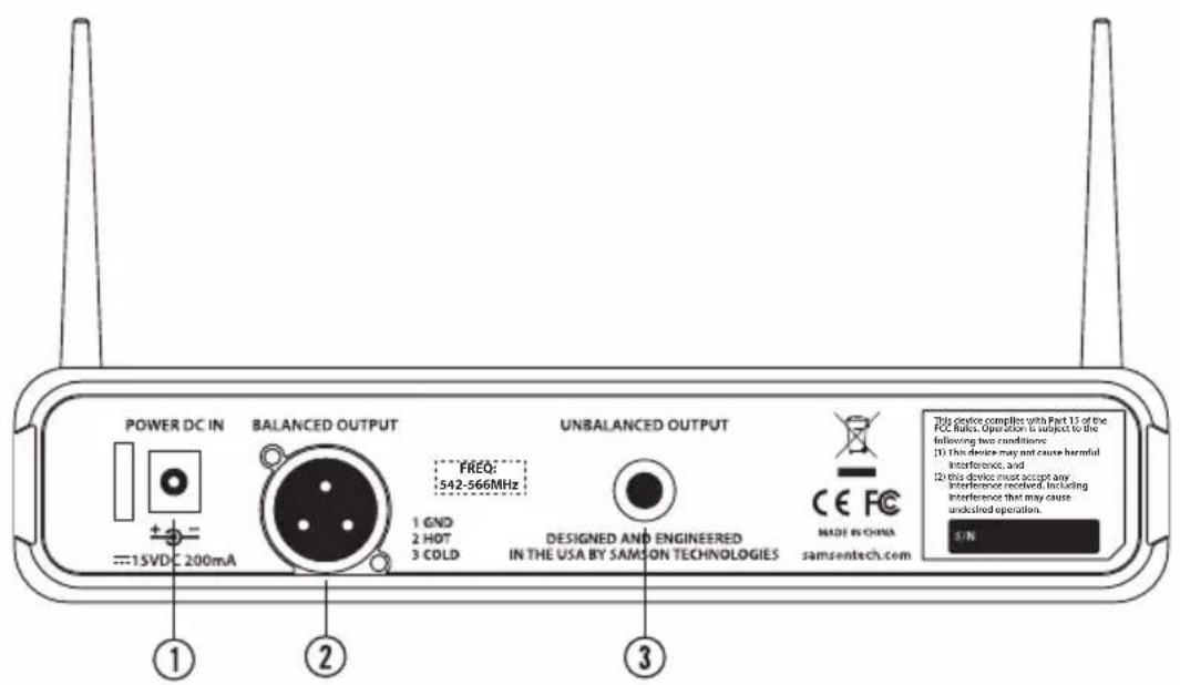
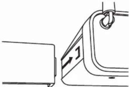
- DC Input - Connect the supplied power adapter here, using the strain relief as shown in the illustration below. WARNING: Do not substitute any other kind of power adapter. Doing so can cause severe damage to the CR88 and will void your warranty.
- BALANCED OUTPUT - Use this electronically balanced low impedance (600 Ohm) XLR jack when connecting the CR88 to professional (+4dBu) audio equipment. Pin wiring is as follows: Pin 1 ground, Pin 2 high (hot), and Pin 3 low (cold).
- UNBALANCED OUTPUT - Use this unbalanced high impedance (5K Ohm) 14 " jack when connecting the CR88 to consumer (-10dBV) audio equipment. Wiring is as follows: tip hot, sleeve ground.
natural_image
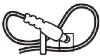
Simple line drawing of a plug inserted into a socket (no text or symbols)Using the strain relief: Gather up a loop of wire and pass it through the strain relief, then pass the adapter plug through the loop in order to create a knot.
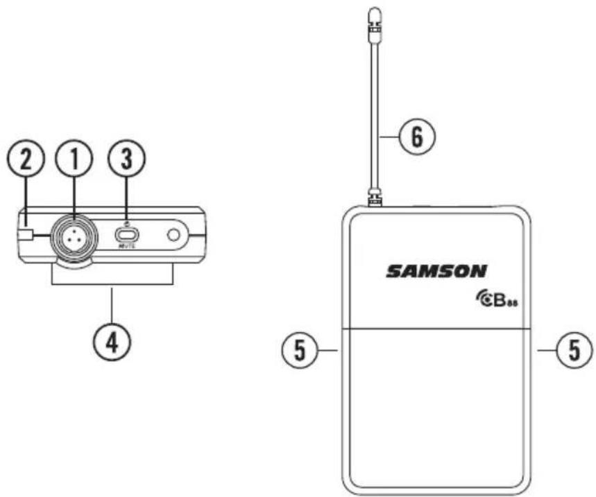
Guided Tour - CB88 Belt Pack Transmitter
-
Input Connector - Connect the input device via the mini-XLR connector. The CB88 is supplied with either a lavalier, headset microphone or 14 instrument cable.
-
Status Indicator - This LED displays the operation mode:
| GREEN Normal Operation | |
| RED Mute | |
| Flashing GREEN Low Battery | |
-
Power/Mute Switch - Press and hold to turn the unit on or off. Press and release to mute or unmute the transmitter.
-
Belt Clip - Use this clip to fasten the CB88 transmitter to a belt or guitar strap.
-
Battery Cover Release - Push in both sides and pull back to open the CB88 battery cover.
-
Antenna - This permanently attached transmitter antenna should be fully extended during normal operation.
Guided Tour - CB88 Belt Pack Transmitter
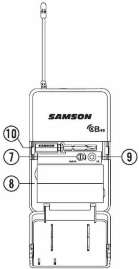
- Input GAIN Control - This control adjusts the transmitter input sensitivity to work with microphone and instruments inputs. For optimal performance, using the included screwdriver, set the input GAIN control to where you see the CR88 PEAK indicator start to light under high levels, then turn down slowly until the PEAK light stops lighting.
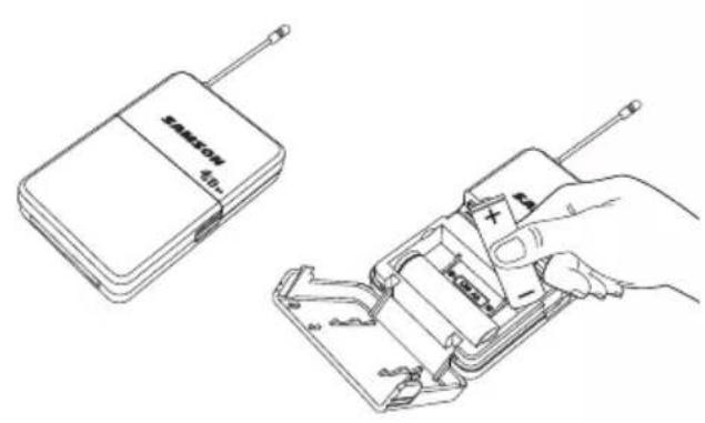
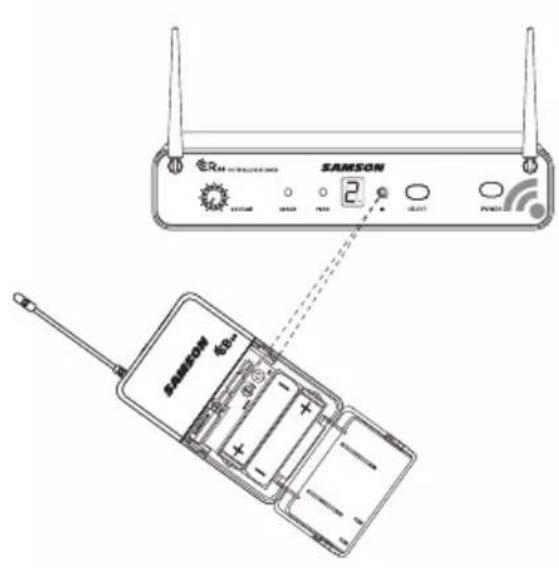
- Battery Holder - Insert two standard AA (LR6) batteries here, being sure to observe the plus and minus polarity markings shown. Although rechargeable Ni-Cad batteries can be used, they do not supply adequate current for more than four hours. WARNING: Do not insert the batteries backwards; doing so can cause severe damage to the CB88 and will void your warranty.
- IR Lens - This window is used to capture the infrared signal sent from the CR88 during the IR SET to channelize the transmitter.
- Plastic Screwdriver - Designed for use in adjusting the CB88 input GAIN (#7) control.
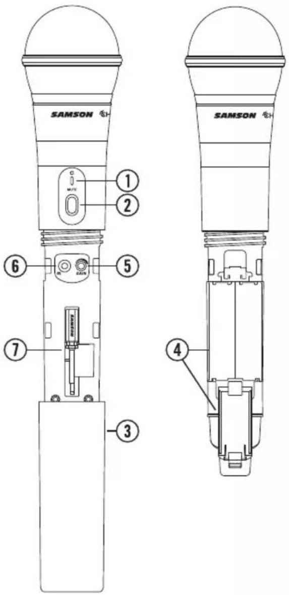
Guided Tour - CH88 Handheld Transmitter
- Status Indicator - This LED displays the operation mode:
| GREEN Normal Operation | |
| RED Mute | |
| Flashing GREEN Low Battery | |
-
Power/Mute Switch - Press and hold to turn the unit on or off. Press and release to mute or unmute the transmitter.
-
Battery Cover - Unscrew the battery cover and slide down to open the CH88 battery compartment.
-
Battery Holder - Open the battery holder by pressing the tab and lifting the cover. Insert two standard AA (LR6) batteries here, being sure to observe the plus and minus polarity markings shown. Although rechargeable Ni-Cad batteries can be used, they do not supply adequate current for more than four hours. WARNING: Do not insert the batteries backwards; doing so can cause severe damage to the CH88 and will void your warranty.
-
Input GAIN Control - This control adjusts the transmitter input sensitivity. For optimal performance, using the included
screwdriver, set the input GAIN control to where you see the CR88 PEAK indicator start to light under high levels, then turn down until the PEAK light stops lighting.
-
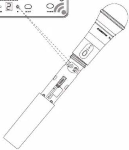
IR Lens - This window is used to capture the infrared signal sent from the CR88 during the IR SET to channelize the transmitter. The battery cover must be open and the IR Lens facing towards the receiver to load the selected channel.
-
Plastic Screwdriver - Designed for use in adjusting the CB88 input GAIN control (See #5 Input GAIN Control HH).
Quick Start - Single System Setup
In order for your wireless system to work correctly, both the receiver and transmitter must be set to the same channel.
Follow this basic procedure for setting up and using your Concert 88 wireless system:
Physically place the CR88 receiver where it will be used, and extend the antennas vertically. The general rule of thumb is to maintain “line of sight” between the receiver and transmitter so that the person using or wearing the transmitter can see the receiver.
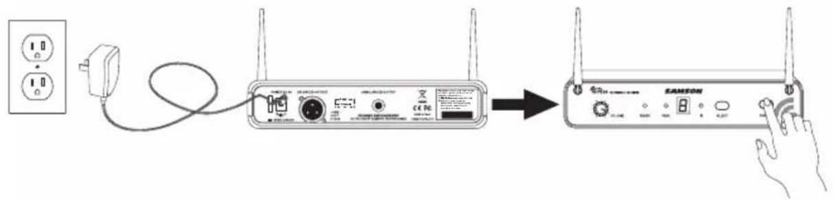
With the CR88 powered off, connect the included power adapter. Turn the CR88 on momentarily to confirm that the unit is receiving power. You'll see the LED display light up. Then turn the CR88 power off.
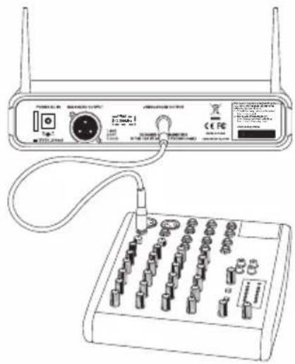
With your amplifier or mixer off and volume control all the way down, connect the CR88 receiver output jack to the mic or line level input of a mixer or amplifier using the balanced XLR output or unbalanced 14 " line level output. Turn the Level knob on the CR88 completely counterclockwise, then turn its power on.
Quick Start - Single System Setup
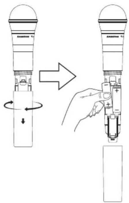
With the transmitter powered off, install two fresh AA batteries into the CB88 belt pack or CH88 handheld transmitter. Leave the battery compartment open.
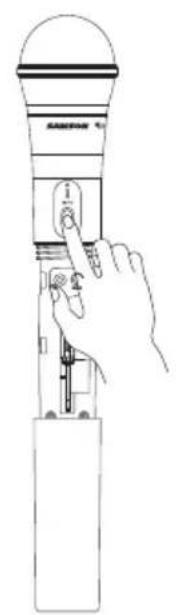
Turn on the power to the transmitter by pressing and holding Power switch; the indicator LED will light green.
natural_image
Line drawing of a hand holding a handheld device with a dial and scroll (no text or symbols)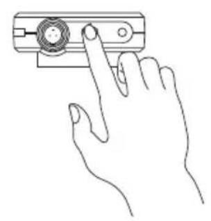
natural_image
Line drawing of a hand pressing a button on a device (no text or symbols)Quick Start - Single System Setup
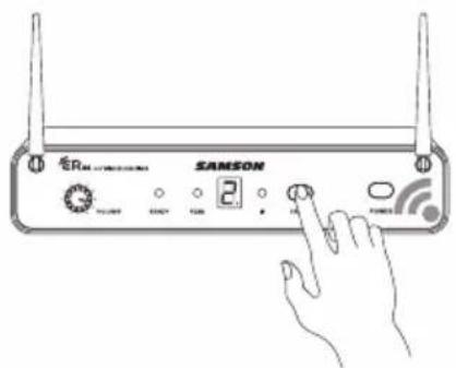
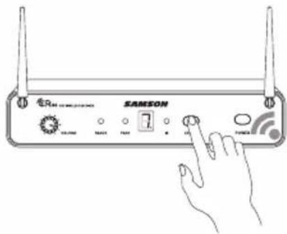
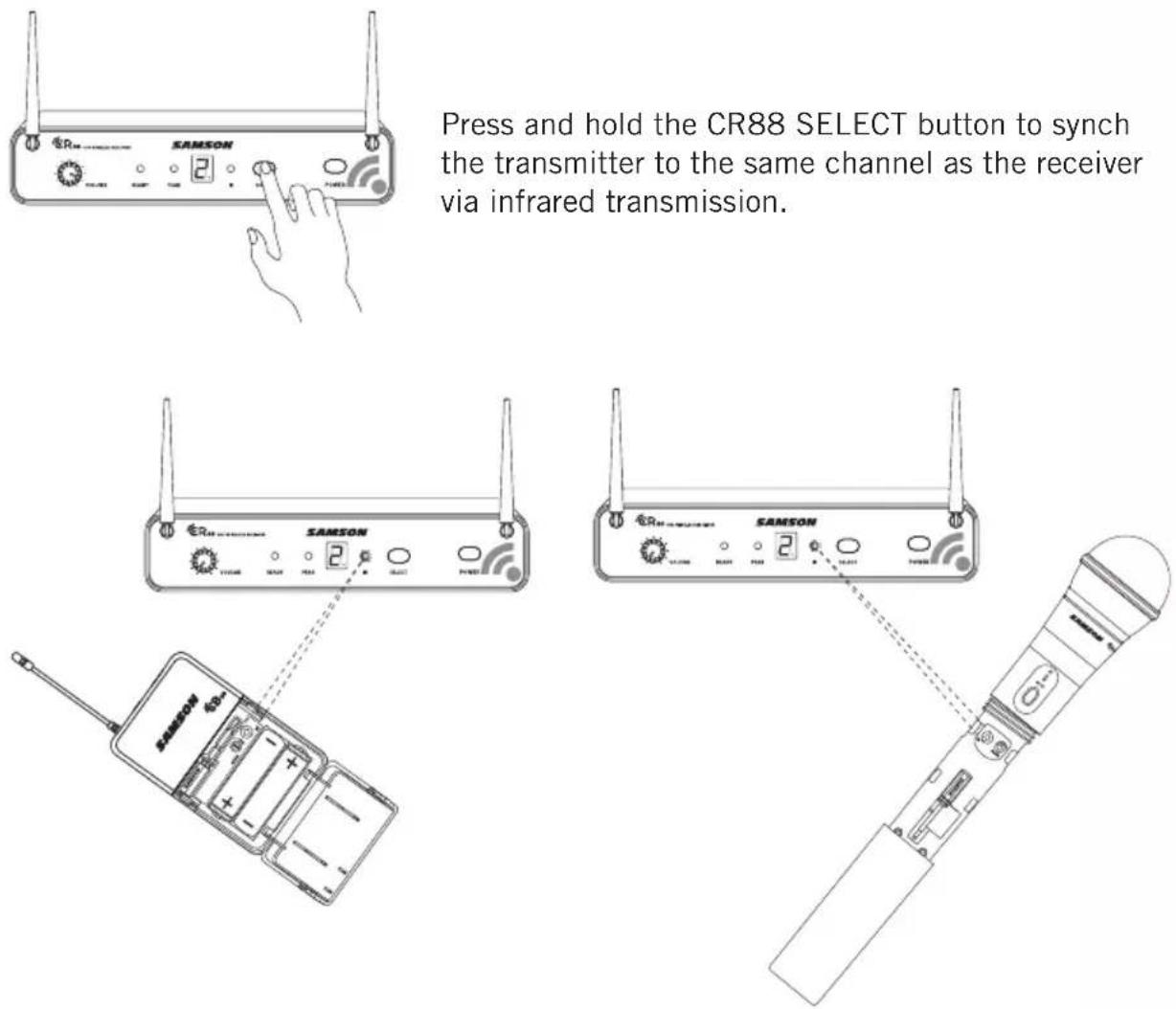
Press the SELECT button on the front of the CR88 receiver to choose an available channel. The channel number will increase by one digit, from 0-9 then A-F. Once the last channel has been reached, the count will cycle back to 0.
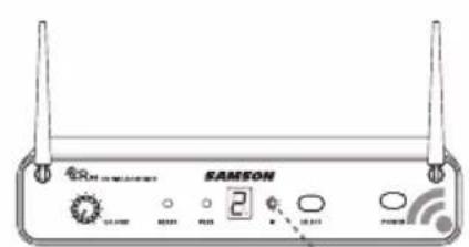
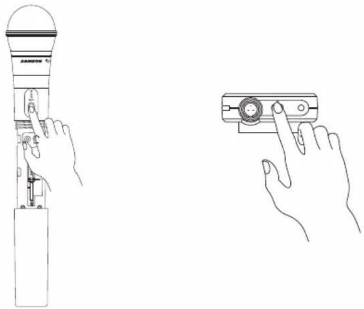
Position the transmitter about 6-12" (15-30 cm) from the front of the CR88 with the transmitter's IR window facing the IR transmitter on the front panel of the CR88 receiver.
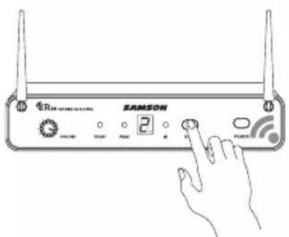
Press and hold the CR88 SELECT button to set the transmitter to the same channel as the receiver via infrared transmission
natural_image
Line drawing of a handheld device with internal components and an external control panel (no text or symbols)Quick Start - Single System Setup
When the transmission is complete, the CR88 will receive RF signal and the tone key from the transmitter. The READY indicator will light on the front panel of the CR88 receiver.
Turn on your connected amplifier or mixer, but keep the volume all the way down. Set the Volume knob on the CR88 fully clockwise (to its “10” setting). This is unity gain.
Speak or sing into the microphone, or if you are using the transmitter with a connected instrument, play the instrument at normal performance level. Slowly raise the volume of your amplifier or mixer until the desired level is reached.
If you find the system has noticeable dropouts, reduced overall working range, or unexpected noise bursts, change the operating channel of the system using the steps above.
Quick Start - Multiple System Setup
When using multiple systems, each system must be set to a different operating channel. Transmitter and receiver pairs must be on the same channel plan in order to work together (See "Concert 88 Channel Plans" on page 20).
When setting an additional transmitter, make sure to close all other transmitter battery compartments to ensure that the IR Lens is covered.
To change the operating channel of a system, press the SELECT button on the front of the CR88 receiver. The channel number will increase by one digit, from 0-9 then A-F. Once the last channel has been reached, the count will cycle back to 0.
Turn on the power to the transmitter by pressing and holding the Power switch; the indicator LED will light green.
natural_image
Line drawing of a hand operating a ZAMSON device with a close-up view of its control panel (no text or symbols present)Quick Start - Multiple System Setup
Position the transmitter about 6-12" (15-30 cm) from the front of the CR88 with the transmitter's IR window facing the receiver's IR transmitter.
Press and hold the CR88 SELECT button to synch the transmitter to the same channel as the receiver via infrared transmission.
When the transmission is complete, and the CR88 is receiving RF signal from the transmitter, the READY indicator will light on the front panel of the CR88 receiver.
If you find the system has noticeable dropouts, reduced overall working range, or unexpected noise bursts, change the operating channel of the system using the steps above.
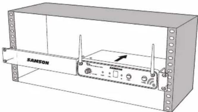
Rack Mounting
The CR88 receiver can be installed into a standard 19" rack for transport or permanent installation using the included rack ears. Follow the simple steps below to mount the CR88:
Attach the included rack ears by sliding each rack ear into the groove on either side of the CR88 until they lock into place, and the receiver flush with the front panel.
natural_image
Diagram showing a mechanical component with a bracket and attached hook, no text or symbols presentPosition the CR88 receiver into an available rack space and slide in until the rack ears are touching the rails of the rack case and are aligned with the rack rail holes.
natural_image
Technical line drawing of a SAMSON wireless device enclosure with no visible text or symbols on the device itself.Mount the receiver into the rack using the appropriate size rack screws (not included). To ensure equal tension and balance when installing the receiver, you should secure screws in a crisscross pattern of opposite corners: top left -> bottom right -> top right -> bottom left.
In order to mount two CR88 receivers in one rack space, the system includes a center connection piece. Slide the center connection piece into the groove of each receiver and attach the short rack ears to each receiver. Mount the receivers into the rack using the crisscross pattern described above.
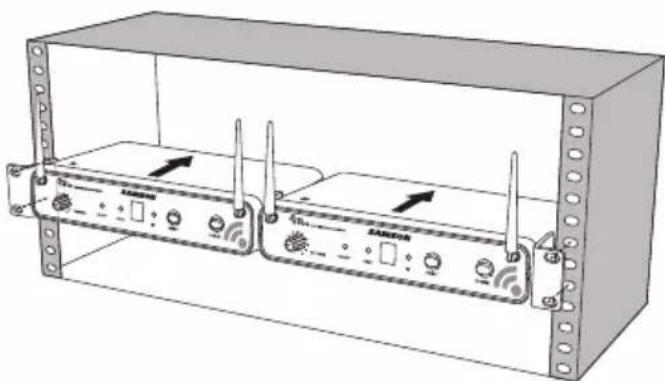
natural_image
Technical line drawing of a server rack unit with two connected modules and ventilation slots (no text or symbols)Concert 88 Channel Plans
| Group A*925-938 MHz | Group B*806-809 MHz | Group C638-662 MHz | Group D542-566 MHz | Group F*606-630 MHz | Group G*863-865 MHz | ||||||
| Ch | Freq Ch Freq | Ch | Freq Ch Freq | Ch | Freq Ch Freq | ||||||
| 0 | 925.125 0 | 806. | 125 0 638 | .125 | 0 542.125 | 0 60 | 6.125 0 863.050 | ||||
| 1 | 925.850 1 | 806. | 375 1 639 | .625 | 1 543.625 | 1 60 | 7.625 1 863.250 | ||||
| 2 | 926.575 2 | 807. | 125 2 641 | .050 | 2 545.05 | 2 609 | .05 2 863.50 | ||||
| 3 | 927.300 3 | 807. | 750 3 642 | .425 | 3 546.425 | 3 61 | 0.425 3 863.750 | ||||
| 4 | 928.025 4 | 809. | 000 4 642 | .900 | 4 546.900 | 4 61 | 0.900 4 864.050 | ||||
| 5 | 928.750 5 | 809. | 500 5 645 | .525 | 5 549.525 | 5 61 | 3.525 5 864.250 | ||||
| 6 | 929.475 6 | 806. | 250 6 647 | .100 | 6 551.100 | 6 61 | 5.100 6 864.550 | ||||
| 7 | 930.200 7 | 806. | 500 7 648 | .475 | 7 552.475 | 7 61 | 6.475 7 864.750 | ||||
| 8 | 932.300 8 | 807. | 000 8 650 | .000 | 8 554.000 | 8 61 | 8.000 8 864.950 | ||||
| 9 | 933.000 9 | 807. | 875 9 652 | .075 | 9 556.075 | 9 62 | 0.075 | ||||
| A | 933.725 A | 808. | 500 A 654 | .975 | A 558.975 | A 62 | 2.975 | ||||
| B | 934.450 B | 808. | 875 B 655 | .975 | B 559.975 | B 62 | 3.975 | ||||
| C | 935.175 C | 806. | 625 C 657 | .050 | C 561.050 | C 62 | 5.050 | ||||
| D | 935.900 D | 806. | 875 D 658 | .975 | D 562.975 | D 62 | 6.975 | ||||
| E | 936.625 E | 807. | 375 E 660 | .425 | E 564.425 | E 62 | 8.425 | ||||
| F | 937.350 F | 808. | 25 F 661.9 | .75 F | 565.975 F | 629. | 975 | ||||
* Not for use in the USA and Canada. For questions regarding available channels in your area contact your local Samson distributor.
Troubleshooting
| Issue Solutions | |
| No Audio | Make sure that the transmitter and receiver are both powered on. |
| Ensure the transmitter's batteries are installed correctly. | |
| Check that the transmitter is not muted. | |
| Confirm that the CR88 adaptor is correctly connected and plugged into an electrical outlet. | |
| Turn on the CR88 receiver. | |
| Make sure the CR88 audio output connections are securely connected. | |
| Ensure that the receiver and transmitter are in line of sight with one another. | |
| Check the receiver and audio input device level controls. | |
| Ensure that the transmitter and receiver are set to the same operating channel. If unsure, reset the channel by performing an IR set. | |
| Distorted Audio | The receiver output level or audio input device level may be too high. |
| Check the transmitters batteries, and replace if low. | |
| The input gain on the transmitter (CB88) or audio source level may be too high. | |
| Audio Dropout | The transmitter may be too far away from the receiver. Move it closer to the receiver, or reposition the antennas. |
| Remove any sources that may cause RF interference such as cell phones, cordless phones, lighting equipment, computers, metal structures, etc. | |
| Receiver will not power on | Check the adaptor to ensure it is properly connected and plugged into an outlet providing power. |
| Transmitter will not power on (LED lights RED) | Replace the transmitter batteries. |
| Unwanted noise or interference | If using multiple systems, make sure none of the systems are operating on the same channel. If the problem persists, change one or all of the systems channels. |
Specifications
System
Working Range 300' (100m) line of sight
Audio Frequency Response 50 Hz - 15 kHz
T.H.D. (Overall) <1% (@AF 1 kHz, RF 46 dBu)
Dynamic Range >100 dB A-weighted
Signal to Noise >90 dB
Operating Temperature -10^ (14°F) to +60^ (+140°F)
Tone Key Frequency 32.768 kHz
CB88 Belt pack Transmitter
Input Connector Mini-XLR (P3)
Input Impedance 1MΩ
Input Gain Range 38 dB
RF Power 10 mW EIRP
Power Requirements Two AA (LR6) alkaline batteries
Battery Life 8 hours
Dimensions (HxLxD) 3.75" x 2.44" x 0.75"
96mm x 62mm x 18.5mm Weight 0.2 lb / 93 g
CH88 Handheld Transmitter
Microphone Element Dynamic
Input Gain Range 28 dB
RF Power 10 mW EIRP
Power Requirements Two AA (LR6) alkaline batteries
Battery Life 8 hours
Dimensions (Hx∅) 10.23" x 2.1"
260mm x 54mm
Weight 0.48 lb / 218 g
CR88 Receiver
Audio Output Level - Unbalanced +14 dBu
Audio Output Level - Balanced +9 dBu
Audio Output Impedance - Unbalanced 810 Ohms
Audio Output Impedance - Balanced 240 Ohms
Sensitivity -100 dBm / 30 dB sinad
Image Rejection >50 dB
Operating Voltage 15 VDC 200mA
Dimensions (LxWxH) 8.25" x 4.9" x 1.75"
210mm x 125mm x 44mm
Weight 0.85 lb / 388 g
At Samson, we are continually improving our products, therefore specifications and images are subject to change without notice.
FCC Rules and Regulations
Samson wireless receivers are certified under FCC Rules part 15 and transmitters are certified under FCC Rules part 74.
Licensing of Samson equipment is the user's responsibility and licensability depends on the user's classification, application and frequency selected.
NOTE: This equipment has been tested and found to comply with the limits for a Class B digital device, pursuant to Part 15 of the FCC Rules. These limits are designed to provide reasonable protection against harmful interference in a residential installation. This equipment generates, uses and can radiate radio frequency energy and, if not installed and used in accordance with the instructions, may cause harmful interference to radio communications. However, there is no guarantee that interference will not occur in a particular installation. If this equipment does cause harmful interference to radio or television reception, which can be determined by turning the equipment off and on, the user is encouraged to try to correct the interference by one or more of the following measures:
- Reorient or relocate the receiving antenna.
- Increase the separation between the equipment and receiver.
- Connect the equipment into an outlet on a circuit different from that to which the receiver is connected.
- Consult the dealer or an experienced Radio/TV technician for help.
WARNING: Changes or modifications not expressly approved by the party responsible for compliance could void the user's authority to operate the equipment.
This device complies with RSS-210 of Industry & Science Canada.
Operation is subject to the following two conditions:
(1) this device may not cause harmful interference and (2) this device must accept any interference received, including interference that may cause undesired operation.
This equipment is intended for use in wireless microphone applications.
Equipment is intended for sale in: AT, BE, CH, CY, CZ*, DK, EE, FI*, FR*, DE*, GR*, HU, IE, IS, IT, LV, LT*, LU, MT*, NL, NO*, PL* PT, RO, SK, SI, ES, SE, UK
*Subject to license. Please contact your national frequency authority for information on available legal use in your area. Any changes or modifications not expressly approved by Samson Technologies Corp. could void your authority to operate the equipment.
Hereby, Samson Technologies Corp., declares that this CR88, CH88, CB88 is in compliance with the essential requirements and other relevant provisions of Directive 1999/5/EC. The declaration of conformity may be consulted at
http://www.samsontech.com/site_media/support/manuals/Concert_88_DOC.pdf
C€1797①
natural_image
Silhouette of a person climbing a ladder inside a circle (no text or symbols)Table des matières
Introduction. 27
natural_image
Simple line drawing of a cable with a plug inserted, no text or symbols present
natural_image
Line drawing of two hands operating a handheld device, one pointing at the button and the other holding the screen (no text or symbols present)natural_image
Line drawing of two hands operating a handheld device with a circular button, no text or symbols presentnatural_image
Diagram showing a mechanical component with a bracket and attached hook, no text or symbols presentnatural_image
Technical line drawing of a SAMSON wireless device enclosure with two antennas and a central control unit (no text or symbols beyond branding)natural_image
Technical line drawing of a two-port network device enclosed in a transparent enclosure, showing ports and signal indicators (no text or labels)96mm x 62mm x 18,5mm
Poids
0.2 lb / 93 g
210mm x 125mm x 44mm
Poids
0.85 lb / 388 g
natural_image
Silhouette of a person climbing a ladder inside a circle (no text or symbols)natural_image
Simple line drawing of a cable with a plug inserted, no text or symbols presentnatural_image
Line drawing of two hands operating a handheld device, one pointing at the button and the other holding a circular connector (no text or symbols present)natural_image
Line drawing of two hands operating a ZAMSON device, one pointing at the button and the other holding the device (no text or symbols present)natural_image
Pure technical line drawing of a mechanical component with no text or symbolsnatural_image
Technical line drawing of a SAMSON wireless router enclosure with ventilation slots and indicator lights (no text or symbols on the device itself)natural_image
Technical line drawing of a two-port network device enclosed in a transparent enclosure, showing ports and signal indicators (no text or labels)Tone Key Frequenz 32.768 kHz
96mm x 62mm x 18.5mm
210mm x 125mm x 44mm
natural_image
Symbolic illustration of a person climbing a ladder inside a circle (no text or symbols)natural_image
Simple line drawing of a cable with a plug inserted into a socket (no text or symbols)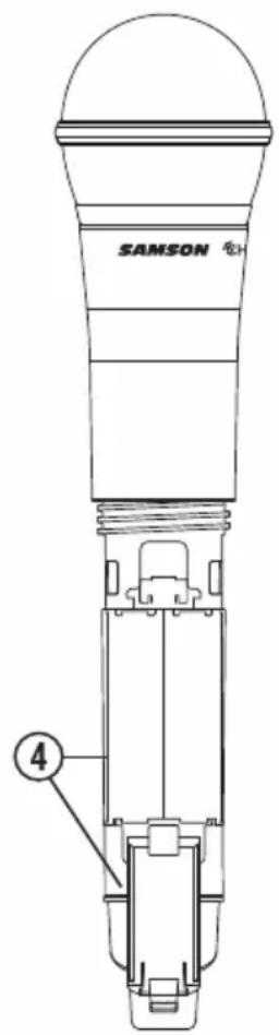
natural_image
Line drawing of two hands interacting with a device, one pointing at the button and the other holding a remote control (no text or symbols present)natural_image
Line drawing of two hands operating a device with a microphone and a control panel (no text or symbols)natural_image
Diagram showing a mechanical component with a bracket and attached hook, no text or symbols presentnatural_image
Technical line drawing of a SAMSON wireless device enclosure with two antennas and a central control panel (no text or symbols on the device itself)natural_image
Technical line drawing of a server rack unit with two connected devices and ventilation grilles (no text or symbols)Planes de Canales del Concert 88
| Group A*925-938 MHz | Group B*806-809 MHz | Group C638-662 MHz | Group D542-566 MHz | Group F*606-630 MHz | Group G*863-865 MHz | ||||||
| Canal | Frec. Canal | Frec. Canal | Frec. Canal | Canal | Frec. Canal | Frec. Canal | Frec. | ||||
| 0 925,125 | 0 806,125 | 0 638,125 | 0 542, | 125 0 606 | 125 0 | 863,050 | |||||
| 1 925,850 | 1 806,375 | 1 639,625 | 1 543, | 625 1 607 | 625 1 | 863,250 | |||||
| 2 926,575 | 2 807,125 | 2 641,050 | 2 545, | 05 2 609, | 05 2 863,550 | ||||||
| 3 927,300 | 3 807,750 | 3 642,425 | 3 546, | 425 3 610 | 425 3 | 863,750 | |||||
| 4 928,025 | 4 809,000 | 4 642,900 | 4 546, | 900 4 610 | 900 4 | 864,050 | |||||
| 5 928,750 | 5 809,500 | 5 645,525 | 5 549, | 525 5 613 | 525 5 | 864,250 | |||||
| 6 929,475 | 6 806,250 | 6 647,100 | 6 551, | 100 6 615 | 100 6 | 864,550 | |||||
| 7 930,200 | 7 806,500 | 7 648,475 | 7 552, | 475 7 616 | 475 7 | 864,750 | |||||
| 8 932,300 | 8 807,000 | 8 650,000 | 8 554, | 000 8 618 | 000 8 | 864,950 | |||||
| 9 933,000 | 9 807,875 | 9 652,075 | 9 556, | 075 9 620 | 075 | ||||||
| A 933,725 | A 808,500 | A 654,975 | A 558, | 975 A 622 | 975 | ||||||
| B 934,450 | B 808,875 | B 655,975 | B 559 | 975 B 623 | 975 | ||||||
| C 935,175 | C 806,625 | C 657,050 | C 561, | 050 C 625 | 050 | ||||||
| D 935,900 | D 806,875 | D 658,975 | D 562 | 975 D 626 | 975 | ||||||
| E 936,625 | E 807,375 | E 660,425 | E 564, | 425 E 628 | 425 | ||||||
| F 937,350 | F 808,25 F | 661,975 F | 565,975 | F 629,975 | |||||||
T.H.D. (Global) <1% (@AF 1 kHz, RF 46 dBu)
natural_image
Symbolic illustration of a person climbing a ladder inside a circle (no text or symbols)Indice
Introduzione .90
Caratteristiche del sistema. . . . . . . . . . . . . . . . . . . . . . . . . . . . . . . . . . . . . . . 91
Componenti del sistema . . . . . . . . . . . . . . . . . . . . . . . . . . . . . . . . . . . . . . . . . . . . . . . . . . 91
Tour guidato - funzioni del ricevitore CR88 . . . . . . . . . . . . . . . . . . . 92
natural_image
Simple line drawing of a plug inserted into a socket (no text or symbols)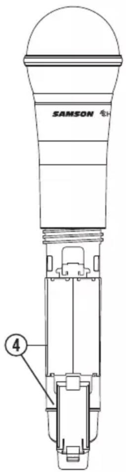
natural_image
Line drawing of two hands operating a handheld device, one pointing at the button and the other holding a circular device (no text or symbols present)natural_image
Line drawing of a hand holding a handheld device with a dial indicator (no text or symbols)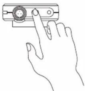
natural_image
Line drawing of a hand holding a device with a circular button on the screen (no text or symbols)natural_image
Pure technical line drawing of a mechanical component with no text or symbolsnatural_image
Technical line drawing of a SAMSON wireless router enclosure with ventilation slots and indicator lights (no text or symbols on the device itself)natural_image
Technical line drawing of a two-port network device enclosed in a transparent enclosure, showing ports and signal indicators (no text or labels)Dimensioni (H x L x P) 3,75" x 2,44" x 0,75"
96 mm x 62 mm x 18,5 mm
Peso
0,2 lb / 93 g
- Important Safety Information
- ATTENTION RISQUE D'ÉLECTROCUTION ! NE PAS OUVRIR !
- WARNING
- Table of Contents
- Introduction
- System Features
- System Components
- All systems
- Handheld system
- Headset system
- Lavalier System
- Instrument System
- Guided Tour - CR88 Receiver
- Guided Tour - CB88 Belt Pack Transmitter
- Guided Tour - CH88 Handheld Transmitter
- Quick Start - Single System Setup
- Quick Start - Multiple System Setup
- Rack Mounting
- Concert 88 Channel Plans
- Specifications
- System
- CB88 Belt pack Transmitter
- CH88 Handheld Transmitter
- CR88 Receiver
- FCC Rules and Regulations
- Table des matières
- Planes de Canales del Concert 88
- Indice
Brand : SAMSON
Model : Concert 88 Camera
Category : Microphone