Magys 500 WS - Welding machine GYS - Free user manual and instructions
Find the device manual for free Magys 500 WS GYS in PDF.
User questions about Magys 500 WS GYS
0 question about this device. Answer the ones you know or ask your own.
Ask a new question about this device
Download the instructions for your Welding machine in PDF format for free! Find your manual Magys 500 WS - GYS and take your electronic device back in hand. On this page are published all the documents necessary for the use of your device. Magys 500 WS by GYS.
USER MANUAL Magys 500 WS GYS
natural_image
Technical line drawings of two industrial testing machines with wheels and control panels (no text or symbols)FR 2-3 / 4-12 / 66-76
EN 2-3 / 13-20 / 66-76
DE 2-3 / 21-29 / 66-76
ES 2-3 / 30-38 / 66-76
RU 2-3 / 39-47 / 66-76
IT 2-3 / 48-56 / 66-76
NL 2-3 / 57-65 / 66-76
MAGYS 400-4
MAGYS 400 GR
MAGYS 500 GR
MAGYS 500 WS
FIG - 1

text_image
13 10 5 MAGYS 400 GR MAGYS 500 GR 8 x2 MAGYS 400-4 12 11 7 9 3 2 1 4 6FIG - 2

text_image
- Acier / Steel / Stahl / Acero / Staal / Aço - Inox - Stainless steel A/ Gaine acier / Steel sheath / StahlseeleB/

text_image
- Alu NO USE Tube capillaire / Capillary Pipe / Kapillarrohr Gaine téflon / Teflon sheath / TeflonseeleFIG - 3
text_image
Technical diagram showing labeled mechanical components with numbered annotationsFIG - 4

text_image
9 32.5 8 35.0 10 SYN TEST + mm MANUAL θ·m/min press 3s 2T 4T SPOT DELAY 1 OPTIMAL SYNERGIC 10 15 +1 -1 -2 -3 -4 20 +2 +3 1 m/min MANUAL SYNERGIC 8 MADE IN FRANCE 1 2 3 12 500A SYNERGIC HEAVY DUTY CYCLE 7 SYNERGIC WIRE 0,8 1,0 1,2 5 TYPE Fe (CO₂) Fe/CrNi (Ar+CO₂) Alu (Ar) 3 SPOT·DELAY -2 -3 -4 -5 -1 Auto 4FIG - 5
text_image
P1 P2 P3 R61S30 63101 R61S32 63101 R61S31 63101 P4 → R61S63 63086 R61S61 63101 P5 CN23S01 53108 0% 50% 100% Q23S03 97984 U23S01 63526 JP41P05 75028 JP41P06 75028 C11S01 63382 C11S05 63382 C11S06 63364 C52S10 63366 P051S01 64090 R52S05 63124AVERTISSEMENTS - RÈGLES DE SÉCURITÉ
CONSIGNE GÉNÉRALE

INSTALLATION - FONCTIONNEMENT PRODUIT
9- Support bobine ∅ 200/300 mm.
ANOMALIES, CAUSES, REMÈDES
Read and understand the following safety recommendations before using or servicing the unit. Any change or servicing that is not specified in the instruction manual must not be undertaken.
The manufacturer is not liable for any injury or damage caused due to non-compliance with the instructions featured in this manual. In the event of problems or uncertainties, please consult a qualified person to handle the installation properly.
ENVIRONMENT
This equipment must only be used for welding operations in accordance with the limits indicated on the descriptive panel and/or in the user manual. The operator must respect the safety precautions that apply to this type of welding. In case of inedaquate or unsafe use, the manufacturer cannot be held liable for damage or injury.
This equipment must be used and stored in a place protected from dust, acid or any other corrosive agent. Operate the machine in an open, or well-ventilated area.
Operating temperature:
Use between -10 and +40°C (+14 and +104°F).
Store between -20 and +55°C (-4 and 131°F).
Air humidity:
Lower or equal to 50% at 40°C (104°F).
Lower or equal to 90% at 20°C (68°F).
Altitude:
Up to 1000 meters above sea level (3280 feet).
PROTECTION OF THE INDIVIDUALS
Arc welding can be dangerous and can cause serious and even fatal injuries.
Welding exposes the user to dangerous heat, arc rays, electromagnetic fields, noise, gas fumes, and electrical shocks. People wearing pacemakers are advised to consult with their doctor before using this device.
To protect oneself as well as the other, ensure the following safety precautions are taken:

In order to protect you from burns and radiations, wear clothing without cuffs. These clothes must be insulated, dry, fireproof and in good condition, and cover the whole body.

Wear protective gloves which guarantee electrical and thermal insulation.

Use sufficient welding protective gear for the whole body: hood, gloves, jacket, trousers... (varies depending on the application/operation). Protect the eyes during cleaning operations. Do not operate whilst wearing contact lenses.
It may be necessary to install fireproof welding curtains to protect the area against arc rays, weld spatters and sparks.
Inform the people around the working area to never look at the arc nor the molten metal, and to wear protective clothes.

Ensure ear protection is worn by the operator if the work exceeds the authorised noise limit (the same applies to any person in the welding area).
Stay away from moving parts (e.g. engine, fan...) with hands, hair, clothes etc.
Never remove the safety covers from the cooling unit when the machine is plugged in - The manufacturer is not responsible for any accident or injury that happens as a result of not following these safety precautions.
The pieces that have just been welded are hot and may cause burns when manipulated. During maintenance work on the torch or the electrode holder, you should make sure it's cold enough and wait at least 10 minutes before any intervention. The cooling unit must be on when using a water cooled torch in order to ensure that the liquid does not cause any burns.
ALWAYS ensure the working area is left as safe and secure as possible to prevent damage or accidents.
WELDING FUMES AND GAS

The fumes, gases and dust produced during welding are hazardous. It is mandatory to ensure adequate ventilation and/or extraction to keep fumes and gases away from the work area. An air fed helmet is recommended in cases of insufficient air supply in the workplace.
Check that the air intake is in compliance with safety standards.
Care must be taken when welding in small areas, and the operator will need supervision from a safe distance. Welding certain pieces of metal containing lead, cadmium, zinc, mercury or beryllium can be extremely toxic. The user will also need to degrease the workpiece before welding. Gas cylinders must be stored in an open or ventilated area. The cylinders must be in a vertical position secured to a support or trolley. Do not weld in areas where grease or paint are stored.
FIRE AND EXPLOSION RISKS

Protect the entire welding area. Compressed gas containers and other inflammable material must be moved to a minimum safe distance of 11 meters. A fire extinguisher must be readily available.
Be careful of spatter and sparks, even through cracks. It can be the source of a fire or an explosion.
Keep people, flammable objects and containers under pressure at a safe distance.
Welding of sealed containers or closed pipes should not be undertaken, and if opened, the operator must remove any inflammable or explosive materials (oil, petrol, gas...).
Grinding operations should not be directed towards the device itself, the power supply or any flammable materials.
GAS BOTTLE

Gas leaking from the cylinder can lead to suffocation if present in high concentrations around the work area.
Transport must be done safely: Cylinders closed and product off. Always keep cylinders in an upright position securely chained to a fixed support or trolley. Close the bottle after any welding operation. Be wary of temperature changes or exposure to sunlight.
Close the bottle after any welding operation. Be wary of temperature changes or exposure to sunlight.
Cylinders should be located away from areas where they may be struck or subjected to physical damage.
Always keep gas bottles at a safe distance from arc welding or cutting operations, and any source of heat, sparks or flames.
Be careful when opening the valve on the gas bottle, it is necessary to remove the tip of the valve and make sure the gas meets your welding requirements.
ELECTRIC SAFETY

The machine must be connected to an earthed electrical supply. Use the recommended fuse size.
An electrical discharge can directly or indirectly cause serious or deadly accidents.
Do not touch any live part of the machine (inside or outside) when it is plugged in (Torches, earth cable, cables, electrodes) because they are connected to the welding circuit.
Before opening the device, it is imperative to disconnect it from the mains and wait 2 minutes, so that all the capacitors are discharged.
Do not touch the torch or electrode holder and earth clamp at the same time.
Damaged cables and torches must be changed by a qualified and skilled professional. Make sure that the cable cross section is adequate with the usage (extensions and welding cables). Always wear dry clothes in good condition, in order to be insulated from the electrical circuit. Wear insulating shoes, regardless of the environment in which you work in.
EMC CLASSIFICATION

These Class A devices are not intended to be used on a residential site where the electric current is supplied by the public network, with a low voltage power supply. There may be potential difficulties in ensuring electromagnetic compatibility on these sites, because of the interferences, as well as radio frequencies.


This equipment complies with IEC 61000-3-12, provided that the power of the short-circuit Ssc is equal to or greater than 3.9 MVA at the interface between the machine and the mains power network. It is the responsibility of the installer or user of the equipment to ensure if necessary by consulting the operator of the mains electricity, that the equipment is only connected to a power supply where the power of short-circuit ssc is equal to or greater than 3.9 MVA.
This equipment complies with the IEC 61000-3-11 standard.
ELECTROMAGNETIC INTERFERENCES

The electric currents flowing through a conductor cause electrical and magnetic fields (EMF). The welding current generates an EMF field around the welding circuit and the welding equipment.
The EMF fields may disrupt some medical implants, such as pacemakers. Protection measures should be taken for people wearing medical implants. For example, access restrictions for passers-by or an individual risk evaluation for the welders.
All welders should take the following precautions in order to minimise exposure to the electromagnetic fields (EMF) generated by the welding circuit::
- position the welding cables together – if possible, attach them;
- keep your head and torso as far as possible from the welding circuit;
- never enroll the cables around your body;
- never position your body between the welding cables. Hold both welding cables on the same side of your body;
- connect the earth clamp as close as possible to the area being welded;
- do not work too close to, do not lean and do not sit on the welding machine
- do not weld when you're carrying the welding machine or its wire feeder.

People wearing pacemakers are advised to consult their doctor before using this device.
Exposure to electromagnetic fields while welding may have other health effects which are not yet known.
RECOMMANDATIONS TO ASSES THE AREA AND WELDING INSTALLATION
Overview
The user is responsible for installing and using the arc welding equipment in accordance with the manufacturer's instructions. If electromagnetic disturbances are detected, it is the responsibility of the user of the arc welding equipment to resolve the situation with the manufacturer's technical assistance. In some cases, this remedial action may be as simple as earthing the welding circuit. In other cases, it may be necessary to construct an electromagnetic shield around the welding power source and around the entire piece by fitting input filters. In all cases, electromagnetic interferences must be reduced until they are no longer bothersome.
Welding area assessment
Before installing the machine, the user must evaluate the possible electromagnetic problems that may arise in the area where the installation is planned.
. In particular, it should consider the following:
a) the presence of other power cables (power supply cables, telephone cables, command cable, etc...) above, below and on the sides of the arc welding machine.
b) television transmitters and receivers ;
c) computers and other hardware;
d) critical safety equipment such as industrial machine protections;
e) the health and safety of the people in the area such as people with pacemakers or hearing aids;
f) calibration and measuring equipment
g)The isolation of the equipment from other machinery.
The user will have to make sure that the devices and equipments that are in the same room are compatible with each other. This may require extra precautions;
h) make sure of the exact hour when the welding and/or other operations will take place.
The surface of the area to be considered around the device depends on the building's structure and other activities that take place there. The area taken in consideration can be larger than the limits determined by the companies.
Welding area assessment
Besides the welding area, the assessment of the arc welding systems installation itself can be used to identify and resolve cases of disturbances. The assessment of emissions must include in situ measurements as specified in Article 10 of CISPR 11. In situ measurements can also be used to confirm the effectiveness of mitigation measures.
RECOMMENDATION ON METHODS OF ELECTROMAGNETIC EMISSIONS REDUCTION
a. National power grid: The arc welding machine must be connected to the national power grid in accordance with the manufacturer's recommendation. If interferences occur, it may be necessary to take additional preventive measures such as the filtering of the power supply network. Consideration should be given to shielding the power supply cable in a metal conduit. It is necessary to ensure the shielding's electrical continuity along the cable's entire length. The shielding should be connected to the welding current's source to ensure good electrical contact between the conduct and the casing of the welding current source.
b. Maintenance of the arc welding equipment: The arc welding machine should be submitted to a routine maintenance check according to the manufacturer's recommendations. All accesses, service doors and covers should be closed and properly locked when the arc welding equipment is on.. The arc welding equipment must not be modified in any way, except for the changes and settings outlined in the manufacturer's instructions. The spark gap of the arc start and arc stabilization devices must be adjusted and maintained according to the manufacturer's recommendations.
c. Welding cables: Cables must be as short as possible, close to each other and close to the ground, if not on the ground.
d. Electrical bonding : consideration should be given to bonding all metal objects in the surrounding area. However, metal objects connected to the workpiece increase the riskof electric shock if the operator touches both these metal elements and the electrode. It is necessary to insulate the operator from such metal objects.
e. Earthing of the welded part: When the part is not earthed - due to electrical safety reasons or because of its size and its location (which is the case with ship hulls or metallic building structures), the earthing of the part can, in some cases but not systematically, reduce emissions. It is preferable to avoid the earthing of parts that could increase the risk of injury to the users or damage other electrical equipment. If necessary, it is appropriate that the earthing of the part is done directly, but in some countries that do not allow such a direct connection, it is appropriate that the connection is made with a capacitor selected according to national regulations.
f. Protection and plating : The selective protection and plating of other cables and devices in the area can reduce perturbation issues. The protection of the entire welding area can be considered for specific situations.
TRANSPORT AND TRANSIT OF THE WELDING MACHINE

Do not use the cables or torch to move the machine. The welding equipment must be moved in an upright position.
Do not place/carry the unit over people or objects.
Never lift the machine while there is a gas cylinder on the support shelf. A clear path is available when moving the item.
The removal of the wire reel from the machine is recommended before undertaking any lifting operation.
The machine is fitted with handle(s) to facilitate transportation. Be careful not to underestimate the machine's weight. The handle(s) cannot be used for slinging.
Stray welding currents/voltages may destroy earth conductors, damage electrical equipment or cause components to warm up which may cause a fire.
- All welding connections must be firmly secured, check regularly!
- Check that the metal piece fixation is strong and without any electrical problems!
- Attach or hang all the electrically conductive elements, such as the trolley and slinging equipment, in order to insulate them
- Do not place any electrical equipment, such as drills or grinders, on top of the welding machine without insulating them!
- Always place welding torches or electrodes holders on an insulated surface when they're not in use!
EQUIPMENT INSTALLATION
- Put the machine on the floor (maximum incline of 10^ .)
- Ensure the work area has sufficient ventilation for welding, and that there is easy access to the control panel.
- The machine must be placed in a sheltered area away from rain or direct sunlight.
- The machine must not be used in an area with conductive metal dusts.
- The machine protection level is IP23, which means :
- Protection against access to dangerous parts from solid bodies of a ≥12.5mm diameter and,
- Protection against the rain inclined at 60% towards the vertical.
These devices can be used outside in accordance with the IP23 protection index. - Do not use the machine at temperatures >40^ .
The power cables, extensions and welding cables must be fully uncoiled to prevent overheating.

The manufacturer does not incur any responsibility regarding damages to both objects and persons that result from an incorrect and/or dangerous use of the machine.
MAINTENANCE / RECOMMENDATIONS


- Maintenance should only be carried out by a qualified person. Annual maintenance is recommended.
- Ensure the machine is unplugged from the mains, and wait for two minutes before carrying out maintenance work. DANGER High Voltage and Currents inside the machine.
- Remove the casing 2 or 3 times a year to remove any excess dust. Take this opportunity to have the electrical connections checked by a qualified person, with an insulated tool.
- Regularly check the condition of the power supply cable. If the power cable is damaged, it must be replaced by the manufacturer, its after sales service or an equally qualified person.
- Ensure the ventilation holes of the device are not blocked to allow adequate air circulation.
- Do not use this equipment to thaw pipes, to charge batteries, or to start any engine.
INSTALLATION - PRODUCT OPERATION
Only qualified personnel authorised by the manufacturer should perform the installation of the welding equipment. During the installation, the operator must ensure that the machine is disconnected from the mains.
DESCRIPTION
Magys are «synergic» semi-automatic welding units on wheels, ventilated for welding (MIG or MAG). They operate on a three-phase 400 V power supply.
To operate, the MAGYS:
- 400 GR must be used with the external wire feeder WS-4R (ref. 034723) or W5S-4L (ref 032835) and an interconnect cable.
- 500 GR must be used with the external wire feeder WS-4R (ref. 034723) or W5S-4L (ref 032835) and an interconnect cable.
- 500 WS must be used with the external wire feeder WS-4L (ref. 033573) or W5S-4L (ref 032835) and an interconnect cable.
POWER SUPPLY
This machine is fitted with a 32 A socket type EN 60309-1 which must only be used on a three-phase 400 V (50 - 60 Hz) power supply fitted with four wires and one earthed neutral.
The absorbed effective current (I1eff) is displayed on the machine, for optimal use. Check that the power supply and its protection (fuse and/or circuit breaker) are compatible with the current needed by the machine. In some countries, it may be necessary to change the plug to allow the use at maximum settings.
- The machine is designed to work on a 400V +/- 15% power supply. • It switches to protection mode if the power supply voltage is below 330V RMS or over 490V RMS.
- The start is done via an on / off switch (1 - FIG 1) set to I, and the stop is done by switching it to 0. Warning! Never disconnect the power supply while the machine is charging.
- Fan operation: The MAGYS 400-4/400 GR and 500 GR features an intelligent cooling fan system in order to minimise machine noise. The ventilation remains activated for 10 minutes and then stops automatically. If the user changes the mode by pressing the dedicated key (1 - FIG 4) it will immediately stop the cooling. It will be switched on again at the next welding bead. Same operation for the MAGYS 500 WS and its cooling system (cooling unit and fan).
CONNECTION TO A GENERATOR
The machine can work with generators as long as the auxiliary power meets the following requirements:
- The voltage must be AC, with a 400V ±15% RMS value and a peak voltage below 700V,
- The frequency must be between 50 and 60 Hz.
It is imperative to check these requirements, as many generators generate high voltage peaks that can damage these machines.
USE OF EXTENSION LEADS
All extension leads must have an adequate size and section, relative to the machine's voltage.
Use an extension lead that complies with national safety regulations.
| Current input Extension lead section (<45m) | |
| 400 V 6 mm ^2 | |
DEVICE PRESENTATION
Put the rubber mat (only for the Magys 400-4) and the four ring eyes (with their lock washers). The gas bottle needs to be fastened with 2 chains in the holes at the back of the machine. Attention: Fasten correctly the bottle. You have also holes to pass a strap on (not included).
1- On - Off switch 8- Fastening chains for bottles
2- Power settings - 2 switches with 9 positions to adjust the welding voltage output
3- Control panel – Welding settings 10-
4- European standard torch connection
5- Power cable (5 m) 12- 5.5 L tank (Magys 500 WS)
6- Earth cable 13- Chain fixing slot
7- Gas bottle support (max 1 bottle of 10 m ^3 )
9- Reel support ∅ 200/300 mm.
Gas connector (For the Magys 500 WS, the gas hose needs to be connected to the flowmeter of the bottle).
11- Water inlet and outlet (Magys 500 WS)
SEMI-AUTOMATIC WELDING FOR STEEL / STAINLESS STEEL (MAG MODE) (FIG. 2-A)
The MAGYS units are equipped originally to work on 1mm steel wire (original drive rollers ∅ 1/1.2 steel/stainless steel). Make sure that drive rollers, liner and contact tube are adapted to your wire diameter.
For Steel or Stainless Steel, you will need to use specific gas - Argon + CO2 (Ar + CO2). The proportion of CO2 will vary depending on usage. The gas flow for steel is between 15 and 25L / min depending on the environment and experience of the welder.
For wires with a diameter > 1.6 mm, it is recommended to remove the capillary tube.
SEMI-AUTOMATIC WELDING FOR ALUMINIUM (MIG MODE) (FIG. 2-B)
This welding unit can weld aluminium wires from 1mm.
To weld aluminium, neutral gas "pure Argon" (AR) is required. When choosing gas, ask a gas distributor for advice. The gas flow in aluminium should be between 20 and 25L/ min depending on the environment and experience of the welder.
Things to note when welding with Aluminium
- Set the pressure of the rollers to a minimum so as not to crush the wire
- Remove the capillary tube before connecting the aluminium torch
- When welding aluminium use a special aluminium torch with Teflon sheath to reduce friction.
Do not cut the sheath near the connector! It is used to guide the wire from the rollers. (See diagram (16))
- Contact Tip: Use the specific Aluminium contact tip corresponding to the diameter of the wire.
- Drive rollers: Use specific drive rollers to weld with aluminium wire.
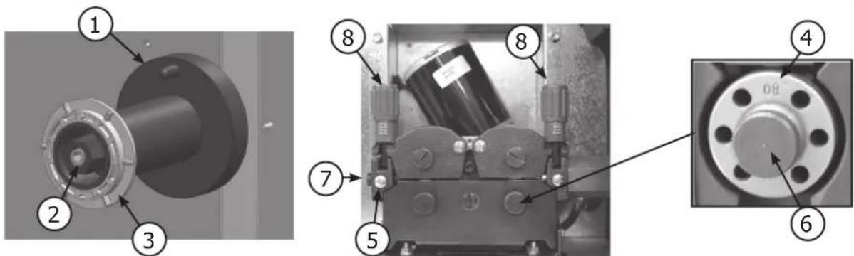
REEL AND TORCH ASSEMBLY (FIG. 3)
- Position the reel on to the support taking care of the pin (1). To use with 5kg (∅200mm) wire reels requires use of reel adaptor (ref. 042889).
- Adjust the reel break (2) to avoid the reel movement tangling the wire when welding stops. Then tighten the plastic screw (3) firmly.
- For the first use :
- Release the fixing screw of the wire guide (5)
- Place the rollers, and tighten the screws (6).
- Place the wire guide (7) as close as possible to the roller but without touching it, then tighten the fixing screw.
- To select the adjustment of the drive rollers (8), bend the wire where it comes out of the nozzle to stop it, and then start the motor. Tighten the knob whilst pressing the trigger until the wire starts to move. The setting is correct when the guide roller slides over the wire, even when it is blocked at the end of the torch.
NOTE: When the trigger is pulled and without any contact detected within 4s, the MAGYS will automatically switch to the 'fast forward' mode until the trigger is released. There is no gas during this operation.
WARNING: The 'fast forward' mode use current in the wire; avoid any contact with any metallic part around.
GAS COUPLING
Fit the regulator/flowmeter to the gas bottle, and then fit the gas pipe to the connector (see (10), FIG-2 for MAGYS 400-4). To avoid gas leaks, use the collars provided in the accessories box.
LIQUID COOLING (MAGYS 500 WS) (FIG-2) & THERMAL PROTECTION
Connect the red and blue wire of the connecting harness from the generator (11) to the separate wire feeder (see WS-4L/W5S-4L user manual)
Fill the tank (12) up to its maximum (5.5L). The cooling liquid recommended by GYS (ref. 052246), must be used. The use of any other cooling liquid, and especially the standard automobile liquid, can lead by electrolysis effect, to the accumulation of dumps in the cooling system, damaging it and even more by blocking the circuit.
Any damage caused to the machine by the use of another cooling liquid will not be taken under warranty.
The MAGYS 500 WS is not recommended to be used by an air cooled torch.
If anyway you want to use an air cooled torch, a by-pass is supplied with the unit. Connect it between the red and blue cables. If you don't respect this rule, the pump will be damaged, and the repair will not be taken under warranty.
• Always respect the basic rules of welding.
- Do not block/cover the ventilation holes of the machine.
- Leave the device plugged in after welding to allow proper cooling down.
- Thermal protection: The LED(8) switches on when the unit is on safety mode. The cooling time (forced ventilation) is by cycle of 10 minutes for the 400-4 and 20 minutes (forced ventilation + pump) for the MAGYS 400 GR/500 GR/500 WS depending on the external temperature.
- Ventilation: the fan is only active during the welding and the cooling cycles.
CONTROL PANEL (FIG-4)
Welding mode selection / test:
- 2T: two-stage welding / 4T: four-stage welding.
- SPOT: Spot welding with adjustable spot diameter
- Delay: intermittent welding modes for an optimised operating procedure
Access to the hidden mode and Expert mode setting (see next page)
③ SPOT / DELAY potentiometer: To adjust the welding time of a point, the size of the point and the time between each point.
4 Arc dynamics potentiometer: To adjust automatically or manually the arc dynamics.
⑤ Metal selection and manual mode: Read chapter «Welding unit settings»
⑥ Mode « Synergic »: Read chapter « Welding unit settings »
⑦ Wire diameter: Select the wire diameter used.
⑧ Thermal protection LED: Read chapter «Thermal protection».
⑨ Voltage display: By pulling the trigger (The LED ○V indicates that your torch is on) the voltage will be displayed according to the parameters selected.
⑫ Power adjustment switch: 20 positions for the Magys 400-4, 400 GR and 30 for the 500 GR / 500 WS.
Wire speed setting: Potentiometer to adjust the wire speed. The speed can vary from 1 to 24 m/minute.
Note for the MAGYS 400 GR/500 GR/500 WS: It is possible to select either the potentiometer of the separate wire feeder or the generator.
See chapter «wire speed potentiometer» and the sticker inside the wire feeder
Welding current display ⑩: indicates the amperage (LED « A ») or the thickness ⑪ recommended according to the power
⑩ selected (read « test » function in the chapter « welding unit settings »).
⑪ Note: « NOP » on the display indicates that the welding current selected is superior to the one recommended taking into account the parameters (type and diameter of the wire).
WELDING UNIT SETTINGS (FIG-4)
« SYNERGIC » MODE
This function automatically controls the wire speed. There is no need to set the wire speed manually.
- Position the potentiometer (2) in the middle of the « Optimal synergic » zone
- Select: Wire type (5), wire diameter (7), power mode (with the 2 power switches on the front (12)).
From the settings chosen, the unit determines the optimum wire speed and is ready to weld. It is also possible to manually adjust the wire speed (+ or -) if necessary using the potentiometer (2). The last welding configuration is saved in the memory automatically (wire diameter, wire type, mode).
Only in the synergic mode, I will indicate you the thickness you can weld with the parameters selected without using any gas or wire. These values are calculated on the basis of a welding on the flat surface. Attention: you have current in the torch, so avoid any contact with any metallic part.
NOTE: If the gas, the wire diameter, and the metal used are different from the ones selected in the synergic mode, you will need to switch to the manual mode to set up the welding unit.
«MANUAL » MODE
To set your device, proceed as follows:
- Choose the welding voltage using the 2 power switches according to the thickness to weld.
- Adjust the wire speed using the potentiometer (12).
MANUAL
8→m/min
When in manual this function displays the wire speed setting on display (10).
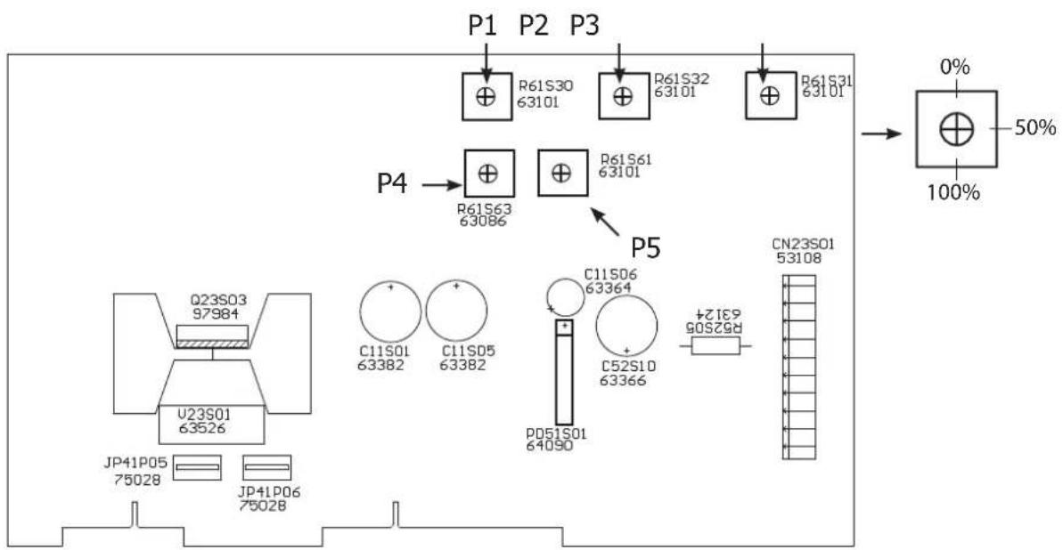
MODIFICATION OF THE ORIGINAL PARAMETERS (FIG-4)
The device controls the arcing speed, the burn back and the post gaz. These parameters are set up in the factory, but it is possible to modify them directly on the circuit board. Attention: this intervention must be done by a qualified electrician.
IMPORTANT: Make sure the product is not connected to the power supply before any intervention

text_image
0% 50% (Factory setting) 100%P1: Set up the arcing speed to have a smooth start in order to avoid any spatter with the first short circuit.
P2: Set up the Burn back to avoid the sticking of the wire on the contact tube.
P3: The setting up of the Post gas will regulate the time of gas used after the welding to protect it.
EXPERT SETTING (ACCORDING TO STANDARD EN 1090)
In order to meet the EN 1090 standard, it is possible to calibrate the voltage, the current and the wire speed of this product. Warning: the calibration must be done by GYS or the distributor where they have a qualified maintenance department using the correct equipment: resistive load (ref: 060135), tachometer (ref: 053953), voltmeter and ammeter (ref: 053984).
1/ Calibration of voltage and current (FIG-5):
The potentiometers P4 (voltage) and P5 (current) are adjustable directly on the electronic board.
2/ Calibration of the wire speed (FIG-4):
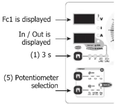
To access this mode, you need to press key (1) for 3 seconds. Then, press key (1) 3 times to display «Fc3». Now, you can calibrate your wire speed to more or less 10% by step of 1% with keys (5) and (7). To exit this mode, press key (1), the display shows «END».
HIDDEN MODE PARAMETERS (FIG-4)
The hidden mode allows you to set the following parameters:
- Gouging mode (only for Magys 500 GR / 500 WS) «Fc0»
- Selection of the wire speed potentiometer (only for Magys 400 GR / 500 GR / 500 WS) «Fc1»
- Metal Selection «Fc2»
- Calibration of the wire speed (see above: expert settings) «Fc3»
To enter this mode, press and hold button 1 for 3 sec. The machine will display « Fc0 », « OFF ». Press button 1 again to enter Gouging mode.
Gouging mode: (only for Magys 500 GR / 500 WS) (Fc0)
ATTENTION: once the power generator is activated, the output current is available on the unit. Do not put the torch on the floor or in contact with any metallic part. Always wear protective clothing.
To deactivate the power generator push button 5. To leave Gouging mode and hidden mode, push button 1 and the screen will display « END ».
Gouging process:
- Turn the voltage switch to maximum,
- Open the cylinder valve or compressed air network,
- Contact between the electrode and the metal piece will create a circuit. The intense heat will melt the workpiece and air will pass through the arc quickly enough to blow the molten material away.
- Conversely to the MMA process, the work is done by pushing the arc.
The visible length of the electrode must between 100 and 150 mm.
The torch is connected to the back of the generator, on the + terminal for steel and stainless steel electrodes. For copper electrodes you can use any terminal. For Nickel electrodes connect the electrode holder to the - terminal. The earth clamp is connected to the other terminal.
Always follow the instructions as indicated on the electrode packaging.
Protective clothing should always be worn when gouging!
Selection of the wire speed: (only for the Magys 400 GR/500 GR/500 WS) (Fc1)
Wire speed can be adjusted using wire feeder potentiometer or generator potentiometer. Only one potentiometer can be active at a time.
On this type of equipment with separate wire feeder, 2 wire speed potentiometers are available.
You can choose to use between both but they can't be activated at the same time.
To enter into « Selection of the wire speed potentiometer » mode push button 1 for 3 seconds and then press the same button again. The top screen will display « Fc1 » and the bottom one:
- « Out » for the separate wire feeder potentiometer
To choose between Out and In, press button 5. Press button 1 to leave this mode and enter another mode.
flowchart
graph TD
    A["Fc1 is displayed"] --> B["Block V"]
    C["In / Out is displayed"] --> D["Block A"]
    E["(1) 3 s"] --> F["Block P"]
    G["(5) Potentiometer selection"] --> H["Block R"]
    I["Block S"] --> J["Block T"]
Metal selection (Fc2)
This mode will allow you to select or de-select a specified combination of 3 types of metal (Fe CO ^2 , FeCrNi ArCO ^2 , Aluminium). To enter this mode, follow the instruction to enter hidden mode and press button 1 twice. The screen will display « Fc2 ». In order to choose the combination of metal (8 selections available), press button 5 until you reach the combination required. The « Manual » position can't be deactivated.
RISK OF INJURY DUE TO MOVING PARTS

The wire feeders contain moving parts that may catch hands, hair, clothes or tools and lead to injuries!
- Do not touch rotating / moving / feeding parts of the machine!
- Make sure that all panels remain closed when in use!
- Do not wear gloves when setting up the wire and changing the wire reel.
TROUBLESHOOTING
| SYMPTOMS POSSIBLE CAUSES REMEDIES | ||
| The welding wire speed is not constant. | Debris is blocking up the opening. | Clean out the contact tip or change it and replace the anti-adherence product. Ref. 041806 |
| The wire skids in the rollers. | ·Check the roller pressure or replace it. ·Wire diameter incompatible with roller ·Covering wire guide in the torch incompatible. | |
| The rollers slide over the wire Check and tighten | the roller's screws. | |
| The wire-feeder motor doesn't operate. | Reel or roller brake too tight. Adjust the brake and rollers. | |
| Electrical supply problem. | Check that the power switch is in the "On" position. | |
| Bad wire feed. | Covering wire guide dirty or damaged. Clean or replace | |
| Reel brake too tight Adjust the brake | ||
| No welding current | Bad connection to the main supply. | Check the mains connection and ensure the supply is 400 V (3PH). |
| Bad earth connection. | Check the earth cable (connection and clamp condition). | |
| Torch trigger inoperative. Check the torch trigger / replace torch | ||
| The wire jams (after the rollers) | Guide wire sheath crushed. Check the sheath and torch body. | |
| Wire jammed in the torch Clean or replace. | ||
| No capillary tube. Check the presence of capillary tube. | ||
| Wire speed too fast Reduce the wire speed | ||
| The welding bead is porous | The gas flow rate is not sufficient. | Adjust flow range 15 to 25 L / min. Clean the work-piece. |
| Gas bottle empty. Replace | ||
| Gas quality unsatisfactory. Replace | ||
| Air flow or wind influence. Prevent drafts, protect welding area. | ||
| Gas nozzle dirty. | Clean or replace the gas nozzle. | |
| Poor quality wire. | Use suitable WIRE for MIG-MAG welding. | |
| Work-piece in bad condition. (rust, etc...) | Clean the metal before welding. | |
| The arc produces a lot of sparks | Arc voltage too low or too high. | See welding settings. |
| Bad earth connection. | Check the earth cable (connection and clamp condition) | |
| Insufficient gas flow. | Adjust the gas flow. | |
| No gas flow at the end of the torch. | Bad gas connection. | Check that the gas pipe is plugged properly. |
| Check the solenoid valve. | ||
| When powering on: The display (9) shows « Err » and the display (10) shows « 002 ». | At least one of the 3 keys is pressed. | The 3 keys must be released. |
| When powering on: The display (9) shows « Err » and the display (10) shows « 001 ». | The Torch's trigger is pressed. | The trigger must be released. |
WARRANTY
The warranty covers faulty workmanship for 2 years from the date of purchase (parts and labour).
The warranty does not cover:
- Transit damage.
- Normal wear of parts (eg. : cables, clamps, etc..).
- Damages due to misuse (power supply error, dropping of equipment, disassembling).
- Environment related failures (pollution, rust, dust).
In case of failure, return the unit to your distributor together with:
- The proof of purchase (receipt etc ...)
- A description of the fault reported
WAARSCHUWING - VEILIGHEIDSINSTRUCTIES
ALGEMENE INSTRUCTIES

MONTAGE EN BESCHRIJVING VAN HET APPARAAT (FIG 1)
text_image
Technical diagram of a mechanical device with numbered components for identification
text_image
24 19 21 10 20 22 14 13 16 15 17 18 NACVR 100 GB
text_image
Exploded view diagram of electronic components with numbered parts for identificationMAGYS 400 GR MAGYS 500 GR

text_image
35 28 33 29
text_image
Technical diagram of a vehicle's internal components with numbered parts, including battery pack, motors, and air ducts.| 400-4 400 GR 500 GR 500 WS | |||||
| 1 | Charnière / Hinge / Scharnier / Bisagra / Шарнирная петля / Cerniera / Scharnierw | 72005 - - | |||
| 2 | Poignée / Handle / Griff / Mango / Ручка / Maniglia / Hendel | 56014 | |||
| 3 | Bouton réglage de vitesse fil ∅ 40/ Wire speed adjusting knob ∅ 40/ Poti Drahtvorschubgeschwindigkeit ∅ 40 / Botón ajuste de velocidad de hilo ∅ 40 / Кнопка регулировки скорости подачи проволоки ∅ 40 / Manopola regolatrice velocità filo ∅ 40 / Draalknop voor het instellen van de draadsnelheid ∅ 40 | 73080 - 73081 - 73082 | |||
| 4 | Bouton dynamic d'arc / SPOT button / Botón SPOT Botón dinámica de arco / Кнопка SPOT / Pulsante SPOT / SPOT knop | 73083 - 73085 - 73103 | |||
| 5 | Clavier de commande/ Control Keyboard / Bedienfeld / Teclado de control / Панель управления / Tastiera di controllo / Bedieningspaneel | 51932 51934 | |||
| 6 | Interrupteur I/O/ I/O Switch / EIN/ AUS Schalter / Interruptor I/O / Tasto I/O / Schakelaar I/O | 52461 | |||
| 7 | Commutateur 2 positions / 2 positions switch / 2-stufiger Spannungsschalter / Commutador 2 posiciones / Выключатель I/O / 2-позиционный переключатель / Interuttore a 2 posizioni / Schakelaar met 2 posities | 51055 - - | |||
| Commutateur 3 positions / 3 positions switch / 3-stufiger Spannungsschalter / Commutador 3 posiciones / 3-позиционный переключатель / Interuttore a 3 posizioni / Schakelaar met 3 posities | 51065 | ||||
| 8 | Commutateur 10 positions / 10 positions switch / 10-stufiger Spannungsschalter / Commutador 10 posiciones / 10-позиционный переключатель / Interruttore a 10 posizioni / Schakelaar met 10 posities | 51060 51064 | |||
| 9 | Motodévidoire (sans galet) / Wire feeder (without roller) / Drahtvorschub (ohne Drahtförderrollen) / Motodevanadera (sin rodillo) / Подающий механизм (без ролика) / Traina filo (senza rulli) / Spoeldraadkast (zonder roller) | 51110 | [ABWW] | ||
| 10 | Câble d'alimentation (5m) / Supply cable (5m) / Netzstromkabel (5m) / Cable de alimentación eléctrica (5m) / Шнур питания (5 м) / Cavo alimentazione (5m) / Voedingskabel (5m) | 21470 | |||
| 11 | Support bobine 15Kg / Reel support 15 Kg / Drahtförderrollen 15Kg / Soporte bobina 15Kg / Держатель бобины 15 кг / Supporto bobina 15 Kg / Draadspoel houder 15Kg | 71603 |  | ||
| 12 | Roue avant / Front wheels / Vorderrad / Rueda delantera / Переднее колесо / Ruote anteriori / Voorwiel | 71860 | |||
| 13 | Pont de diodes / Diode bridge / Gleichrichter / Puente de diodo / Диодный мост / Ponte a diodi / Diode brug | 52176 52175 | |||
| 14 | Self / Induction oil / Drossel / Filtro CEM / Дроссель / Olio di induzione / Smoorklep | 96058 96059 | |||
| 15 | Transformateur de puissance / Transformer / Transformator / Transformador de potencia / Трансформатор мощности / Trasformatore / Transformator | 96056 96057 | |||
| 16 | Ventilateur / Fan / Ventilator / Ventilador / Вентилятор / Ventola / Ventilator | 51003 | |||
| 17 | Roue diamètre 250mm / 250mm diameter wheels / Hinterrad 250mm Durchmesser / Rueda diámetro 250mm / Колесо диаметром 250 мм / Diámetro ruote 250mm / Wiel 250mm diameter | 71376 | |||
| 18 | Embout d'axe / End axis / Endachse / Extremo de eje / Колпак оси / Estremità dell'asse / Schacht tip | 71382 | |||
| 19 | Contacteur 24V AC 32A / Contactor 24V AC 32A / 24V AC 32A Schalter / Contactor 24V AC 32A / Контактор 24B AC 32A / Contattore 24V AC 32A / 32A 24V AC schakelaar | 51107 51101 | |||
| 20 | Transformateur de commande / Control transformer / Steuertransformator / Transformador de control / Трансформатор цепей управления / Trasformatore di controllo / Sturingstransfomator | 96060 | |||
| 21 | Electrovanne / Solenoid valve / Gasventil / Electroválvula / Электроклапан / Elettroválvola / Gasventiel | 71512 | [6245] | ||
| 22 | Carte CEM / EMC board / EMV Karte / Placa CEM / Плата CEM / Placca EMC / Printplaat | 97208C 97163C | |||
| 23a | Carte d'affichage / Display card / Anzeigekarte / Placa de indicación / Плата индикации / Placca di indicazione / Videokaart | 97161C | |||
| 23b | |||||
| 24 | Carte micro controleur / μcontroller board / μControllerkarte / Placa microcontrolador / Плата микроконтроллера / Placca di μcontroller / Micro-controle kaart | 97165C 97248C 97162C | |||
| 25 | Connecteur 1/4 cable de masse (502) / Earth cable connector (1/4) (502) / (-) Texasbuchse (1/4 - 502) / Conector 1/4 cable de masa (502) / Коннектор (1/4) кабеля массы (502) / Cavo di messa a terra (1/4) (502) / 1/4 massa kabel connector (502) | 51461 51478 | |||
| 26 | Fusible carte (T2A) / Board fuse (T2A) / Kartesicherung T2A / Fusible placa (T2A) / Плавкий предохранитель платы (T2A) / Fusible placca (T2A) / Zekeringskaart (T2A) | 51367 | |||
| 27 | Ecrou cage M6 / M6 cage nut / M6 Käffigmutter / Tuerca jaula M6 / Закладная гайка M6 / Dado M6 / M6 koolmoer | 41169 | |||
| 400 GR | 500 GR 500 WS | ||||
| 28 | Connecteur 1⁄4 faisceau de liaison (952) / Contact batch connector (1/4 - 952) / Zwischenschlauchpaketbuchse (1/4 - 952) / Conector 1⁄4 cable de unión (952) / Коннектор 1⁄4 соединительного шланга (952) / Contatto gruppo connettori (1/4 - 952) / 1/4 verbindings-kabel connector (952) | 51461 51478 | |||
| 29 | Connecteur eau / Water connector / Anschluss für Kühlflüssigkeit / Conector agua / Коннектор подачи жидкости / Connettore Acqua / Water connector | - | - | - | 71694 71695 |
| 30 | Radiateur / Cooler / Kühler / Disipador / Radiator / Radiatore / Radiator | - - 71751 | |||
| 31 | Pompe / Pump / Pumpe / Bomba / Hacoc / Pompa / Pomp | - - 71772 | |||
| 32 | Réservoir / Tank / Tank / Reserva / Бак / Tanica / Tank | - - 71758ST | |||
| 33 | Bouchon de reservoir / Tank cap / Tankdeckel / Botón de la reserva / Пробка бака / Tappo tanica / Tankdop | - - 71334 | |||
| 34 | Raccord coudé eau / Water elbow connector / Winkelanschluss für Kühlflüssigkeit / Conector acodado agua / Соединительное колено подачи жидкости / Connettore a gomito d'acqua / Elleboog aansluiting water | - - 55147 | |||
| 35 | Faisceau de liaison interne / Internal contact batch / Inner Zwischenschlauchpaket / Conector y cables de unión internos / Внутренний соединительный шланг / Gruppo contatti Interni / Interne verbindingskabel | 94895ST | |||
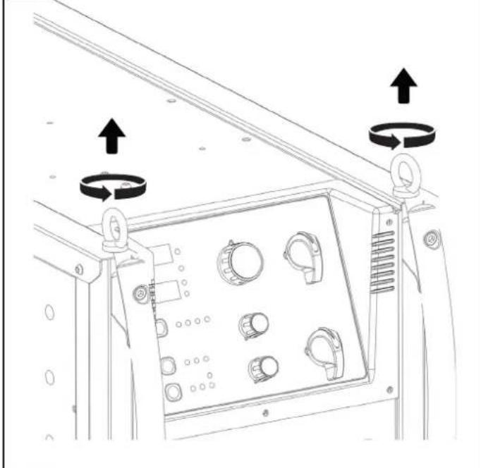
PROTECTION ECRAN MAGYS / MAGYS PROTECTIVE SCREEN / SCHUTZHAUBE FÜR MAGYS / PANTALLA DE PROTECCIÓN PARA MAGYS / ЗАЩИТНЫЙ ЭКРАН ДЛЯ MAGYS / SCHERMO PROTETTIVO MAGYS / TELA PROTETIVA MAGYS
1
natural_image
Technical line drawing of a mechanical control panel with circular arrows indicating rotational motion (no text or symbols)2

natural_image
Technical line drawing of a mechanical assembly with circular arrows indicating rotation or adjustment (no text or symbols present)3

natural_image
Technical line drawing of a mechanical frame assembly (no text or symbols)SCHÉMA ÉLECTRIQUE / CIRCUIT DIAGRAM / SCHALTPLAN / ESQUEMA ELÉCTRICO / ЭЛЕКТРИЧЕСКАЯ СХЕМА / SCEMA ELETTRICO / ELEKTRISCHE SCHEMA
MAGYS 400-4

text_image
L1 L2 L3 T A1 A2 XO NO T1 L1 T2 L2 T3 L3 5106 51060 17 19 21 23 18 red 22 white 20 black 24 white M1 51060 red 9 11 51055 51055 9 11 13 15 red white 10 red 14 white 12 black 16 white M1 5 7 51055 51055 8 6 red white 2 red 6 white 4 black 8 white M1 4 2 red white SW2C SW1C MESURE L+ MESURE U+ MESURE I- MESURE I- MESURE I+ MOTodevidoir 51110 400 GR 51461 IMOTEUR MOTELR GACHELI E2 51135 GACHETTEI 400 51461 POS 1 2 1-2 X 3-4 X 5-6 X 7-8 X 9-10 X 11-12 X 53055 SW1D 51060 POS 1 2 3 4 5 6 7 8 9 10 X X X X X X X X X X X X X X X X X X X X X X X X X X X X X X X X X X X X X X X X X X X X X X X X X X X X X X X X X X X X X X X X X X X X X X X X X X X X X X X X X X X X X X X X X X X X X X X X X X X X Y XX XX XX XX XX XX XX XX XX XX XX XX XX XX XX XX XX XX XX XX XX XX XX XX XX XX XX XX XX XX XX XX XX XX XX XX XX XX XX XX XX XX XX XX XX XX XX XX XX XX XX XX XX XX XX XX XX XX XX XX XX XX XX XX XX XX XX XX XX XX XX XX XX XX XX XX XX XX XX XX XX XX XX XX XX XX XX XX XX XX XX XX XX XX XX XX XX XX XXX XXX XXX XXX XXX XXX XXX XXX XXX XXX XXX XXX XXX XXX XXX XXX XXX XXX XXX XXX XXX XXX XXX XXX XXX XXX XXX XXX XXX XXX XXX XXX XXX XXX XXX XXX XXX XXX XXX XXX XXX XXX XXX XXX XXX XXX XXX XXX XXX XXX XXX XXX XXX XXX XXX XXX XXX XXX XXX XXX XXX XXX XXX XXX XXX XXX XXX XXX XXX XXX XXX XXX XXX XXX XXX XXX XXX XXX XXX XXX XXX XXX XXX XXX XXX XXX XXX XXX XXX XXX XXX XXX XXX XXX XXX XXX XXX XXX XXX XXXXXXXXXXXXXXXXXXXXXXXXXXXXXXXXXXXXXXXXXXXXXXXXXXXXXXXXXXXXXXXXXXXXXXXXXXXXXXXXXXXXXXXXXXXXXXXXXXXXXXXXXXXXXXXXXXXXXXXXXXXXXXXXXXXXXXXXXXXXXXXXXXXXXXXXXXXXXXXXXXXXXXXXXXXXXXXXXXXXXXXXXXXXXXXXXXXXXXXXXXXXXXXXXXXXXXXXXXXXXXXXXXXXXXXXXXXXXXXXXXXXXXXXXXXXXXXXXXXXXXXXXXXXXXXXXXXXXXXXXXXXXXXXXXXXXXXXXXXXXXXXXXXXXXXXXXXXXXXXXXXXXXXXXXXXXXXXXXXXXXXXXXXXXXXXXXXXXXXXXXXXXXXXXXXXXXXXXXXXXXXXXXXXXXXXXXXXXXXXXXXXXXXXXXXXXXXXXXXXXXXXXXXXXXXXXXXXXXXXXXXXXXXXXXXXXXXXXXXXXXXXXXXXXXXXXXXXXXXXXXXXXXXXXXXXXXXXXXXXXXXXXXXXXXXXXXXXXXXXXXXXXXXXXXXXXXXXXXXXXXXXXXXXXXXXXXXXXXXXXXXXXXXXXXXXXXXXXXXXXXXXXXXXXXXXXXXXXXXXXXXXXXXXXXXXXXXXXXXXXXXXXXXXXXXXXXXXXXXXXXXXXXXXXXXXXXXXXXXXXXXXXXXXXXXXXXXXXXXXXXXXXXXXXXXXXXXXXXXXXXXXXXXXXXXXXXXXXXXXXXXXXXXXXXXXXXXXXXXXXXXXXXXXXXXXXXXXXXXXXXXXXXXXXXXXXXXXXXXXXXXXXXXXXXXXXXXXXXXXXXXXXXXXXXXXXXXXXXXXXXXXXXXXXXXXXXXXXXXXXXXXXXXXXXXXXXXXXXXXXXXXXXXXXXXXXXXXXXXXXXXXXXXXXXXXXXXXXXXXXXXXXXXXXXXXXXXXXXXXXXXXXXXXXXXXXXXXXXXXXXXXXXXXXXXXXXXXXXXXXXXXXXXXXXXXXXXXXXXXXXXXXXXXXXXXXXXXXXXXXXXXXXXXXXXXXXXXXXXXXXXXXXXXXXXXXXXXXXXXXXXXXXXXXXXXXXXXXXXXXXXXXXXXXXXXXXXXXXXXXXXXXXXXXXXXXXXXXXXXXXXXXXXXXXXXXXXXXXXXXXXXXXXXXXXXXXXXXXXXXXXXXXXXXXXXXXXXXXXXXXXXXXXXXXXXXXXXXXXXXXXXXXXXXXXXXXXXXXXXXXXXXXXXXXXXXXXXXXXXXXXXXXXXXXXXXXXXXXXXXXXXXXXXXXXXXXXXXXXXXXXXXXXXXXXXXXXXXXXXXXXXXXXXXXXXXXXXXXXXXXXXXXXXXXXXXXXXXXXXXXXXXXXXXXXXXXXXXXXXXXXXXXXXXXXXXXXXXXXXXXXXXXXXXXXXXXXXXXXXXXXXXXXXXXXXXXXXXXXXXXXXXXXXXXXXXXXXXXXXXXXXXXXXXXXXXXXXXXXXXXXXXXXXXXXXXXXXXXXXXXXXXXXXXXXXXXXXXXXXXXXXXXXXXXXXXXXXXXXXXXXXXXXXXXXXXXXXXXXXXXXXXXXXXXXXXXXXXXXXXXXXXXXXXXXXXXXXXXXXXXXXXXXXXXXXXXXXXXXXXXXXXXXXXXXXXXXXXXXXXXXXXXXXXXXXXXXXXXXXXXXXXXXXXXXXXXXXXXXXXXXXXXXXXXXXXXXXXXXXXXXXXXXXXXXXXXXXXXXXXXXXXXXXXXXXXXXXXXXXXXXXXXXXXXXXXXXXXXXXXXXXXXXXXXXXXXXXXXXXXXXXXXXXXXXXXXXXXXXXXXXXXXXXXXXXXXXXXXXXXXXXXXXYxxxxxxxxxxxxxxxxxxxxxxxxxxxxxxxxxxxxxxxxxxxxxxxxxxxxxxxxxxxxxxxxxxxxxxxxxxxxxxxxxxxxxxxxxxxxxxxxxxxxxxxxxxxxxxxxxxxxxxxxxxxxxxxxxxxxxxxxxxxxxxxxxxxxxxxxxxxxxxxxxxxxxxxxxxxxxxxxxxxxxxxxxxxxxxxxxxxxxxxxxxxxxxxxxxxxxxxxxxxxxxxxxxxxxxxxxxxxxxxxxxxxxxxxxxxxxxxxxxxxxxxxxxxxxxxxxxxxxxxxxxxxxxxxxxxxxxxxxxxxxxxxxxxxxxxxxxxxxxxxxxxxxxxxxxxxxxxxxxxxxxxxxxxxxxxxxxxxxxxxxxxxxxxxxxxxxxxxxxxxxxxxxxxxxxxxxxxxxxxxxxxxxxxxyxyxyxyxyxyxyxyxyxyxyxyxyxyxyxyxyxyxyxyxyxyxyxyxyxyxyxyxyxyxyxyxyxyxyxyxyxyxyxyxyxyxyxyxyxyxyxyxyxyxyxyxyxyxyxyxyxyxyxyxyxyxyxyxyxyxyxyxyxyxyxyxyxyxyxyxyxyxyxyxyxyxyxyxyxyxyxyxyxyxyxyxyxyxyxyxyxyxyxyxypxypxypxypxypxypxypxypxypxypxypxypxypxypxypxypxypxypxypxypxypxypxypxypxypxypxypxypxypxypxypxypxypxypxypxypxypxypxypxypxypxypxypxypxypxypxypxypxypxypxvp:xxxxxxxxxxxxxxxxxxxxxxxxxxxxxxxxxxxxxxxxxxxxxxxxxxxxxxxxxxxxxxxxxxxxxxxxxxxxxxxxxxxxxxxxxxxxxxxxxxxxxxxxxxxxxxxxxxxxxxxxxxcc:cccccccccccccccccccccccccccccccccccccccccccccccccccccccccccccccccccccccccccccccccccccccccccccccccccccccccccccccccccccccccccccccccccccccccccccccccccccccccccccccccccccccccccccccccccccccccccccccccccccccccccccccccccccccccccccccccccccccccccccccccccccccccccccccccccccccccccccccccccccccccccccccccccccccccccccccccccccccccccccccccccccccccc:cc:cc:cc:cc:cc:cc:cc:cc:cc:cc:cc:cc:cc:cc:cc:cc:cc:cc:cc:cc:cc:cc:cc:cc:cc:cc:cc:cc:cc:cc:cc:cc:cc:cc:cc:cc:cc:cc:cc:cc:cc:cc:cc:cc:cc:cc:cc:cc:cc:cc:sseccc:seccc:seccc:seccc:seccc:seccc:seccc:seccc:seccc:seccc:seccc:seccc:seccc:seccc:seccc:seccc:seccc:seccc:seccc:seccc:seccc:seccc:seccc:seccc:seccc:seccc:seccc:seccc:seccc:seccc:seccc:seccc:seccc:seccc:soeeee: Soeeee: Soeeee: Soeeee: Soeeee: Soeeee: Soeeee: Soeeee: Soeeee: Soeeee: Soeeee: Soeeee: Soeeee: Soeeee: Soeeee: Soeeee: Soeeee: Soeeee: Soeeee: Soeeee: Soeeee: Soeeee: Soeeee: Soeeee: Soeeee: Soeeee: SMEUSE L+ MESURE U+ MESURE U+ MESURE L- MESURE L+ MESURE L+ MESURE L+ MESURE L+ MESURE L+ MESURE L+ MESURE L+ MESURE L+ MESURE L+ MESURE L+ MESURE L+ MESURE L+ MESURE L+ MESURE L+ MESURE L+ MESURE L+ MESURE L+ MESURE L+ MESURE L+ MESURE L+ MESURE L+ MESURE L+ MESURE L+ MESURE L+ MESURE L+ MESURE L- MESURE L+ MESURE L+ MESURE L+ MESURE L+ MESURE L+ MESURE L+ MESURE L+ MESURE L+ MESURE L+ MESURE L+ MESURE L+ MESURE L+ MESURE L+ MESURE L+ MESURE L+ MESURE L+ MESURE L+ MESURE L+ MESURE L+ MESURE L+ MESURE L+ MESURE L+ MESURE L+ MESUREL- MESURE L+ MESURE L+ MESURE L+ MESURE L+ MESURE L+ MESURE L+ MESURE L+ MESURE L+ MESURE L+ MESURE L+ MESURE L+ MESURE L+ MESURE L+ MESURE L+ MESURE L+ MESURE L+ MESURE L+ MESURE L+ MESURE L+ MESURE L+ MESURE L+ MESURE L+ MESURE L+ MESURE L+ MESUREL- MESUREL- MESUREL- MESUREL- MESUREL- MESUREL- MESUREL- MESUREL- MESUREL- MESUREL- MESUREL- MESUREL- MESUREL- MESUREL- MESUREL- MESUREL- MESUREL- MESUREL- MESUREL- MESUREL- MESUREL- MESUREL- MESUREL- MESUREL- MESUREL- MESUREL. MESUREL- MESUREL- MESUREL- MESUREL- MESUREL- MESUREL- MESUREL- MESUREL- MESUREL- MESUREL- MESUREL- MESUREL- MESUREL- MESUREL- MESUREL- MESUREL- MESUREL- MESUREL- MESUREL- MESUREL- MESUREL- MESUREL- MESUREL- MESUREL- MESUREL, FELF: SELF: SELF: SELF: SELF: SELF: SELF: SELF: SELF: SELF: SELF: SELF: SELF: SELF: SELF: SELF: SELF: SELF: SELF: SELF: SELF: SELF: SELF: SELF: SELF: SELF: SELF: SELF: SELF: SELF: SELF: SELF: SELF: SELF: SELF: SELF: SELF: SELF: SELF: SELF: SELF: SELF: SELF: SELF: SELF: SELF: SELF: SELF: SELF: SELF: SELF: Self: Self: Self: Self: Self: Self: Self: Self: Self: Self: Self: Self: Self: Self: Self: Self: Self: Self: Self: Self: Self: Self: Self: Self: Self: Self: Self: Self: Self: Self: Self: Self: Self: Self: Self: Self: Self: Self: Self: Self: Self: Self: Self: Self: Self: Self: Self: Self: Self: Self: self:
text_image
97161 53092 53101 53100 97165 SELF+ SELF- MESURE L+ MESURE L- T L1 L2 L3 97208 1 5 1 10 IH_1 IH_2 MESURE I+ MESURE I- A2 A1 F1512 +MOTEUR -MOTEUR GACHETTE2 GACHETTE3 SORTIE 1 SORTIE_ 9Vac 15Vac 8Vac 32462 98060MAGYS 400 GR

text_image
L1 L2 L3 T 21470 A1 A2 NO NO T1 L1 72 L2 13 L3 51106 17 19 21 23 18 red 22 white 20 black 24 white M1 9 11 12 10 white 10 red 14 white 12 black 16 white M1 9 11 13 15 8 5 red white 2 red 6 white 4 black 8 white M1 5 7 1 3 red white SW2C SW1C 51055 51060 96056 TH + TH 2 SW1D 51060 POS 1 2 1-2 X 3-4 X 5-6 X 7-8 X 9-10 X X 11-12 X X POS 1 2 3 4 5 6 7 8 9 10 1-2 X 3-4 X X X X X X X X X X X X X X X X X X X X X X X X X X X X X X X X X X X X X X X X X X X X X X X X X X X X X X X X X X X X X X X X X X X X X X X X X X X X X X X X X X X X X X X X X X X X X X X X X X X X Y 400 GR 51461 IMOTEUR M MOTEUR GACHETTE2 GACHETTE1 Motodévidoir 51110 400 SORTIE L+ SORTIE - MESURF L- MESURE L- SELF- SELF- MESURE U- X 96058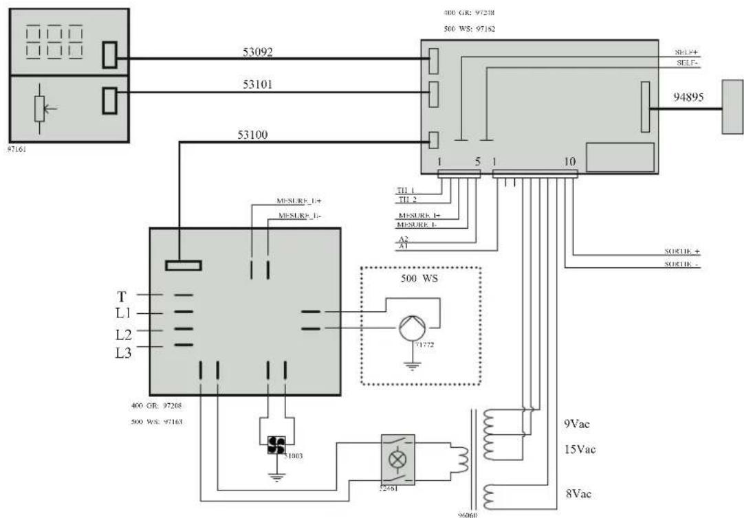
text_image
97161 53092 53101 53100 300 GR: 97248 500 WS: 97182 SELF+ SELF- 94895 T L1 L2 L3 TII 1 TII 2 MEASURE 1+ MEASURE 2 A2 A1 500 WS 400 GR: 97268 500 WS: 97163 31003 52491 96060 9Vac 15Vac 8VacMAGYS 500 GR

text_image
L1 L2 L3 T 21470 21420 A1 A2 NO NO L3 L2 L1 T1 51107 51107 T2 T3 17 19 21 23 18 red 22 white 20 black 24 white M1 black 51060 4 6 51060 51065 51065 51065 51065 51065 51065 51065 51065 51065 51065 51065 51065 51065 51065 51065 51065 51065 51177 SW2C SW1C TH 1 TH 96057 51355 COMPUTATOR 3pos. 51065 51065 SW1D 51060 POS 1 2 3 1-2 X 3-4 X 5-6 X X 7-8 X X 9-10 X X 11-12 X X 13-14 X X 15-16 X X 17-18 X X SWEURE U- SORTIE - SORTIE - MEASURE 1- MEASURE 1+ 96099 96099 SFLF- SFLF- MEASURE U- POS 1 2 3 4 5 6 7 8 9 10 1-2 X X X X X X X X X X X X X X X X X X X X X X X X X X X X X X X X X X X X X X X X X X X X X X X X X X X X X X X X X X X X X X X X X X X X X X X X X X X X X X X X X X X X X X X X X
text_image
97161 53092 53101 53100 T L1 L2 L3 97163 400 GR: 97268 500 WS: 97163 53100 MISURE_1+ MISURE_2- 500 WS 71772 52451 96068 94895 480 GR: 97248 500 WS: 97162 500 GR: 97162 115 10 TJ1 1 TJ2 MISURE_1+ MESURE_1- A2 A1 SORTIE_+ SORTIE_ 9Vac 15Vac 8VacMAGYS 400-4 / 400 GR / 500 GR / 500 WS
MAGYS 500 WS
| A1 A2 | |||||||||||||||||
| NO NO | |||||||||||||||||
| L1 | L3 | T3 | 17 19 | ||||||||||||||
| L2 | L2 | T2 | 21 23 | ||||||||||||||
| L3 | 21470 | L1 | T1 | ||||||||||||||
| T | 21470 | 51107 | 51060 | ||||||||||||||
| 51107 | 2 | ||||||||||||||||
| 51060 | 4 | ||||||||||||||||
| SW2D | 1 3 5 | 6 | |||||||||||||||
| POS 1 2 3 | 51065 | ||||||||||||||||
| 1-2 | X | ||||||||||||||||
| 3-4 | X | 9 | 11 | ||||||||||||||
| 5-6 | X | 13 | 15 | ||||||||||||||
| 7-8 | X | ||||||||||||||||
| 9-10 | X | 8 | |||||||||||||||
| 11-12 | X | 10 | |||||||||||||||
| 13-14 | X | 7 9 11 | 12 | ||||||||||||||
| 15-16 | X | 51065 | |||||||||||||||
| 17-18 | X | 2 | red | ||||||||||||||
| exclustment_3pos_51065 | 1 | 3 | |||||||||||||||
| 51065 | 5 | 7 | |||||||||||||||
| SW1D | 8 | white M1 | |||||||||||||||
| 51060 | |||||||||||||||||
| POS 1 2 3 4 5 6 7 8 9 10 | 14 | ||||||||||||||||
| 1-2 | X | 131517 | 16 | ||||||||||||||
| 3-4 | XXX | 18 | |||||||||||||||
| 5-6 | XXX | ||||||||||||||||
| 7-8 | XXX | SW2C | SW1C | ||||||||||||||
| 9-10 | X | X | 51065 | 51060 | |||||||||||||
| 11-12 | XXX | 51355 | |||||||||||||||
| 13-14 | XXX | ||||||||||||||||
| 15-16 | X | X | |||||||||||||||
| 17-18 | X | X | X | ||||||||||||||
| 19-20 | XXX | ||||||||||||||||
| 21-22 | XXX | X | |||||||||||||||
| 23-24 | |||||||||||||||||
| 400 GR: 97248 | |||||||||||||||||
| 500 WS: 97362 | 500 GR: 97362 | ||||||||||||||||
| 53092 | |||||||||||||||||
| 53101 | |||||||||||||||||
| 53100 | |||||||||||||||||
| 97161 | 1 15 | 10 | |||||||||||||||
| MISURP_L+ | TII 1 | ||||||||||||||||
| MISURP_L- | TII 2 | ||||||||||||||||
| MISURE_I+ | |||||||||||||||||
| MESURE I- | |||||||||||||||||
| A2 | |||||||||||||||||
| A1 | |||||||||||||||||
| 500 | WS | ||||||||||||||||
| T | |||||||||||||||||
| L1 | |||||||||||||||||
| L2 | 71772 | ||||||||||||||||
| L3 | |||||||||||||||||
| 400 GR: 97208 | |||||||||||||||||
| 500 WS: 97163 | 9Vac | ||||||||||||||||
| 51063 | 15Vac | ||||||||||||||||
| 52461 | 8Vac | ||||||||||||||||
SPÉCIFICATIONS TECHNIQUES / TECHNICAL SPECIFICATIONS / TECHNISCHE DATEN / TEXНИЧЕСКИЕ СПЕЦИФИКАЦИИ / ESPECIFICACIONES TÉCNICAS / TEXНИЧЕСКИЕ СПЕЦИФИКАЦИИ / TECHNISCHE GEGEVENS / SPECIFICHE TECNICHE
| MAGYS | 400-4 400 GR 500 GR 500 WS | |||
| 032170 0321 | 87 032194 03 | 2200 | ||
| Référence | ||||
| Primaire / Primary / Primär / Первичка / Primaire / Primario | ||||
| Tension d'alimentation / Power supply voltage / Stromversorgung / Напряжение питания / Voedingsspanning / Tensione di alimentazione | 400 V +/- 15% | |||
| Fréquence secteur / Mains frequency / Netzfrequenz / Частота сети / Frequentie sector / Frequenza settore | 50 / 60 Hz | |||
| Fusible disjoncteur / Fuse / Sicherung / Плавкий предохранитель прерывателя / Zekering hoofdschakelaar / Fusibile disgiuntore | 32 A 32 A | |||
| Secondaire / Secondary / Sekundär / Вторичка / Secondair / Secondario | ||||
| Tension à vide / No load voltage / Leerlaufspannung / Напряжение холостого хода / Nullastspanning / Tensione a vuoto | 43 V 51 V | |||
| Courant de sortie nominal ( I_2 ) / Normal current output ( I_2 ) / nominaler Ausgangsstrom ( I_2 ) / Номинальный выходной ток (I2) / Nominale uitgangsstroom (I2) / Corrente di uscita nominale (I2) | 40+350 A 45 | +450 A | ||
| Tension de sortie conventionnelle ( U_1 ) / Conventional voltage output ( U_1 ) / entsprechende Arbeitsspannung ( U_1 ) / Условное выходные напряжения (U2) / Conventionele uitgangsspanning (U2) / Tensione di uscita convenzionale (U2) | 16+31.5 V 16.25 | +36.5 V | ||
| Facteur de marche à 40°C (10 min)* | Einschaltdauer @ 40°C (10 min)* | Inschakelduur bij 40°C (10 min)* | 50 % | 350 A 450 A |
| Norme IEC60974-1. | IEC60974-1 -Norm. | Norm IEC60974-1. | 60 % | 320 A 410 A |
| Duty cycle at 40°C (10 min)* | ПВ% при 40°C (10 мин)* | Ciclo di lavoro a 40°C (10 min)* | 100 % | 260 A 320 A |
| Standard IEC60974-1. | Норма IEC60974-1. | Norma IEC60974-1. | ||
| Vitesse de moteur / Motor speed / Velocidad de motor / Скорость двигателя / Snelheid motor / Velocità del motore | 1 > 24 m/min | - | - | |
| Fils supportés / Supported wires / Alambres/hilos soportados / Подходящие виды проволоки / Ondersteunde draden / Fili supportati | Fe 0.6 > 1.2 mm | - | - | |
| UHSS 0.8 > 1.2 mm | - | - | ||
| Al 1.0 > 1.2 mm | - | - | ||
| Cored - | - | |||
| Bobines supportées / Supported wire reels / Bobinas soportadas / Подходящие бобины / Ondersteunde spoelen / Bobine supportate | 200-300 mm | - | - | |
| Pression maximale de gaz (Pmax) | 0.5 MPa (5 bars) | - | - | |
| Type de galet / Drive roller type / Drahtführungsrolle-Typ / Tipo de rodillo / Тип ролика / Type draadaanvoerrol / Tipo di ruilo | C | - | - | |
| Température de fonctionnement / Functioning temperature / Betriebstemperatur / Рабочая температура / Gebruikstemperatuur / Temperatura di funzionamento | -10°C → +40°C | |||
| Température de stockage / Storage temperature / Lagerungstemperatur / Температура хранения / Bewaartemperatuur / Temperatura di stoccaggio | -20°C → +55°C | |||
| Degré de protection / Protection level / Schutzgrad / Степень защиты / Beschermingsklasse / Grado di protezione | IP23 | |||
| Dimensions (Lxlxh) / Dimensions (Lxlxh) / Abmessung (LxBxH) / Размеры (ДхШхВ) / Afmetingen (Lxlxh) / Dimensioni (Lxlxh) | 50 x 105 x 98 cm | |||
| Poids / Weight / Gewicht / Bec / Gewicht / Peso | 130 kg | 160 kg | ||
*The duty cycles are measured according to standard IEC60974-1 à 40°C and on a 10 min cycle.
While under intensive use (> to duty cycle) the thermal protection can switch on, in that case, the arc stops and the indicator switches on.
Keep the machine's power supply on to enable cooling until the thermal protection switches off.
The machine has a specification with a "constant current output" in MIG/MAG.
In some countries, U0 is called TCO.