
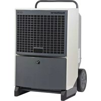
CDF 10 - Dehumidifier Dantherm - Free user manual and instructions
Find the device manual for free CDF 10 Dantherm in PDF.
| Product type | Refrigeration condensation dehumidifier |
| Brand | Dantherm |
| Model | CDF 10 |
| Dimensions (H × W × D) | 600 × 535 × 240 mm |
| Weight | 28 kg |
| Power supply | 230 V / 50 Hz |
| Max. power consumption | 0.30 kW |
| Max. current consumption | 2.1 A |
| Max. air flow | 220 m³/h |
| Refrigerant | R134a (charge 0.190 kg, GWP 1430) |
| Humidity range | 40–100 % RH |
| Ambient temperature range | 3–30 °C |
| Noise level (at 1 m) | 46 dB(A) |
| Control | Adjustable built-in hygrostat (≈60 % RH default) |
| Defrost function | Automatic if evaporator <5 °C, 44 min cycle |
| Compressor protection | 45-second restart delay |
| Thermal safety | Auto shut-off if condenser >55 °C or ambient temperature <3 °C/>30 °C |
| Full tank shutdown | Automatic (with optional tank) – flashing red LED |
| Monthly maintenance | Cleaning the intake filter |
| Annual maintenance | Internal cleaning (condenser, evaporator) |
| Lubrication | Lifetime lubrication – no maintenance required |
| Accessories | Optional water tank, possible lift pump |
| Spare parts | Available: see list in manual (pages 114+) |
| Warranty / Compliance | Compliant with EU directives (89/392, 73/23, 89/336) |
Frequently Asked Questions - CDF 10 Dantherm
User questions about CDF 10 Dantherm
0 question about this device. Answer the ones you know or ask your own.
Ask a new question about this device
Download the instructions for your Dehumidifier in PDF format for free! Find your manual CDF 10 - Dantherm and take your electronic device back in hand. On this page are published all the documents necessary for the use of your device. CDF 10 by Dantherm.
USER MANUAL CDF 10 Dantherm
General information....5
General information....15
Product- and functional description....16
Mounting and installation....19
Service guide....21
Fault finding guide 22
Technical data 23
Einführung (de) 24
Allgemeines 25
natural_image
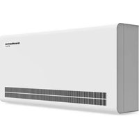
Exterior view of a gray server or rack unit with ventilation grilles and directional arrows indicating flow (no text or symbols)natural_image
3D rendering of a mechanical housing or enclosure with internal compartments and a small component (no text or symbols visible)It is the responsibility of the operator to read and understand this service manual and other information provided, and to use the correct operating procedures.
Read the entire manual before the initial start-up of the dehumidifier. It is important to know the correct operating procedures for the unit and all safety precautions to prevent the possibility of property damage and/or personal injury.
Table of contents
This service manual covers the following main topics:
| Topic | See page |
| General information | 15 |
| Product- and functional description | 16 |
| Mounting and installation | 19 |
| Service guide | 21 |
| Fault finding guide | 22 |
| Technical data | 23 |
| Appendix | 108 |
| Eldiagram/Wiring diagram/Schaltplan/Schéma électrique/Cxema coединений/Schema elettrico/Esquema eléctrico/Diagrama elétrico | 111 |
| Ordforklaring/Legend/Legende/Légende/Обозначение/Legenda/Leyenda/ Legenda | 112 |
| Reservedele/Spare parts/Ersatzteile/Pièces de rechange/Запасные части/Parti di ricambio/Piezas de repuesto/Peças sobresselentes | 114 |
General information
| Introduction | This section gives the general information about this service manual and about the unit |
| Manual, part num-ber | Part number of this service manual is 975677. |
| Target group | The target group for this service manual is the technicians who install, maintain, and exchange parts on the unit. |
| Copyright | Copying of this service manual, or part of it, is forbidden without prior written permission from Dantherm A/S. |
| Reservations | Dantherm A/S reserves the right to make changes and improvements to the product and the service manual at any time without prior notice or obligation. |
| EC-Declaration of Conformity | Dantherm A/S, Marienlystvej 65, DK-7800 Skive hereby declare that the unit mentioned below:Dehumidifier, model CDF 10, product no. 351612:covered by this declaration, is in conformity with the following directives:89/392/EEC Directive on the Safety of Machines 73/23/EECLow Voltage Directive89/336/EEC EMC Directive- and is manufactured in conformity with the following standards:EN 60 335-2-40 Standard for electric dehumidifiersEN 292 Machine safetyEN 50081-1 EMC Generic standard for emissionEN 50082-1 EMC Generic standard for immunitySkive, 04.02.2002 |
| Recycling | The unit is designed to last for many years. When the time comes for the unit to be re-cycled, the unit should be recycled according to national rules and procedures to pro-tect the environment.The dehumidifier contains R134a refrigerant and compressor oil. The compressor must in connection with disposal be returned to authorities. |
Product- and functional description
Introduction
This section will give you a description of the CDF 10 and its functionality.
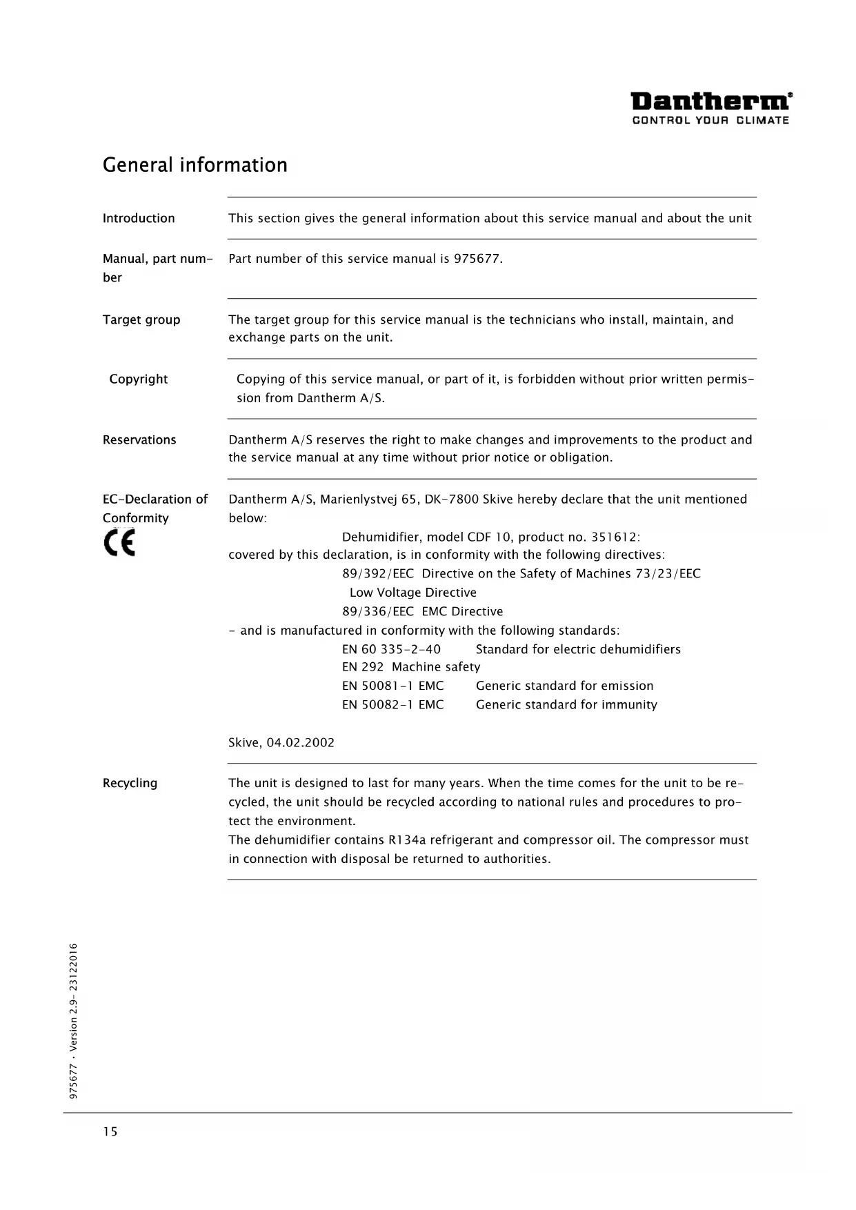
Description of function
CDF 10 is working in accordance with the condensation principle. The humid air is drawn into the unit by a fan. When passing through the evaporator the air is cooled down to below dew point and water vapor is condensed into water, which is drained away. The now dry air is then passed over the condenser coil where the air is heated. As a result of the released evaporator heat and the working energy of the compressor being turned into heat energy, more heat is returned to the air than was previously extracted. This extra heat corresponds to an approximate increase in temperature of 5 °C. The repeated circulation of air through the unit reduces the relative humidity, giving very rapid but gentle drying.
Air flow
The following illustrates the air flow:
natural_image
3D rendering of a gray server or rack unit with ventilation grilles and mounting holes, shown with directional arrows (no text or symbols)Built-in hygrostat
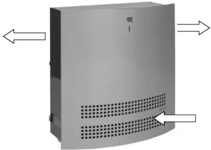
The dehumidifier is controlled by a built-in hygrostat that is set to approx. 60 % RH. When the hy-grostat registers a relative humidity of more than 60 %RH, the compressor and the fan automatically switch on and the dehu-midifier starts to dehumidify. The front panel has to be removed before adjusting the hygrostat. The hygrostat is located under the control box and can be adjusted by turning the set screw.
pie
| Segment | Value (%) | |---|---| | Segment 1 | 60 | | Segment 2 | 20 | | Segment 3 | 80 |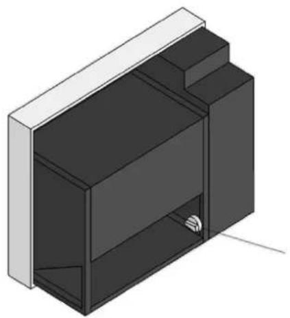
natural_image
3D rendering of a mechanical housing or enclosure with internal compartments and a small component (no text or symbols visible)Continued overleaf
Product- and functional description, continued
| Built-in hygrostat, continued | OBS! If the air humidity is below 60 %RH, the unit will not start when the power is connected. If you want to set the hygrostat at a lower relative humidity than 60% the set screw has to be turned clockwise.We recommend installing an external hygrostat if you want to change/adjust the setting of relative humidity very often. |
| LED indication/switch | The LED on the front of the unit is green when the compressor is operating, and the unit dehumidifies.The dehumidifier is switched on and off by the switch on the side.Note! Any stop of the unit - either caused by failing power connection, by the switch on the side of the unit, by the hygrostat, or by the water tank's water stop function - will make the electronic control put off re-start for 45 seconds in order to protect the compressor from being switched on and off repeatedly. |
| Compressor control | At compressor start, the solenoid valve opens up for at least 10 sec. in order to relieve the pressure on the compressor starting circuit.Any stop of the unit - either caused by failing power connection, by the switch on the side of the unit, by the hygrostat, or by the water tank's water stop function - will make the electronic control put off re-start for 45 seconds in order to protect the compressor from being switched on and off repeatedly. |
| Defrosting | If the temperature falls to below 20 °C the evaporator may start to ice up after a short time.The defrosting function is activated when the evaporator sensor registers a temperature lower than 5 °C, after which the control will let the unit operate in dehumidification mode for another 44 minutes. Then the fan is stopped, hot refrigerant is bypassed the condenser and is finally led through the evaporator where it melts the ice. When the evaporator sensor registers that the temperature is above 5 °C, the fan starts again. |
| Safety circuit | If the temperature on the condenser coil increases to a temperature of more than 55 °C (for example in case of fan failure), the compressor is stopped automatically to avoid any damage. After 44 minutes the compressor starts again automatically.At room temperatures lower than 3 °C and higher than 30 °C the unit is automatically switched off to protect the cooling plant against icing up or superheating. When the temperature is higher than 3 °C or lower than 30 °C the dehumidifier will automatically start again. The temperature is registered by a sensor on the PCB. |
| Water tank | If it is not possible to mount a fixed or a flexible drain outlet connection, the CDF 10 can be used with a water tank.If the CDF 10 is used with a water tank, it switches off automatically when the water tank is full. A red LED on the front panel flashes when the water tank needs to be emptied.The water tank is an extra accessory for the CDF 10 and is available on demand.The water tank consists of the following parts:Water tank cabinet with magnetic switch for water stop and cable for connection to PCBWater tank4 machine screws |
Mounting and installation
Suspension
The wall suspension bar supplied with the unit is fixed to the wall and the dehumidifier is hung up on it. It is important to mount the unit in a horizontal position to secure correct outflow of the condensate water.
The dehumidifier must be placed in a way that allows unimpeded air intake through the front and outlet through the grill on the sides. Be sure always to leave at least 100 mm free space around the unit for optimum operation.
It is important that the dehumidifier is not installed near a source of heat as for example a radiator, and doors and windows must be kept closed when the dehumidifier is in function.
Installation of the water tank
- Place the CDF 10 on the wall by means of the wall suspension bar.
- Then dismantle the front panel of the CDF 10.
- Fix the water container cabinet by 4 machine screws under the bottom of the CDF 10.
- Take the supply cable through the diaphragm bush at the bottom of the water tank cabinet.
- The control of the CDF 10 is placed in a box behind the front panel. To get access to the control, unscrew the 4 screws on the sides of the box and remove the box lid.
- Take the cable from the magnetic switch through the diaphragm bush at the bottom of the CDF 10 and connect it to the terminal strip on the PCB - terminal points 13/14 (WATER SW).
- Remount the control box lid and the front panel.
- Place the water tank in the water tank cabinet. The float must be turned towards the magnetic switch.
Drawing
The water tank is mounted beneath the CDF 10 as shown on the drawing:
Continued overleaf
Mounting and installation, continued
| Note | On the rear of the unit a cable binder protects the compressor during transport. This cable binder must be removed before suspension and power connection |
| Condensate outlet | The condensate outlet is located at the bottom of the dehumidifier. The unit has a drain spigot intended for connection of a 1⁄2” flexible or fixed water connection. If water drain through the wall is chosen, a suitable hole is made in the wall and the condensate hose is led out through this hole, before suspending the dehumidifier on the wall suspension bar.As an alternative a condensate pump can be fitted at the water outlet to pump the water to a drain. |
| Placing of the condensate outlet | The placing of the condensate outlet is shown on the drawing: |
| Connection of power supply | The unit is delivered complete with cable and plug for connection to 230V/50Hz.Power is connected to the unit in accordance with the nameplate. Please refer to the wiring diagram on page 111.Note: All electrical connections must be made in accordance with local power supply. |
Service guide
| Access to the control | Remove the front panel by unscrewing the two screws on the top of the dehumidifier. Lift the front panel vertically upwards and then pull it horizontally away from the unit. The control of the unit is located in a box behind the front panel. To get access to the control unscrew the 4 screws on the sides. | |
| Maintenance | The dehumidifier requires very little attention for trouble free running. All the necessary safety and control functions have been built in. The fan motor and the compressor have permanent lubrication and require no particular maintenance. | |
| Cleaning of the dehumidifier | Once a month | Once a year |
| Once a month the air inlet filter should be checked and cleaned if necessary. The front cover panel is removed and the filter taken out. Clean the filter in tepid soapy water or if not badly soiled by vacuum cleaning | Once a year the front cover panel should be removed in order to check the inside of the dehumidifier. If the dehumidifier is dirty it should be cleaned by vacuum cleaning. The condenser in particular should be thoroughly vacuumed. If the tube evaporator is badly soiled, it may be washed in tepid soapy water | |
Fault finding guide
Note!
If the dehumidifier is not functioning correctly, shut it down immediately
Fault finding
Use this table to localize and solve a possible problem or fault:
| Fault | Solution |
| The dehumidifier does not start when power is connected | Check external fusesCheck that the power supply to the units is correctCheck that the switch on the side is ONCheck the built-in hygrostat by setting it on a lower relative humidity. This is done by turning the hygrostat knob clockwise. If the unit does not start, check the built-in hygrostat for faults |
| The unit was switched off automatically | If it starts after 44 minutes, but switches off again shortly afterwards, check the following:Check that the fan is running when the unit starts after 44 minutesCheck whether the condenser coil is dirtyCheck whether the filter is dirtyCheck whether the room temperature is above 30 °C. If the unit has not been switched off automatically at a room temperature above 30 °C, it should be switched off.Check that the air inlet on the front and the air outlet through the grill on the sides are not blocked. |
| The evaporator coil has iced up and the unit does not separate water | Check whether the room temperature is below 3 °C. If so, and the unit has not automatically been switched off, it should be switched off.Check that the air inlet on the front and the air outlet through the grill on the sides are not blocked |
| The LED on the front panel flashes in red and the water tank is empty | Check that the float is lying loose in the water tank and that it can move freely up and down. Check that the float is not damaged |
| The water tank is full and yet the dehumidifier is not switched off | Check that the water tank is placed in the water tank cabinet and that the float is turned towards the magnetic switchCheck that the float is lying loose in the water tank and that it can move freely up and down. Check that the float is not damaged |
More help
If you cannot find the reason for the fault, switch off the unit immediately in order to prevent further damage. Contact a service technician or a Dantherm representative.
Technical data
General data
The table shows the dehumidifier's general technical data:
| CDF 10 | ||
| Working area - humidity | %RF | 40-100 |
| Working area - temperature | °C | 3-30 |
| Power supply | V/Hz | 230/50 |
| Max. ampere consumption | A | 2,1 |
| Max. power consumption | kW | 0,30 |
| Air volume at max. external pressure | m^3/h | 220 |
| Refrigerant | - | R134a |
| Quantity of refrigerant | kg | 0,190 |
| GWP (Global Warming Potential) | - | 1430 |
| Sound level (1 m away from unit) | dB(A) | 46 |
| Weight | kg | 28 |
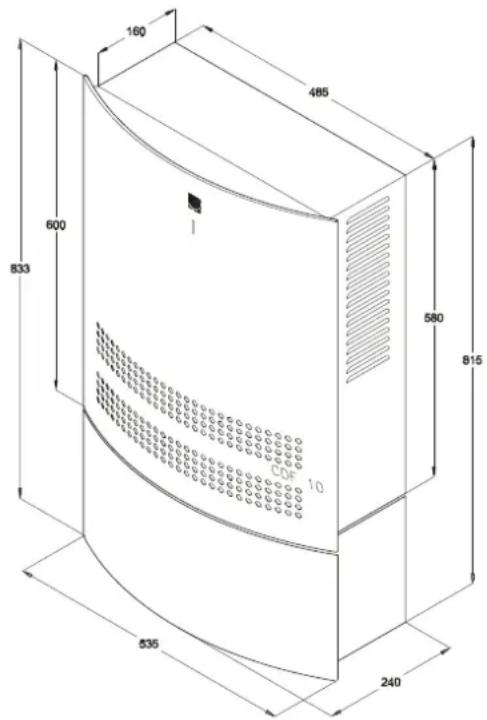
| Dimensions - H x L x W | mm | 600×535×240 |
Dimensions
The drawing shows the dimensions of the unit:

Einführung (de)
Übersicht
Warnhinweis
natural_image
3D rendering of a gray server or rack unit with ventilation grilles and mounting holes, shown with directional arrows (no text or symbols)pie
| Segment | Value | |---|---| | %RH | 60 | | Other | 80 | | Total | 20 |
natural_image
3D rendering of a mechanical housing or enclosure with internal compartments and a small component (no text or symbols visible)natural_image
3D rendering of a gray server or rack unit with ventilation grilles and mounting holes (no text or symbols visible)Dantherm
CONTROL YOUR CLIMATE
Hygrostat incorporé
natural_image
3D rendering of a mechanical housing or enclosure with internal compartments and a small component (no text or symbols visible)natural_image
Exterior view of a gray industrial device with ventilation grilles and directional arrows indicating airflow or movement (no text or symbols)natural_image
3D rendering of a mechanical housing or enclosure with internal compartments and a small component (no text or symbols visible)natural_image
Exterior view of a gray industrial enclosure with ventilation grilles and directional arrows indicating airflow or movement (no text or symbols)Umidostato interno
natural_image
3D mechanical component diagram with a magnified circular section showing percentage distribution (60%, 80%, 20%) and a small inset view of the component (no text or symbols on the main diagram)natural_image
3D rendering of a gray server or rack unit with ventilation grilles and mounting holes (no text or symbols visible)Dantherm
CONTROL YOUR CLIMATE
The front panel has to be removed before adjusting the hygrostat. The hygrostat is located under the control box and can be adjusted by turning the set screw.

pie
| Segment | Value (%) | |---|---| | Segment 1 | 60 | | Segment 2 | 80 | | Segment 3 | 20 |
natural_image
3D rendering of a mechanical housing or enclosure with internal compartments and a small sensor icon (no text or symbols)natural_image
Exterior view of a gray server rack unit with ventilation grilles and mounting holes (no text or symbols visible)Higróstato incorporado
The front panel has to be removed before adjusting the hygrostat. The hygrostat is located under the control box and can be adjusted by turning the set screw.

natural_image
Isometric illustration of a modular device with a central display unit and a small sensor or connector (no text or symbols)
natural_image
3D rendering of a gray server or rack unit with ventilation grilles and mounting holes, shown with directional arrows (no text or symbols)natural_image
3D technical illustration of a mechanical housing with an inset pie chart showing percentage distribution (60%, 80%, 20%) — no text or symbols present.natural_image
3D rendering of a gray server or rack unit with ventilation grilles and mounting holes, shown with directional arrows (no text or symbols)Dantherm
CONTROL YOUR CLIMATE
Inbyggd hygrostat
pie
| Segment | Value | |---|---| | Segment 1 | 60 | | Segment 2 | 80 | | Segment 3 | 20 | %RH label indicates the percentage value for Segment 1 at 60%. The chart is divided into three equal segments (each 20%, one 80%, one 60%) with directional arrows indicating direction. No numerical values or units are provided for the segments.
natural_image
3D rendering of a modular device with internal compartments and a small metallic component (no text or symbols visible)Fortsættes/continued overleaf/fortsetzt/Suite à la page suivante/Продолжение на след.стр./ continua alla pagina seguente/Continúa en el dorso./continuação no verso/ciag dalszy na odwrocie/forts. på nästa sida
Reservedele/Spare parts/Ersatzteile/Pièces de rechange/Запасные части/Parti di ricambio/Piezas de repuesto/Peças sobresselentes/Części zamienne/Reservdelar/Reservdelar

| Pos. | «Firma»nr./no. | DABeskrivelse | ENDesignation |
| 1 | 084767-046 | Vægbeslag | Wall suspension bar |
| 2 | 293647-046 | Kabinet kpl | Housing, cpl. |
| 3 | 601933 | Kompressor | Compressor |
| 3a | 510051 | Startrelæ | Starting relay |
| 3b | 510052 | Beskyttelse for relæ | Overload protector for relay |
| 4 | 084766 | - | - |
| 5 | 084753 | - | - |
| 6 | 532480 | Ventilatormotor | Fan motor |
| 7 | 532520 | Ventilatorvinge | Fan blade |
| 8 | 084764 | - | - |
| 9 | 084765 | - | - |
| 10 | 517581 | Printkort | Printed circuit board |
| 11 | 517603 | Diodeprint | Diode print |
| 12 | 605440 | Spole for magnetventil | Coil for solenoid valve |
| 13 | 605470 | Magnetventil | Solenoid valve |
| 14 | 517802 | Føler, metalnæse, 1150 mm | Sensor, metal nose, 1150 mm |
| 15 | 517804 | Føler, 1250 mm | Sensor, 1250 mm |
| 16 | 084750 | - | - |
| 17 | 515081 | Vippeafbryder | Toggle switch |
| 18 | 084751 | - | - |
| 19 | 600990 | Kondensatorflade | Condensor |
| 20 | 084752 | - | - |
| 21 | 516350 | Hygrostat | Hygrostat |
| 22 | 293646 | Holder for hygrostat | Retainer for hygrostat |
| 22a | 529404 | Skala for hygrostat | Scale for hygrostat |
| 23 | 541774 | Drejeknap | Adjusting knob |
| 24 | 607410 | Tørrefilter | Liquid line drier |
| 25 | 066694 | Kapillarrør | Capillary tube |
| 26 | 198332 | Fordamper | Evaporator |
| 27 | 293645 | Drypbakke, kpl. | Condensate tray, complete |
| 28 | 544150 | Afløbsstuds | Drain spigot |
Fortsættes/continued overleaf/fortsetzt/Suite à la page suivante/Продолжение на след.стр./continua alla pagina seguente/Continúa en el dorso./continuação no verso/ciąg dalszy na odwrocie
Reservedele/Spare parts/Ersatzteile/Pièces de rechange/Запасные части/Parti di ricambio/Piezas de repuesto/Peças sobresselentes/Części zamienne/Reservdelar/Reservdelar

| Pos. | «Firma»nr./no. | DABeskrivelse | ENDesignation |
| 29 | 524890 | Tilslutningskabel | Connection cable |
| 30 | 540131 | Afstandsstykke | Spacing piece |
| 31 | 293644 | Front, kpl | Front panel, complete |
| 31a | 528117 | Skilt - Dantherm logo | Label - Dantherm logo |
| 31b | 528627 | Skilt | Label |
| 31c | 084771 | Filter | Filter |
| 32 | 527500 | Kontramøtrik | Counter nut |
| 33 | 526900 | Kabelforskruning | Screwed cable entry |
| 34 | 084772 | Isolering | Insulation |
| Pos. | «Firma»Nr./no. | DEBeschreibung | FRDescription |
| 1 | 084767-046 | Wandkonsole | Barre d'ancrage |
| 2 | 293647-046 | Gehäuse, kpl. | Carrosserie cpl. |
| 3 | 601933 | Kompressor | Compresseur |
| 3a | 510051 | Startrelais | Relais de démarrage |
| 3b | 510052 | Schutz für Relais | Protection du relais |
| 4 | 084766 | - | - |
| 5 | 084753 | - | - |
| 6 | 532480 | Ventilatormotor | Moteur de ventilateur |
| 7 | 532520 | Ventilatorflügel | Ailette du ventilateur |
| 8 | 084764 | - | - |
| 9 | 084765 | - | - |
| 10 | 517581 | Printplatte | Platine électronique |
| 11 | 517603 | Diodenprint | Platine de diode |
| 12 | 605440 | Spule für Magnetventil | Bobine de la vanne magnétique |
| 13 | 605470 | Magnetventil | Vanne magnétique |
| 14 | 517802 | Fühler, Metallnase, 1150 mm | Sonde, nez métallique, 1150 mm |
| 15 | 517804 | Fühler, 1250 mm | Sonde, 1250 mm |
| 16 | 084750 | - | - |
Fortsættes/continued overleaf/fortsetzt/Suite à la page suivante/Продолжение на след.стр./continua alla pagina seguente/Continúa en el dorso./continuação no verso/ciąg dalszy na odwrocie
Reservedele/Spare parts/Ersatzteile/Pièces de rechange/Запасные части/Parti di ricambio/Piezas de repuesto/Peças sobresselentes/Części zamienne/Reservdelar/Reservdelar

| Pos. | «Firma»Nr./no. | DEBeschreibung | FRDescription |
| 17 | 515081 | Kippschalter | Interrupteur basculant |
| 18 | 084751 | - | - |
| 19 | 600990 | Kondensator | Condenseur |
| 20 | 084752 | - | - |
| 21 | 516350 | Hygrostat | Hygrostat |
| 22 | 293646 | Halter für Hygrostat | Support de l'hygrostat |
| 22a | 529404 | Skala für Hygrostat | Cadran de l'hygrostat |
| 23 | 541774 | Drehknopf | Bouton rotatif |
| 24 | 607410 | Trockenfilter | Filtre anti-humidité |
| 25 | 066694 | Kapillarrohr | Tubes capillaires |
| 26 | 198332 | Verdampfer | Evaporateur |
| 27 | 293645 | Kondensatschale, kpl. | Bac à eau, cpl. |
| 28 | 544150 | Ablaufstutzen | Orifice d'écoulement |
| 29 | 524890 | Anschlusskabel | Câble de raccordement |
| 30 | 540131 | Distanzrohr | Pièce d'écartement |
| 31 | 293644 | Deckplatte vorne, kpl. | Tôle frontale, cpl. |
| 31a | 528117 | Aufkleber - Dantherm Logo | Etiquette - Dantherm logo |
| 31b | 528627 | Aufkleber | Etiquette |
| 31c | 084771 | Filter | Filtre |
| 32 | 527500 | Gegenmutter | Contre-écrou |
| 33 | 526900 | Kabelverschraubung | Raccord à vis pour le cable |
| 34 | 084772 | Isolierung | Isolant |
Fortsættes/continued overleaf/fortsetzt/Suite à la page suivante/Продолжение на след.стр./continua alla pagina seguente/Continúa en el dorso./continuação no verso/ciąg dalszy na odwrocie /forts. på nästa sida
Reservedele/Spare parts/Ersatzteile/Pièces de rechange/Запасные части/Parti di ricambio/Piezas de repuesto/Peças sobresselentes/Części zamienne/Reservdelar/Reservdelar
| Pos. | «Firma»nr./no. | DABeskrivelse | ENDesignation |
| 1 | 084775-046 | Kabinet sider | Cabinet |
| 2 | 084793 | Beslag for magnetkontakt | Retainer for magnetic switch |
| 3 | 084797 | Magnetkontakt | Magnetic switch |
| 4 | 084794 | Stopskinne for vandbeholder | Stop rail for water container |
| 5 | 084792 | Holder for vandbeholder | Retainer for water container |
| 6 | 084776-046 | Kabinet bund | Cabinet bottom |
| 7 | 525440 | Kanthængsel | Edge hinge |
| 8 | 524190 | Membrantylle | Oil line grommet |
| 9 | 175537 | Svømmer | Float |
| 10 | 565745 | Vandbeholder, lille | Water container, small |
| 11 | 540652 | Snaplås | Snap lock |
| 12 | 172661 | Front vandbeholder (Hvid/sølv-venligst angiv) | Front, water container(White/Silver-please specify) |
| 13 | 084796 | Fjeder for vandbeholder | Spring for water container |


- Table of contents
- Product- and functional description
- Introduction
- Description of function
- Air flow
- Built-in hygrostat
- Mounting and installation
- Suspension
- Installation of the water tank
- Drawing
- Fault finding guide
- Technical data
- General data
- Dimensions
- Einführung (de)
- Übersicht
- Warnhinweis
- Dantherm
- CONTROL YOUR CLIMATE
- Hygrostat incorporé
- Umidostato interno
- Higróstato incorporado
- Inbyggd hygrostat
- Reservedele/Spare parts/Ersatzteile/Pièces de rechange/Запасные части/Parti di ricambio/Piezas de repuesto/Peças sobresselentes/Części zamienne/Reservdelar/Reservdelar
Brand : Dantherm
Model : CDF 10
Category : Dehumidifier