FXIG12 - Generator Fuxtec - Free user manual and instructions
Find the device manual for free FXIG12 Fuxtec in PDF.

| Product type | Generator |
| Brand | Fuxtec |
| Model | FXIG12 |
| Fuel | Unleaded petrol |
| Engine type | 4-stroke, single cylinder |
| Rated power | Approx. 2 kVA (230 V) |
| AC output voltage | 230 V |
| DC output | 12 V (battery charge) |
| Fuel tank capacity | Approx. 4 L |
| Engine oil capacity | Approx. 0.4 L |
| Fuel saving device | Automatic idle speed reduction |
| Oil level alarm system | Automatic engine shutdown if low level |
| Indicators | Voltage (V), frequency (Hz), power (kW), operating hours |
| Outlets | 1 AC 230 V outlet, 1 DC 12 V outlet |
| Earthing | Earth terminal for safety |
| Usage | Outdoors only, on a horizontal surface |
| Regular maintenance | Check oil, air filter, spark plug every 3 months or 50 h |
| Recommended spark plug | A7RC or NGK R7HSA (gap 0.6-0.7 mm) |
| Weight | Approx. 25 kg (estimated) |
| Dimensions | Approx. 55 x 40 x 45 cm (estimated) |
Frequently Asked Questions - FXIG12 Fuxtec
User questions about FXIG12 Fuxtec
0 question about this device. Answer the ones you know or ask your own.
Ask a new question about this device
Download the instructions for your Generator in PDF format for free! Find your manual FXIG12 - Fuxtec and take your electronic device back in hand. On this page are published all the documents necessary for the use of your device. FXIG12 by Fuxtec.
USER MANUAL FXIG12 Fuxtec
natural_image
Line drawing of a portable electronic device with no visible text or symbols11.1 Check before operation....33
11.1.1 Check the oil level 33
11.1.2 Check the fuel level....34
11.1.3 Intelligent fuel-saving valve 35
11.1.4 Check the air filter 35
11.2 Start the engine....35
11.2.1 Operation at high altitudes....36
11.3 Usage of the engine 36
11.3.1 Display....37
11.3.2 Use of AC alternating current 37
11.3.3 The outputting and overloading indicator lights 37
11.3.4 Use of the continuous current....38
11.3.5 Low oil level alarming system....38
11.4 Turn off the engine 39
12 MAINTENANCE 39
12.1 Maintenance-chart....39
12.1.1 Change the oil....40
12.1.2 Maintenance of the spark plug....40
12.2 Transport / Storage 41
12.2.1 Cleaning 42
12.2.2 Storage 42
12.2.3 Disposal 42
13 SPARE PART ORDER 42
14 PREFACIO (ES) 43
1.2 SEGURIDAD 44
19.3 MIS EN SERVICE 59
20.2 Transport / stockage 64
20.2.1 Stockage 65
20.2.2 Reciclaje....65
21 COMMANDE DES PIÈCES DÉTACHÉES 65
22 PŘEDMLUVA (CZ) 66
23 BEZPEČNOST 67
23.1 UMÍSTĚNÍ NÁLEPEK A ETIKET S BEZPEČNOSTNÍMI POKYNY ...... 67
24 KONTROLA PŘED UVEDENÍM DO PROVOZU 67
EN EC-CONFORM - This product complies with the EC-directives.
EN ATTENTION! Ignoring the safety signs and warnings applied on the machine as well as ignoring the security and operating instructions can cause serious injuries and even lead to death.
EN READ THE MANUAL! Read the user and maintenance manual carefully and get familiar with the controls in order to use the machine correctly and to avoid injuries and machine defects.
text_image
Prohibition sign with a house silhouette and crossed-out hand, indicating no smoking or anti-smoking.EN ATTENTION! – Use this product only outside. Danger of Intoxication.
natural_image
Simple line drawing of a fuel can pouring liquid into a horizontal line, with no text or symbols present.EN ATTENTION! For transport oil has been drained. Fill up with 4-stroke quality motor oil before first operation! Failure to do so will result in permanent engine damage and void guarantee.
natural_image
Simple line drawing of a hand pouring liquid from a bottle onto a horizontal line, against a solid green background (no text or symbols)① 1 mono- ropy degree
② 2 multi- ropy degree

3.1 Komponenten / Components / Componenti
(Fig. A)
| A | Chokehebel / choke / Estárter / Štartér / Choke / sytič / sýtič / Choke |
| B | Entlüftung des Tankdeckels / Ventilating pole of fuel-burning lid / Ventilación del tapón del depósito / Ventilation de bouchon du réservoir / Odvzdušnění vička nádrže / Odvzdušnenie palivovej zátky / Odzračevanje pokrova rezervoarja |
| C | Tankdeckel / Fuel-filling lid / Tapón del depósito / Bouchon de réservoir/ Tappo del serbatoio del carburante /Víčko nádrže / Zátka palivovej nádrže / Pokrov rezervoarja |
| D | Bedienfeld / Control panel / Panel de control / Panneau de contrôle / Pannello di controllo / Ovládací panel / Riadiaci panel / Upravljalno polje |
| E | Anzeige / display / Display / afficher / Display /zobrazit / zobrazenie / zaslon |
| F | Motorschalter / Switch of the engine / Interruptor del motor / Interrupteur du moteur / Interruttore motore / Vypínač motoru /Vypínač motora / Stikalo motorja |
| G | Starterseilzug / Starting handle / Manivela de arranque / Poignée de démarrage / Maniglia di avviamento / Štartovacia šnúra / Vlečna vrv zaganjača |
| H | Motorzugangsklappe / Repair cover / Acceso al motor / Accès moteur / Sportello di accesso al motore / Kryt motora / Loputa za dostop do motorja |
(Fig. B)
| I | Auspuffschalldämpfer / Exhaust muffler / Silenciador / Silencieux / Silenziatore di scarico / Tlumič výfuku / Dušilec zvoka na izpuhu |
| J | Zugang zur Zündkerze / Spark plug cover / Cubierta de la bujía / Couvercle de la bougie / Copri candela / Přístup k zapalovací svíčce / Dostop do svečke |
(Fig. C)
| 1 | Schalter der Benzinsparvorrichtung / Switch of the intelligent fuel-saving valve / Interruptor de la válvula de ahorro de combustible / Interrupteur d'économie de carburant / Interruttore di risparmio di carburante / Vypínač úspory benzínu/Vypínač úsporného režimu / Stikalo naprave za varčevanje goriva |
| 2 | Anzeigelampe des eingeschalteten Zustands / Overloading indicator light / Indicador de encendido / Indicateur d'alimentation / Spia dello stato di accensione / Kontrolka stavu stroje / Kontrolky stavu stroja / Signalna luč, ko je naprava vklopljena |
| 3 | Überlastanzeigelampe / Overloading indicator light / Fuel alarming indicator light / Indicador de sobrecarga / Indicateur d'alimentation / Spia di sovraccarico / Kontrolka přetížení / Kontrolka preťaženia stroja / Signalna luč za preobremenitev |
| 4 | minimum Ölstand Alarm / Low oil alarm / alarma de nivel mínimo de aceite / alarme de niveau d'huile minimum / Allarme livello minimo dell'olio / alarm minimální hladiny oleje / alarm minimálnej hladiny oleja / minimalna raven olja alarm |
| 5 | Steckdose 220 V Wechselstrom / Ground end / Toma de 230V CA / Prise de 230V CA / Presa 220 V corrente alternata / Zásuvka 220 V 50 Hz / Zásuvka 220 V striedavých / Vtičnica 220 V za izmenični tok |
| 6 | Anzeige / display / Display / afficher / Display / zobrazit / zobrazenie / zaslon |
| 7 | Erdungsklemme / ground end / Toma de tierra / Mise à la terre / Messa a terra / Zemnící svorka / Meniaca svorka / Ozemljitvena objemka |
| 8 | EIN - AUS 12V / ON - OFF 12V |
| 9 | 12V DC Gleichstromanschluss / 12V DC current socket / Fuente de alimentación de 12V CC / Connecteur d'alimentation de 12V CC / Connettore di alimentazione 12V DC / 12 V stejnosměrných / 12 V jednosmerných / 12 V DC priključek za enosmerni tok |
3.2 Technische Daten / technical details / Dettagli tecnici
| Allgemeine Daten / General data | FX-IG12 |
| Abmessungen / dimension / dimensiones / dimensions / Dimensioni / rozměry / dimenzije / Länge x Breite x Höhe / L x W x H | 535 x 311 x 450 mm |
| Nettogewicht / weight / peso netto | 23,5 kg |
| Motor / Engine / Motore | |
| Modell / Model / modelo / Modello / modèle / model | G158F |
| Typ / type / Tipo | 4-Takt-Motor, hängendes Ventil, ein Zylinder4- strokes, overhead air valve, one cylinder4 tiempos, válvula de aire, un cilindro4 temps, soupape à air, un cylindre4-taktní jednoválcový motor4- taktný jednoválec OHC1-cilindriční, 4-taktní motor, viseče nameščen ventil |
| Ausstoß (Durchmesser x Hub)/ exhaust quantity(diameter of tank * stroke) /Emisión de gases de (diámetro x recorrido)/émissions de gaz d'échappement (diamètre du réservoir x course)/ Uscita (diametro x hub)/ Válec (vrtání x zdvih) / Objem (vítanie x zdvih) / Izpuh (premer x višina) | 58 x 40 mm |
| Kompressionsverhältnis / compressing proportion / Proporción de compresión / Taux de compression / Rapporto di compressione / Kompresní poměr / Kompresný pomer / Kompresijsko razmerje | 8.5:1 |
| Drehzahl / speed / Velocidad /Vitesse / Velocità / Otáčky / Max. otáčky / Število vrtljajev | 4500 U/Min. (elektronischer Tourenzähler) |
| Kühlung / cooling system / Refrigeración / Réfrigération / Raffreddamento / Chlazení / Hlajenje | Fremdluft / forced air-cooled/ refrigerado por aire / refroidi à l'air / Aria esterna / vzduchom / SK vzduchom / SL zunanji zrak |
| Zündung / ignition system / Encendido / allumage / Accensione / Zapalován / | Transistor / tranzistorové |
| Inhalt des Öltanks / fuel capability / Capacidad de aceite / Capacité du réservoir d'huile / Contenuto del serbatoio dell'olio / Objem olejové nádrže | 0,25 l |
| Inhalt des Benzintanks / capability of fuel tank /Capacidad del depósito de combustible / Capacité du réservoir / Contenuto del serbatoio della benzina / Objem palivové nádrže / Objem benzínovej nádrže | 3,8 Liter |
| Zündkerze / spark plug / Bujía / Bougie / Candela / Zapalovací svíčka / Zapaľovacia sviečka / Akustický výkon | A7RC |
| Schallpegel (ISO8528-10) / noise level / Nivel de ruido / Niveau sonore / Livello sonoro (ISO8528-10) / Úroveň hluku | 89 dB/7 m |
| Stromaggregat / Generator / Generatore | |
| Voreingestellte Frequenz / prearranged frequency / Frecuencia predeterminada / Fréquence prédéterminée / Frequenza preimpostata / Nastavená frekvence / Nastavený kmitočet / | 50 Hz |
| Nennspannung / rated Voltage / voltaje nominal / Tension nominale / Tensione nominale / Jmenovité napětí / Menovité napätie | 230 V |
| Nennstrom / rated current / corriente nominal / Courant nominal / Corrente nominale / Jmenovitý proud / Menovitý prúd | 3.9 A |
| Aufgenommene Nennleistung / rated power output / potencia nominal / Puissance nominale / Potenza nominale assorbita / Jmenovitý výkon / Menovitý výkon / | 1,7 kVA |
| Max. Aufgenommene Leistung / largest amount of power output / Potenza max. registrata / máx. potencia / Max. výkon | 2 kVA |
| Gleichstromausgang / direct current output / producción de corriente continua / Production / Uscita CC / Stejnosměrné napětí | 12 V 8,3 A |
| Installation in offenem Kreislauf / electrical open circuit installation/ instalación eléctrica de circuito abierto / Installation en circuit ouvert / Installazione a circuito aperto / Instalace do otevřeného okruhu / | Ja / yes / Si / Qui / ano / da |
| Schallpegel (leer ~ volle Last) / noise level (zero load ~ full load) / Nivel de ruido (sin carga ~ con carga) / Niveau sonore (sans charge ~ avec charge) / Livello sonoro (vuoto ~ pieno carico) / Úroveň hluku (naprázdo ~ plné zatížení) / | 59-64 dB/7 m |
3.3 Inbetriebnahme mit Treibstofftank-Deckel / commisioning fuel tank lid / Puesta en tanque de combustible tapa / Mise couvercle du réservoir de carburant / Messa in funzione con il coperchio del serbatoio / Uvedení do provozu víčko palivové nádrže / Uvedenie do prevádzky viečko palivovej nádrže / Zagon pokrov rezervoarja za gorivo
Zweck / propósito / Objectif / Obiettivo / účel /namen
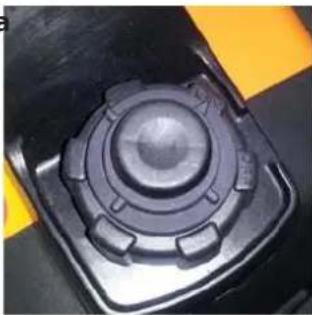
Close the tank cover until the button "OFF" displays.
natural_image
Close-up of a black mechanical component with a circular top and flanges, mounted on a black surface with yellow safety markings (no visible text or symbols)Schritt 3 / step 3 / Paso 3 / Étape 3 / Passaggio 3 Krok 3 / Kora
natural_image
Close-up of a hand using a mechanical lever on a black mechanical component (no visible text or symbols)- Vytiahnite piest pre koncového hore a zatlačte ju 3-4 krát hore a dole.
- Potegnite bat do konca navzgor in ga potisnite 3-4 krat gor in dol.
Schritt 4 / step 4 / Paso 4 / Étape 4 / Passaggio 4 / Krok 4 / Korak 4
- Starten Sie den Generator 1 - 2 Mal und dieser sollte nun starten.
-
Start the generator 1 - 2 times and this should start.
-
Inicie el generador de 1 - 2 veces y esto debe comenzar.
- Démarrez le générateur 1 - 2 fois, et cela devrait commencer.
- Avviare il generatore 1 - 2 volte, e dovrebbe partire.
- Začněte generátoru 1-2 krát, a to by mělo začít.
- Začnite generátora 1-2 krát, a to by malo začat.
- Začnite generatorja 1 - 2 krat, in to bi se moralo začeti.
Schritt 5 / step 5 / Paso 5 / Étape 5 / Passaggio 5 / Krok 5 / Kora
- Wenn der Generator startet drehen Sie die Tankdeckel Anzeige auf "ON" zurück.
- If the generator starts, turn the fuel cap indicator "ON" back.
- Si el generador se inicia, gire el indicador de tapa de combustible "ON" de nuevo.
- Si le générateur démarre, tourner l'indicateur de bouchon de carburant sur "ON" dos.
- Quando il generatore si avvia, riportare l'indicatore del tappo del carburante su "ON".
- Pokud se spustí generátor, vypněte indikátor víčko palivové nádrže "ON" záda.
- Ak sa spustí generátor, vypnite indikátor viečko palivovej nádrže "ON" chrbát.
- Če generator zažene, vključite kazalnik pokrov za gorivo "ON" zadaj.
natural_image
Close-up of a mechanical component with a circular top and flanged base, set against a yellow and black background (no visible text or symbols)INFO:
Nachdem der Generator startet stellen Sie sicher, dass die Tankdeckelanzeige zurückgesetzt ist. Andernfalls könnte nach längerem Betrieb des Generators ein Vakuum entstehen, dass den Generator zum Stillstand bringt.
✿ After the generator starts, make sure that the fuel cap indicator is reset. Otherwise could arise after prolonged operation of the generator, a vacuum that the generator to halt.
Una vez que arranque el generador, asegúrese de que se restablece el indicador de la tapa de combustible. De lo contrario, podría surgir después de la operación prolongada del generador, un vacío que el generador se detenga.
Après le générateur démarre, assurez-vous que l'indicateur de bouchon de carburant est remis à zéro. Sinon pourraient survenir après une utilisation prolongée du générateur, un vide que le générateur d'arrêter.
Dopo l'avvio del generatore, assicuratevi che l'indicatore del tappo del carburante sia azzerato. Altrimenti, dopo un funzionamento prolungato del generatore, potrebbe crearsi un vuoto che causerà l'arresto del generatore.
Po spuštění generátor, ujistěte se, že indikátor víčko palivové vynuluje. V opačném případě by mohlo dojít po delším provozu generátoru, vakuum, že generátor zastavit.
Po spustení generátor, uistite sa, že indikátor viečko palivovej vynuluje. V opačnom prípade by mohlo dôjst po dlhšej prevádzke generátora, vákuum, že generátor zastaviť.
text_image
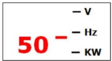
50⁻ - V - Hz - KWFrequenz (Hertz)
text_image
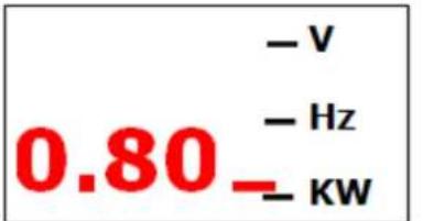
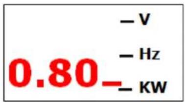
- V - Hz 0.80 - KWabgegebene Leistung
Betriebsstunden

text_image
- V - Hz 000H - KWThis manual contains important information and advice for the correct and safe use and maintenance of the FX-IG12.
Following the usual commercial name of the device (see cover) is substituted in this manual with the name "machine".
The manual is part of the machine and may not be stored separately. Read it profoundly before first use of the machine and keep it for later reference. When the machine is handed to other persons always put the manual to the machine.

Please follow the security instructions!
Due to continuous development of our products illustrations, pictures might differ slightly.
Attention!
Technical changes excepted!
Customer Support
FUXTEC GmbH
Kappstrasse 69 - 71083 Herrenberg
GERMANY
Tel.: +49 7032-95608-0
Mail : info@fuxtec.de
10 SECURITY
To ensure safe operation matters
- If you operate the FX-IG12 generator according to the guide, the generator will run safely. Please read and understand the guide without fail before you use it, or else casualties or damage of the equipment will be caused by incorrect operation.
The exhaust contains toxic CO. Do not run the generator in dead-air space. Make sure to provide enough air. - The fuel is very easy to burn or explode under specific conditions. Turn off the engine before filling.
- When filling the engine, keep away from cigarettes or spark. Please fill in a draught.
- Clean the overflowed fuel immediately.
- Each time before you start the engine, you must do check it first, avoiding accidents or damage of the equipment.
- The generator must be run at a place at least one meter away from the buildings or other equipments.
- The generator must be run on a horizontal surface. If it leans, the fuel would spill out.
- You must master the knowledge of how to turn off the generator quickly, and know all the operations of controlling the components. Do never operate the engine without correct instructions.
- Children and pets must be kept away from the operating area.
- When the engine is running, everyone must keep away from the circumvolving parts.
- The generator is a latent danger if it is incorrectly operated, so do not operate it by hand.
- Do not operate the generator in the rain or in the snow, preventing wetting it.
2.3 LABEL POSITION OF SAFETY MATTERS
These labels warn you of those latent dangers that will possibly cause serious accidents involving casualties. Please read carefully the words on the labels, the safety warnings and the notes recounted in the guide. If the labels have fallen off or are illegible, please contact the FX-IG12 agent and change them.
| 1 – Oil level label (Fig. E) | 2 – Motor switch position ON - OFF (Fig. E) |
| 3 – Warning label (Fig. F) |
11 OPERATION
11.1 Check before operation
CAUTION: The engine is delivered without oil. Fill in ca. 0.4 liter oil before starting the engine!
11.1.1 Check the oil level
- Using oil without cleanser or 2-strokes engine's oil may shorten the generator's service life.
- Please use oil containing high quantity of cleanser or use high quality 4-strokes engine's oil. The quality level must answer for or exceed the SG/SF level which is required by the American manufacturer and lay down by American Petroleum Institute.
- Please choose the engine oil with proper ropy degree based on the average temperature of the area you live in. (Fig. G)
① mono-ropy degree
② multi-ropy degree
Dismantle the machine oil ruler, rub up it with clean duster cloth, and stick it into the oil-filling mouth to check the oil level. Pay attention not to drop the ruler into it.
If the machine oil level is below the bottom of the machine oil ruler, fill the recommended machine oil into the fuel-filling mouth.

IM PORT A N T
The oil alarming system will turn off the engine before the oil level descends to the security line. But to avoid the inconvenience caused by unexpected machine halt, we advise you to check the oil level regularly.
- If the engine runs when oil is in shortage, it can be seriously damaged.
3 - Upper oil level (Fig. H)
11.1.2 Check the fuel level
Please use fuel for cars. (It's better to use no lead fuel or having low content of lead, in order to reduce the accumulation of charcoal in the burning room.)
If the fuel level is too low, please add fuel into the fuel tank until it reaches the required level.

IM PORTANT
Prevent filth, dust, or water entering the fuel tank.
Screw down the fuel-filling lid after filling the fuel.
- The fuel is very easy to burn or explode under specific conditions.
- Please fill the generator in a draught, and turn off the engine before filing. It is strictly forbidden to smoke close to the fu
- The fuel must not be spilled out of the fuel tank (the fuel-filling mouth should not have any
- fuel). Screw down the fuel-filling lid after filling the fuel.
- Be careful not to let the fuel spill out when filling the generator. The fuel overflowed or mist may take fire. Once there is some oil spilling out, make sure that the oil-spilled area is dried before starting the engine.
- Avoid exposing your skin to the fuel in a long time or repeatedly. Do not let children have contact with it.
Do never use the mixture of machine oil and fuel or uncleaned fuel.

11.1.3 Intelligent fuel-saving valve
Function:
When the engine is disconnected from the electrical equipment, the velocity of the generator will slow down automatically. When the equipment is connected, the electric charge will make the generator return to a proper rotate speed. This installation is used to reduce the fuel consumption during the running process.
On the position OFF:
It means the intelligent fuel-saving system is closed, and the rotate speed of the generator is kept on a level higher than the standard rotate speed.

When the electrical equipment needs disconnecting from the electric power, the intelligent fuel-saving system can not run effectively.
When the generator is connected with a high electric charge, turn off the intelligent fuel-saving valve to minimize the change of middle pressure.
When using the DC output, please turn off the intelligent fuel-saving valve. (Fig. D)
11.1.4 Check the air filter
Check the core of the air filter, ensuring that it is clean and performs well.
Dismantle the repair cover, loosen the screw on the cover of the air filter, and then dismantle the cover of the air filter to check the core.
Please clean or change the core if necessary.

Do not run the engine without the air filter, or else filth will enter the engine through carburetor, resulting in quick wear and tear of the engine.
| A – Screw of the repair cover (Fig. I) | B – Repair cover (Fig. I) |
| C – Air filter (Fig. J) | D – Cover of the air filter (Fig. J) |
| E – Screw of the air filter (Fig. J) | F – Core of the air filter (Fig. J) |
11.2 Start the engine
Before starting the engine, cut off the load from the alternating current socket on the engine.
a) Totally turn the valve to the "OPEN" position clockwise.
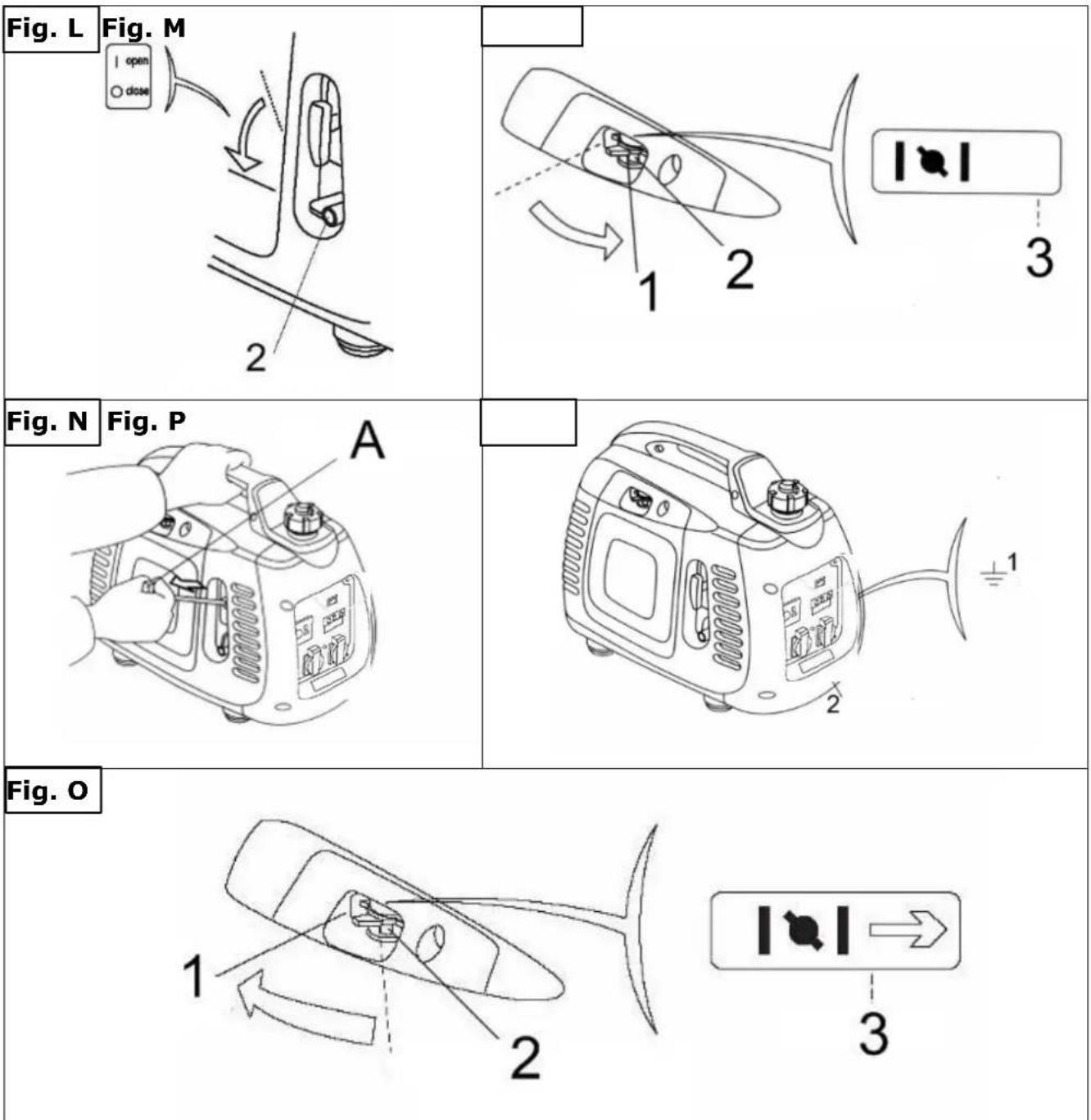
1 - The ventilating pole of fuel-filling lid (Fig. K) 2 - Switch of the engine (Fig. L)
ATTENTION: During commissioning, see note 3.3 on page 18!
b) Turn the switch of the engine to the "OPEN" position
c) Turn the pulling pole of the air-blocking valve to the "CLOSE" position

IM PORT A N T
when the engine is hot or the environmental temperature is relatively high, do not use the air-blocking valve.
1 - Close (Fig. M) | 2 - Pulling pole of the air-blocking valve (Fig. M) | 3 - Close (Fig. M)
a) Pull the starting hold (Fig. N) slightly until you feel the pressure, then release the hold slowly by hand.
b) When the engine is warming up, turn the pulling pole of the air-blocking valve to the "START" position.(Fig. O)

Do not let the starting hold (Fig. N) rebound, and release it slowly by hand.

If the engine can not restart after halting, check the oil level ahead of other failures.
1 - Run / operate (Fig. O)
2 - Pulling pole of the air-blocking valve (Fig. O)
3 - Start (Fig. O)
11.2.1 Operation at high altitudes
At high altitudes, the standard carburetor air and fuel mixture will become excessively dense, causing the decrease of the engine's functions, and increase of fuel consumption. To enhance the performance of the engine in high-altitude areas, you can make special adjustments to carburetor. If you use the engine at an altitude of over 1500 meters (5000 feet), please ask the authorized agent to modify the carburetor.

The nozzle of the engine is designed for normal altitude areas. If it is put to use in higher altitudes, the outputting power may decline and become too hot, and even the engine will be damaged seriously because the ratio of the air and burning fuel is too low.
Even though you use the proper nozzle, the horsepower of the engine will still decline 3.5% as the altitude increases every 1500 meters. If these adjustments are not made, the altitude will have greater influence on power.
11.3 Usage of the engine
In order to prevent getting an electric shock because of incorrect operation, the engine should be earthed. The earth port of the engine and the outside earth source are connected by a thick cable.
As spare electrical source for buildings, the connection between generator and other electric power system must be operated by professional electricians. And the operation must comply with
the related laws and electric regulations.
Otherwise, the current of the engine may feed back to the public circuit. In this case, if the workers from electric power company or other people touch the wire when transmitting electricity, they may be shocked by electricity to death. On the other hand, when public electricity
power is stored, the engine may burn, explode, or cause fire to the building's electric power system.

IM PORT A N T
If all the installations that are connected have been earthed, make sure to earth the engine
1 - Sign of grounding (Fig. P)
2 - Ground end (Fig. P)
- Do not exceed rated power, and the total watt of the connected electrical equipments should be considered.
- Do not exceed the fixed current limit of socket.
- Do not link the engine to the household circuit, or else the engine or the household circuit would be damaged.
- Do not modify the engine for other unrealized purposes.
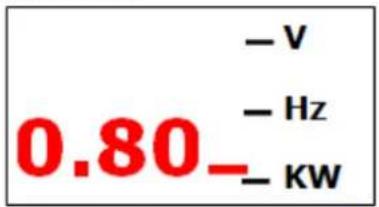
11.3.1 Display
The display changes from V, Hz, KW and hours of operation automatically.
text_image
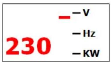
230 - -V - Hz - KWVoltage
text_image
50⁻ - V - Hz - KWFrequency (Hertz)
text_image
-V - Hz 0.80- - KWPower output
Operating hours
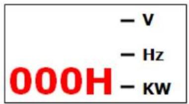
text_image
- V - Hz 000H - KW11.3.2 Use of AC alternating current
- Start the engine, and make sure the indicator light (green) is on.
- Make sure that the switch of the electrical equipment to be used has been turned off, before to plug it into the generator.
- Start the equipment
| A - Overloading indicator light (Fig. Q) |
| B - Low oil alarm (Fig. Q) |
| C - Plug (Fig. R) |
11.3.3 The outputting and overloading indicator lights
If the generator is in a good working order, the outputting indicator light (green) is on. If the generator overloads (over 2KVA), or in case of a short circuit inside the electrical machine it links to, the outputting green indicator light (2) will turn off, while the overloading indicator light (1) will lighten. At this time, the current to the linked electrical equipment will be cut off. If the red indicator light is on, you should turn off the engine, and examine why it is overloaded.
Before you link the wire to the generator, first examine if it is in good working order, and whether its electric power level exceeds the generator capacity or not. Then engage the cable of the electrical equipment and start the generator.
1 - Overload (RED) (Fig. S)
2 - Outputting (GREEN) (Fig. S)
11.3.4 Use of the continuous current
The continuous current AC socket is only applicable to charge the battery (12V).
- During the operation process of the direct current, turn the intelligent fuel-saving valve to the "CLOSE" position.
- First connected the charging cable (Fig. T) to the direct current socket of the generator
- Then link it to the junction side of the battery.
- Start the engine
- In order to prevent spark appearing around the battery, first link the charging wire to the generator, and then to the battery. The dismantlement should start from the battery.
- Before you link the charging wire to the battery which is installed on the car, first disconnect the battery's ground wire. Do not connect the battery's ground wire until the charging cable is dismantled. Such operation

ATTENTION
Do not try to start the car's engine when the generator is still connected with the batteries, or else the generator will be damaged.
The positive pole of the charging cable should not be connected to the negative pole of the battery. Do not confuse the polarity of the charging cable, otherwise serious results such as damage of the generator and the battery will be caused.
will help to prevent short circuit or spark when you contact the junction side of the battery with the car's frame or body uncarefully.
- The battery will release explosive fuel, so it must be kept away from spark, flame, or cigarettes. Please charge it in the draught.
- The battery contains acid (electrolytic cell). Once your skin or your eyes have direct contact with it, they will be burnt. Please wear exposure suit and mask.
If the electrolyte spatters on your skin, clean it with water immediately.
If the electrolyte spatters into your eyes, clean it with water immediately for at least 15 minutes, and go to the doctor at once.
If you swallow it, drink a lot of water or milk at once. Then drink magnesia latex or vegetable oil, and go to the doctor at once.

Keep the children away from it.

The electrolyte is toxic.
1 - Defender of the direct circuit (Fig. U)
2 - in ioperation -aktiv- (Fig. U)
3 - triggered -close- (Fig. U)
11.3.5 Low oil level alarming system
Low oil pressure alarming system is designed to prevent the engine being damaged by lack of machine oil in the crankcase. Before the machine oil in the crankcase declines to the security line, the low oil pressure alarming system will turn off the engine automatically. (The switch of the engine will be still in the "OPEN" position.)
After low oil pressure alarming system has closed the engine, if you operate the starter again, the low oil pressure alarming light will lighten (Fig. V), and the engine will not run. If this happens, please add machine oil.

The direct current socket can be applied when you are using alternating current.
Overloading direct circuit may make the defender of the direct current trip. (The pressed switch springs back.) If this happens, wait for a few minutes, and then press the defender again to re-operate.
11.4 Turn off the engine
Normal use:
- Turn off all the installations that are connected, and unplug the plug (Fig. W)
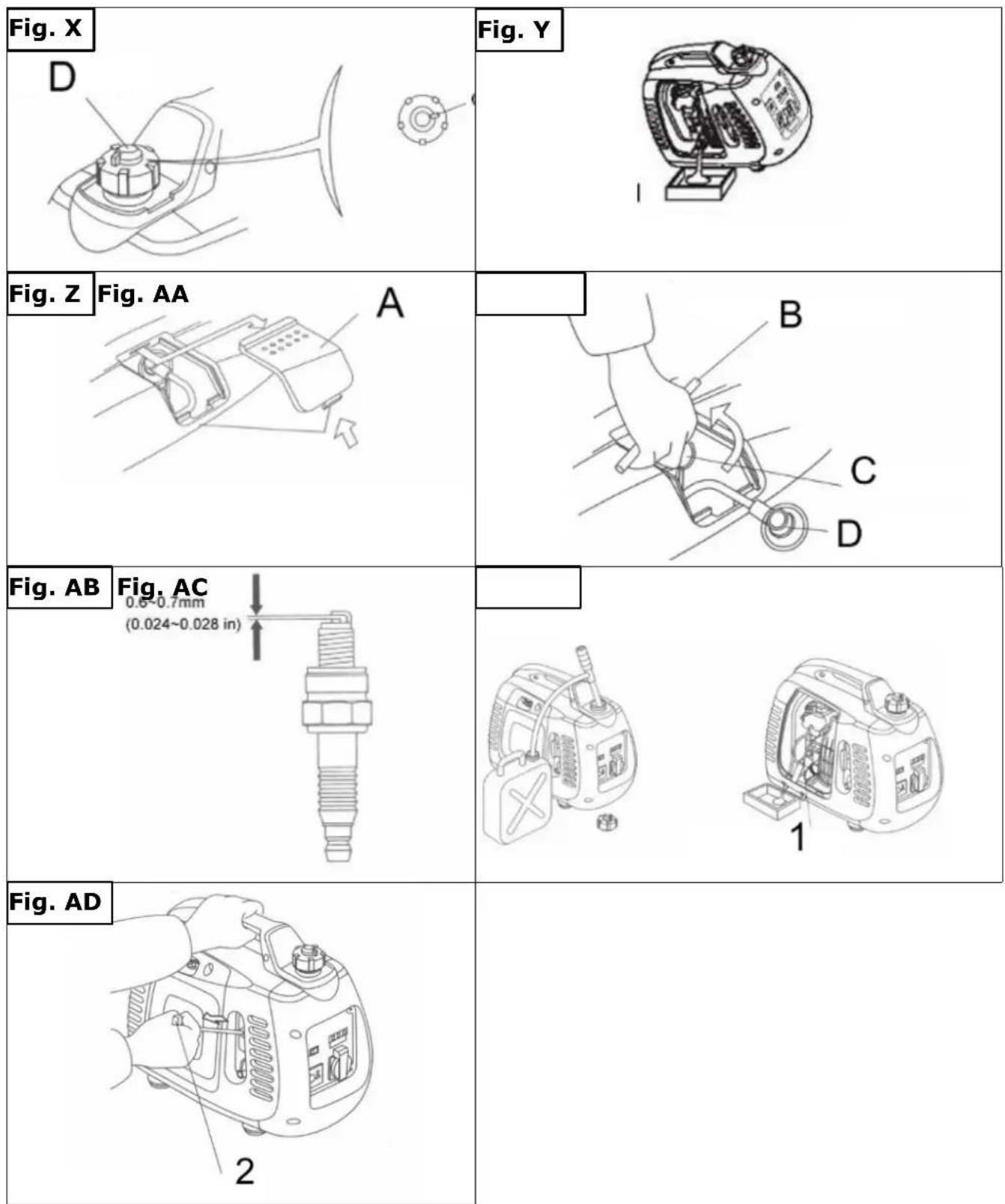
- Turn the switch (Fig. X) of the plug to the "OFF" position.
- After the engine is totally cooled, turn the ventilating pole of the fuel-burning lid to the "CLOSE" position counter-clockwise (Fig. Y).
If you want to stop the engine urgently, turn the switch of the engine to the "CLOSE" position.

IM PORTANT
12 MAINTENANCE
The purpose of making maintenance and adjustment plan is to keep the generator in the best working condition.
Please check and maintain the generator according to the plan in the following chart.
Please turn off the engine before you carry out any repair. If the engine needs to run when repairing, make sure the operating area is well ventilated, as the exhaust contains toxic CO.

ATTENTION
Please use authentic components of FX-IG12 or other substitutes with the same quality.
The unqualified components will damage the generator.
The plan chart for maintenance
Please maintain the generator in specified months or hours either month or hour is ok

IMPORTANT
(1). If used in dirty places, the generator should be maintained more regularly.
(2). Unless the user has proper tool or he is a specialist on machine, the maintenance of the above items should be done by the authorized agent. Please refer to the handbook.
(3). When it is used for business purpose, you should write down the operating hours of the generator to confirm the correct maintenance cycle.
| Itemmaintaining time by stages (1) | usage at a time | every three months or 50 hours | every six months or 100 hours | every year or 200 hours | |
| machine oil | check | O | |||
| change | O | ||||
| air filter | check | O | |||
| clean | O(1) | ||||
| spark plug | clean-adjustment | O | |||
| change | O | ||||
| clearance of air-door | check-adjustment | O(2) | |||
| fuel tank and filter | clean | O(2) | |||
| fuel route | check | every 2 years Please change if necessary | |||
-
If used in dirty places, the generator should be maintained more regularly.
-
If the user does not have the right tool, or has too little knowledge, maintenance should be performed by a qualified person.
12.1.1 Change the oil
Please discharge the machine oil quickly and thoroughly when the engine is still hot.
-
Loosen the screw, and dismantle the repair cover. (Fig. Y)
-
Dismantle the fuel-filling lid.
-
Discharge the dirty oil thoroughly into a container.
-
Fill the recommended machine oil, and check the machine oil level.
-
Re-install the repair cover and screw the screw.
12.1.2 Maintenance of the spark plug
Recommended spark plug: A7RC or NGK R7HSA
To ensure the engine to work in good order, the clearance of the spark plug must be correct, and has no accumulated charcoal.
-
Dismantle the repair cover of the spark plug (Fig. Z).
-
Dismantle the cap of the spark plug.
-
Clean out the filth around the base of the spark plug.
-
Dismantle the spark plug with a spanner.

ATTENTION
Before you discharge the oil, make sure the switches on the ventilating pole of the fuel-burning lid and the engine are on the "close" position.

ATTENTION
The spark plug must be fixed firmly, or else it will become very hot and damage the generator.
Do not use the spark plug whose thermal measurement range is not suitable.
| B – Hold of the handle (Fig. AA) |
| C – Banner of the spark plug (Fig. AA) |
| D – Cap of the spark plug (Fig. AA) |
- Examine the spark plug with your naked eyes. If the insulator has crazed or has fragments, you should discard the spark plug. If the old spark plug needs to be used continually, you must clean it up with a brush.
- Measure the clearance of the spark plug with a gauge. The clearance should be 0.6nm to 0.7nm. (Fig. AB)
- Install the spark plug carefully by hand. Pay attention not to overlap the screw thread.
- After installing a new spark plug by hand, screw it with a spanner for a half circle in order to press the washer tightly. If an old spark plug is installed, you only need to screw it from one eighth circle to one fourth circle after it is fixed.
- Re-install the cap of the spark plug.
12.2 Transport / Storage
In order to avoid the generator leaking oil during transport or temporary storage, make sure to switch off the generator, keeping it at a standing pose under normal operations. After the engine is totally cooled, turn the ventilating pole of the fuel-filling lid to the "close" position thoroughly.
When transporting the generator:
- Do not let the fuel spill out of the fuel tank. (The top of the fuel-filling tank should have no fuel.)
- When the generator is placed on vehicle, do not run the engine. You should take the generator down from the car and operate it in the draught.
- When you take the generator to the car, avoid exposing it to sunshine. If it is put in sealed carriage for a long time, the high temperature of the carriage may cause the fuel to boiling away, thus leads to burn.
- The cars loaded with generator should not bump on the uneven roads for a long time. If it has to travel on such roads, the fuel in the fuel tank should be discharged thoroughly in advance.
Before the generator is put into a long-time storage, you should:
- Make sure the storage area is clean and dry.
- Discharge the fuel thoroughly:
A. Discharge the fuel in the fuel tank thoroughly into a proper container
B. Turn the switch of the engine to the "OPEN" position. Dismantle the oil-discharging screw (Fig. AC) on the carburetor and discharge the fuel in it into a proper container.

Fuel is very easy to burn or explode under specific conditions.
Smoke and flame are strictly forbidden near the fuel.
C. Screw down the oil-discharging screw on the lid of the spark plug. Pull the starting hold for three or four times, and discharge the fuel from the oil-spouting pump.
D. Turn the switch of the engine to the "CLOSE" position. Then screw the oil-discharging screw tightly.
E. Re-install the cap of the spark plug on the spark plug.
- Discharge the machine oil.
- Dismantle the spark plug, and pour a big spoon of clean machine oil into the engine. Make the engine rotate for several circles to make the oil evenly distribute. Install the spark plug again.
- Pull the starting hold (Fig. AD) slowly until you feel the resistance. At this time, the piston reaches the compressed stroke, and both the entering and the discharging valve are closed. To store the generator under such condition will help to prevent the inside of the machine rusting.
12.2.1 Cleaning

NOTICE
The usage of certain solutions containing ingredients damaging metal surfaces as well as the use of scrubbing agents will damage the machine surface!
Clean the machine surface with a wet cloth soaked in a mild solution
Clean the machine from mud and grass after every operation:
Protect non coated metal parts against corrosion (e.g. with oil or WD40)!
12.2.2 Storage
If the generator is stored for longer than 30 days:
- Wait until the engine cools down sufficiently.
- Allow the fuel from the tank into a suitable container and store the drained fuel in a suitable container.
- Clean and dry machine
- Store in a dry, out of reach of children place, well wrapped (cut protection)
- Cover the machine well and store it in a dry and clean place.
12.2.3 Disposal
Do not dispose the machine in residual waste. Contact your local authorities for information regarding the available disposal options. When you buy at your local dealer for a replacement unit, the latter is obliged to exchange your old.

13 SPARE PART ORDER
With original FUXTEC spare parts you use parts that are attuned to each other and shorten the installation time and elongate your machines lifespan.
IM PORTANT
The installation of non-original parts renders warranty null and void.
Exempted is the replacement of the spark plug if carried out by a specialist.
You find the order address in the preface of this operation manual.
14 PREFACIO (ES)
Estimado cliente,
text_image
50⁻ - V - Hz - KWfréquence (Hertz)
text_image
- V - Hz 0.80- - KW20.2 Transport / stockage
text_image
- V - Hz - KW 50 - (Frequenza (Hertz)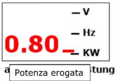
text_image
-V - Hz 0.80- - KW a Potenza erogata tungOre di servizio
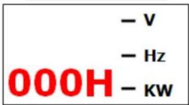
text_image
- V - Hz 000H - KWHereby we declare that the above mentioned machines meet the essential safety and health requirements of the above stated EC directives. Any manipulation or change of the machine not being explicitly authorized by us in advance renders this document null and void.
text_image
Tian GumpreTim Gumprecht
Company FUXTEC Maschinen GmbH grants for mechanical and electrical components a warranty period of 2 years for amateur use; and warranty period of 1 year for professional use, starting with the purchase of the final consumer. In case of defects during this period, which are not excluded by paragraph 3, FUXTEC will repair or replace the machine at its own discretion.
2.) Report:
In order to check the legitimacy of warranty claims, the final consumer must contact his dealer. The dealer has to report in written form the occurred defect to FUXTEC. If the warranty claim is legitimate, FUXTEC will pick up the defective machine from the dealer. Returned shippings by dealers which have not been coordinated with FUXTEC, will not be accepted and refused.
3.) Regulations:
a) Warranty claims will only be accepted, when a copy of the original invoice or cash voucher from the trading partner of FUXTEC is enclosed to the machine. The warranty claim expires if the accessories belonging to the machine are missing.
b) The warranty does not include free checking, maintenance, inspection or service works on the machine. Defects due to incorrect usage of the final consumer or his dealer will not be accepted as warranty claims either. Some examples: usage of wrong fuel, frost damages in water tanks, leaving fuel in the tank during the winter, etc.
c) Defects on wear parts are excluded, e.g. carbon brushes, collection bags, knives, cylinders, cutting blades, clutches, sealings, wheels, saw blades, splitting crosses, riving knives, riving knife extensions, hydraulic oils, oil/air/fuel filters, chains, spark plugs, sliding blocks, etc.
d) Also excluded are damages on the machine caused by incorrect or inappropriate usage, if it was used for a purpose which the machine is not supposed to, ignoring the user manual, force majeure, repairs or technical manipulations by not authorized workshops or by the customer himself, usage of non-original FUXTEC spare parts or accessories.
e) After inspection by our qualified personnel, resulted costs (like freight charges) and expenses for not legitimated warranty claims will be charged to the final customer or dealer.
f) In case of defective machines outside the warranty period, we will only repair after advance payment or dealer's invoice according to the cost estimate (incl. freight costs) of FUXTEC.
g) Warranty claims can only be granted for customers of an authorized FUXTEC dealer who directly purchased the machine from FUXTEC. These claims are not transferable in case of multiple sales of the machine.
4.) Claims for compensation and other liabilities:
The liability of company FUXTEC is limited to the value of goods in all cases. Claims for compensation because of poor performance, lacks, damages or loss of earnings due to defects during the warranty period will not be accepted. FUXTEC insists on its right to subsequent improvement of the machine.
39 GARANTÍA Y SERVICIO
1.) Garantía:
Product experience form
We observe the quality of our delivered products in the frame of a Quality Management policy.
Your opinion is essential for further product development and product choice. Please let us know about your:
- Impressions and suggestions for improvement.
- experiences that may be useful for other users and for product design
- Experiences with malfunctions that occur in specific operation modes
We would like to ask you to note down your experiences and observations and send them to us via FAX, E-Mail or by post: