FXSG7500B - Generator Fuxtec - Free user manual and instructions
Find the device manual for free FXSG7500B Fuxtec in PDF.
| Brand | Fuxtec |
| Model | FXSG7500B |
| Product type | Gasoline generator |
| Engine type | 4-stroke OHC single-cylinder air-cooled |
| Displacement | 420 cm³ |
| Maximum power | 9.2 kW (at 3600 rpm) |
| Rated power | 6.0 kW |
| Rated voltage | 230 V / 400 V |
| Frequency | 50 Hz |
| Starting system | Manual (recoil) and electric (key) |
| Fuel | Unleaded premium 95 |
| Tank capacity | 28 L |
| Engine oil | FUXTEC SAE 30 (capacity 1.1 L) |
| Fuel consumption | 3.33 kg/h |
| Battery (optional) | 12 V, max charging current 8.3 A |
| Dimensions (L x W x H) | 740 x 555 x 620 mm |
| Net weight | 94 kg (with electric start) |
| Sound pressure level | 74 dB(A) |
| Guaranteed sound power level | 97 dB(A) |
| Operating temperature range | -5 °C to +40 °C |
| Max operating altitude | 1500 m |
| Humidity | 90% at 25 °C |
| Spark plug | Transistorized non-contact ignition, gap 0.7-0.8 mm |
| Outlets | 1 x 230 V, 1 x 400 V, 1 x 12 V DC |
| Protections | AC safety switch, DC circuit breaker, low oil level shutdown |
| Delivery contents | Generator, instruction manual |
Frequently Asked Questions - FXSG7500B Fuxtec
User questions about FXSG7500B Fuxtec
0 question about this device. Answer the ones you know or ask your own.
Ask a new question about this device
Download the instructions for your Generator in PDF format for free! Find your manual FXSG7500B - Fuxtec and take your electronic device back in hand. On this page are published all the documents necessary for the use of your device. FXSG7500B by Fuxtec.
USER MANUAL FXSG7500B Fuxtec
natural_image
Illustration of a yellow industrial machine with visible internal components and wheels (no text or symbols)natural_image
Simple line drawing of a container with liquid and a funnel, no text or symbols present


Stellungen
Chokehebel (gelb)
text_image
13 14 15 21 20 19 18 17 16 Designed for the following: A-PM-14 (in miles): - Emissions/Transmission - CO2 / CO2 - Control voltage bus - Power source / GB - GB - Data, sec. HUB - GB - Power source / GB Pt Cautionnatural_image
Close-up of a mechanical device with orange frame and red directional arrows indicating motion, no visible text or symbols.
HINWEIS
natural_image
Close-up of a black FUXTEC air conditioner unit with red arrows indicating airflow direction (no text or symbols on the device itself)text_image
A Designed for the following: 6-PB-50 (12) 100% 100% Pb CE E D Ctext_image
Diagnation and Resistance 6-PDM-142 (100%) Diagnation and Resistance with 30°C - Electrical Field - Electrical Field - Power - Power - Power - Power - Power - Power - Power - Power - Power - Power - Power - Power - Power - Power - Power - Power - Power - Power - Power - Power - Power - Power - Power - Power - Power - Power - Power - Power - Power - Power - Power - Power - Power - Powertext_image
RVR RVR FUXTEC FUXTEC RVRtext_image
START CLOSE RUN OPEN
HINWEIS
natural_image
Close-up of a black FUXTEC air compressor unit with visible fan and control panel (no text or symbols on main body)text_image
VAS RVR RVR RVR RVR RVR RVR RVR RVR RVR RVR RVR RVR RVR RVR RVR RVR RVR RVR RVR RVR RVR RVR RVR RVR RVR RVR RVR RVR RVR RVR RVR RVR RVR RVRtext_image
Technical diagram of a mechanical device with labeled components and directional arrows, including a magnified inset showing a tank component.natural_image
Close-up of a mechanical engine component with orange tubing and a red arrow pointing to a yellow Y-shaped component (no text or symbols visible)natural_image
Close-up of a mechanical engine component with orange hoses and a red arrow indicating a specific part (no visible text or symbols)i HINWEIS!
Symbols on the power generator 21
For your safety 23
At a glance....28
Technical data 30
Before commissioning....32
Operation 33
Maintenance and care 36
Troubleshooting 38
CE-Conformity 39
Symbols used

WARNING!
Indicates an imminent danger. Failure to observe this warning may result in death or severe injury.

CAUTION!
Indicates a potentially dangerous situation. Failure to observe this warning may result in injury or damage to property.

NOTE
Indicates application tips and essential information.
Symbols on the generator
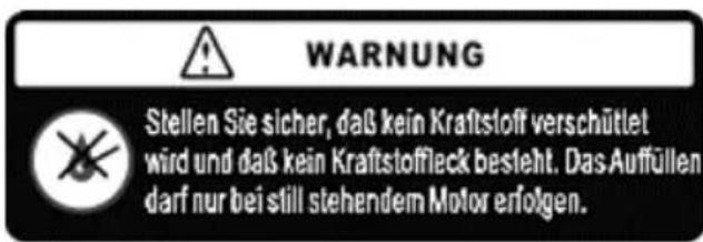
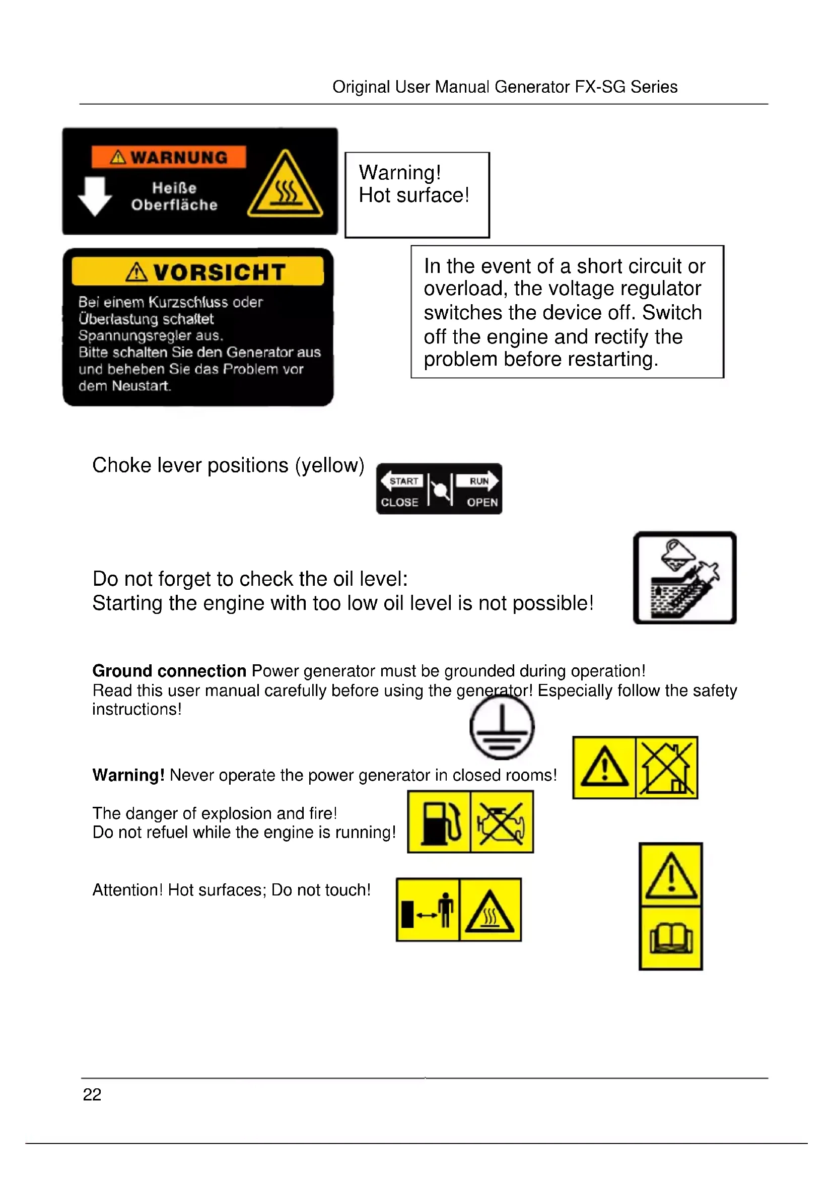
Warning: Do not refill fuel during operation. Do not spill fuel - fire hazard
Air filter maintenance:
- Check after 20h of operation
- Use soft Cleaning agents
- Dry Filter completely till next use

Warning! Hot surface!
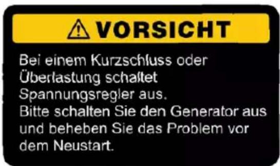
In the event of a short circuit or overload, the voltage regulator switches the device off. Switch off the engine and rectify the problem before restarting.
Choke lever positions (yellow)

Do not forget to check the oil level: Starting the engine with too low oil level is not possible!

natural_image
Simple line drawing of a container with liquid and a funnel, no text or symbols presentGround connection Power generator must be grounded during operation! Read this user manual carefully before using the generator! Especially follow the safety instructions!

Warning! Never operate the power generator in closed rooms!

The danger of explosion and fire! Do not refuel while the engine is running!

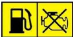
Attention! Hot surfaces; Do not touch!


Attention!
Maximum noise level 97 dB!

Fuel shut-off valve positions
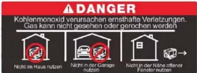
Do not use indoors! Do
not use it in the garage!
Do not use near open windows!

WARNING!
Before using the power generator, read and act upon
- this user manual,
– the rules and regulations for occupational health and safety and accident prevention applicable to the
For your safety
User
■ The generator is not intended to be used by persons with reduced physical, sensory or mental capabilities or lack of experience and knowledge.
■ Never allow children or persons unfamiliar with the following instructions to use the generator.
■ Ensure that children and unauthorized persons do not come into contact with the generator.
Intended use
The power generator is exclusively intended:
- For generating current in the voltage ranges specified under "Technical data,"
- For use following the descriptions and safety instructions given in this user manual.
■ The user/operator and not the manufacturer is liable for any damage or injury resulting from misuse. Only the spare parts and accessories specified for these generators may be used.
■ Part of the intended use is observing all safety instructions and operating notes in the user manual. Persons who operate and maintain the generator must be familiar with it and must know and observe all possible dangers.
■ Also, applicable accident prevention regulations must be strictly observed.
■ The general occupational health and safety regulations must be strictly observed. The power generator is only intended for use in open, well-ventilated areas.
■ Any other use is not following the regulations.
■ Improper use will void the warranty, and the manufacturer will not be held responsible.
■ The user is liable for all damages to third parties and their property.
■ Operate the device only in the technical condition specified and delivered by the manufacturer.
■ Unauthorized modifications to the device will void the manufacturer's liability for any resulting damage and will void the warranty.
General safety instructions

WARNING!
Read all safety notes and instructions.
Failure to comply with the safety instructions may result in fire and serious injury.
Keep all safety notes and instructions for future reference.
■ Never run the engine of the power generator in closed rooms or buildings. The exhaust gases contain dangerous carbon monoxide.
For operation in well-ventilated rooms, additional measures must be taken to protect against fire and explosions - e.g., provide suitable fire extinguishers.
■ Only operate the generator within the temperature range specified in this user manual.
■ Have all maintenance work on the generator, except for the work listed in this operating manual, performed by authorized and qualified maintenance personnel.
■ Always switch off the generator before carrying out any assembly, adjustment, or maintenance work.
■ Note that improper maintenance, non-conforming spare parts, or the removal or modification of safety devices can cause damage to the device and severe injury.
■ Make sure that the power supply does not get into the hands of unauthorized persons or children!
■ Be aware that national regulations may restrict the use of the generator.
■ Check the generator for significant damage and defects before each use.
■ If necessary, have your specialist dealer instruct you before using the generator.
■ Only use the spare parts and protective devices specified by the manufacturer. Other spare parts and accessories will invalidate the warranty and permanently increase the user's risk of injury.
■ Always keep the generator in good technical operating condition.
■ Do not operate the generator in a humid environment. Protect the electrical and electronic components from the effects of moisture.
Electrical safety
■ Ensure that connected electrical devices, including the power cable and plug connections, are technically perfect.
■ Ensure that the following total cable length is not exceeded when using extension cables or mobile distribution networks:
- 60 meters for a cable cross-section of 1.5 ~mm^2
- 100 meters for a cross-section of 2.5 ~mm^2 .
■ Please note that the power generating sets' generators can only be loaded up to their rated capacity under the specified operating conditions!
■ The generator load must be restricted if the engine and generator cooling is limited due to the following factors:
– Operation in confined spaces
– Exceeding/falling below the temperature operating range
– Exceeding the max. operating height
– Exceeding the max. humidity range
■ Never connect the generator to the mains supply yourself.
■ Risk of injury from electrical voltage!
Have installation, repair, and maintenance work on the engine, generator, and electrical and electronic components of the power generator carried out exclusively by trained and authorized personnel.
The danger of suffocation due to carbon monoxide!
■ Do not operate the power generator in closed rooms. Engine exhaust gases are highly toxic. Inhalation of odourless carbon monoxide can lead to death!
■ When operating in well-ventilated rooms, additional measures must be taken to protect against fire and explosions!
Explosion and fire hazard!
Gasoline vapours are explosive, and gasoline is highly flammable.
■ Fill with fuel before starting the engine. Keep the tank closed while the engine is running or still hot.
■ Never refuel during operation.
■ Only fill up with fuel when the engine has been switched off and cooled down. Avoid naked flames, sparks and do not smoke. Refuel the device outdoors only.
■ Do not start the engine if fuel has overflowed. Move the generator away from a fuel-contaminated surface. Wait until the fuel vapours have evaporated.
■ To prevent fire hazards, keep the following parts free of leaking oil or fuel:
- Engine,
- Exhaust,
- gasoline tank.
Workplace safety
- Keep the location of the power tool, clean and well-lit. Untidy or unlit areas can lead to accidents.
■ Do not operate the generator in potentially explosive atmospheres.
That applies in particular to locations in which flammable liquids, gases, or dust are present.
■ Keep children and other unauthorized persons away from the operating site during operation.
Safety of persons
■ Be alert, pay attention to what you are doing, and use common sense when working with the generator set.
■ Do not operate a generator when you are tired or under the influence of drugs, alcohol, or medication.
A moment of carelessness when connecting and starting up the generator can lead to severe injuries.
■ Wear protective gloves and, if necessary, safety goggles, depending on the circumstances, during start-up, maintenance, and repair work. Taking appropriate personal protective measures reduces the risk of injury.
Residual hazards
Even if the power generator is used correctly, there is always a residual risk that cannot be excluded. The following potential hazards can be derived from the type and design of the power generator:
- Contact with electrical connections and components of the power generator (electric shock),
-
Unforeseen, sudden defects in moving parts of the power generator,
-
Damage to the hearing, if no prescribed hearing protection is worn during continuous operation,
– Inhalation of exhaust gases from the combustion engine,
– skin contact with gasoline.
Additional safety instructions
■ Switch off the generator under the following conditions:
– Before filling up with fuel (let components cool down first),
- if it is left unattended for a more extended period,
– before checking, cleaning, or otherwise working on the generator,
- if the Genset starts to vibrate excessively.
■ During operation, ensure that no persons (especially children) or animals are in the operating area.
■ Only use the generator set under dry conditions. Keep the unit away from rain and moisture.
■ Do not leave the generator unattended during longer breaks in operation, and park the generator after the process in a secure location that is not accessible to unauthorized persons.
■ Always switch off the generator when transporting it to other operating locations.
■ Make sure that all protective devices are mounted when using the generator.
■ Never operate an incompletely assembled generator or a generator with unauthorized modifications.
■ Only operate the generator in the technical condition specified and supplied by the manufacturer.
Unauthorized modifications to the generator exclude the manufacturer's liability for any resulting damage.
■ Only use original spare parts or spare parts approved by the manufacturer.
Observe the installation instructions supplied with the replacement parts.
■ Only have repairs carried out by a qualified and authorized specialist or a specialist workshop.
■ Take the following measures before commissioning:
- Carry out a visual inspection for damage.
- Check the generator for loose parts and, if necessary, remedy the situation by reassembling the pieces correctly.
- Have damaged parts replaced or repaired. Make sure that the replacement parts are of the correct specification.
■ Before operating the generator, familiarize yourself thoroughly with its operation and, if necessary, have a specialist instruct you.
Noise and vibration
i NOTE
Refer to the "Technical data" table for the A-weighted noise level and the total vibration values.
CAUTION!
The measured values given apply to new devices. Noise and vibration values change during daily use.
NOTE
The vibration level specified in these instructions has been measured in accordance with a standardized measuring method in EN 60745. If the power supply is insufficiently maintained, the vibration level may deviate during operation.
That can significantly increase the vibration load over the entire working period.

CAUTION!
Hearing protection must be worn if the sound pressure exceeds 85 dB(A).
Information on noise generation

CAUTION!
The actual vibration emission value during the current collector's use may deviate from the value specified in the operating instructions or by the manufacturer. This can be caused by the following influencing factors, which should be considered before or during use:
– Is the generator being used as intended?
- Are the commissioning and operating procedures correct?
- Are the condition of the generator and its functional components correct?
- Are all safety devices in safe operating condition?

NOTE
There may be national regulations (environment, occupational health, and safety) that restrict the generator's use. Use of the generator.
Noise pollution from this device cannot be avoided.
■ Postpone noisy work to approved and designated times and areas.
■ Wear appropriate hearing protection for personal protection.
■ Instruct persons in the vicinity of working in the emission area to wear hearing protection.
At a glance
text_image
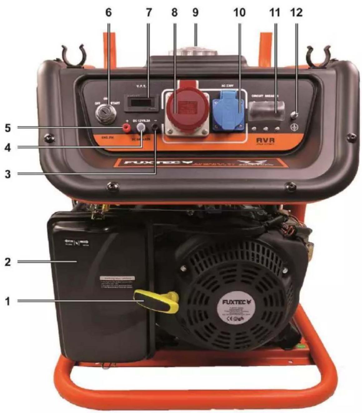
1 2 3 4 5 6 7 8 9 10 11 12 FUXTEC AVR CIRCUIT MEAN V.F.T. OFF START DC 12V/8.3A AC 3KW ENQ SW DC SHAKLE FUXTEC FUXTEC1 Handle with cable pull
2 Air filter housing
3 Minus pole charging cable connection
4 DC reset button
5 Positive pole charging cable connection
6 Key switch electric start (FX-SG7500B only)
7 Display
8 400 V socket
9 Fuel tank cap
10 230 V socket
11 AC fuse switch
12 Ground connection
text_image
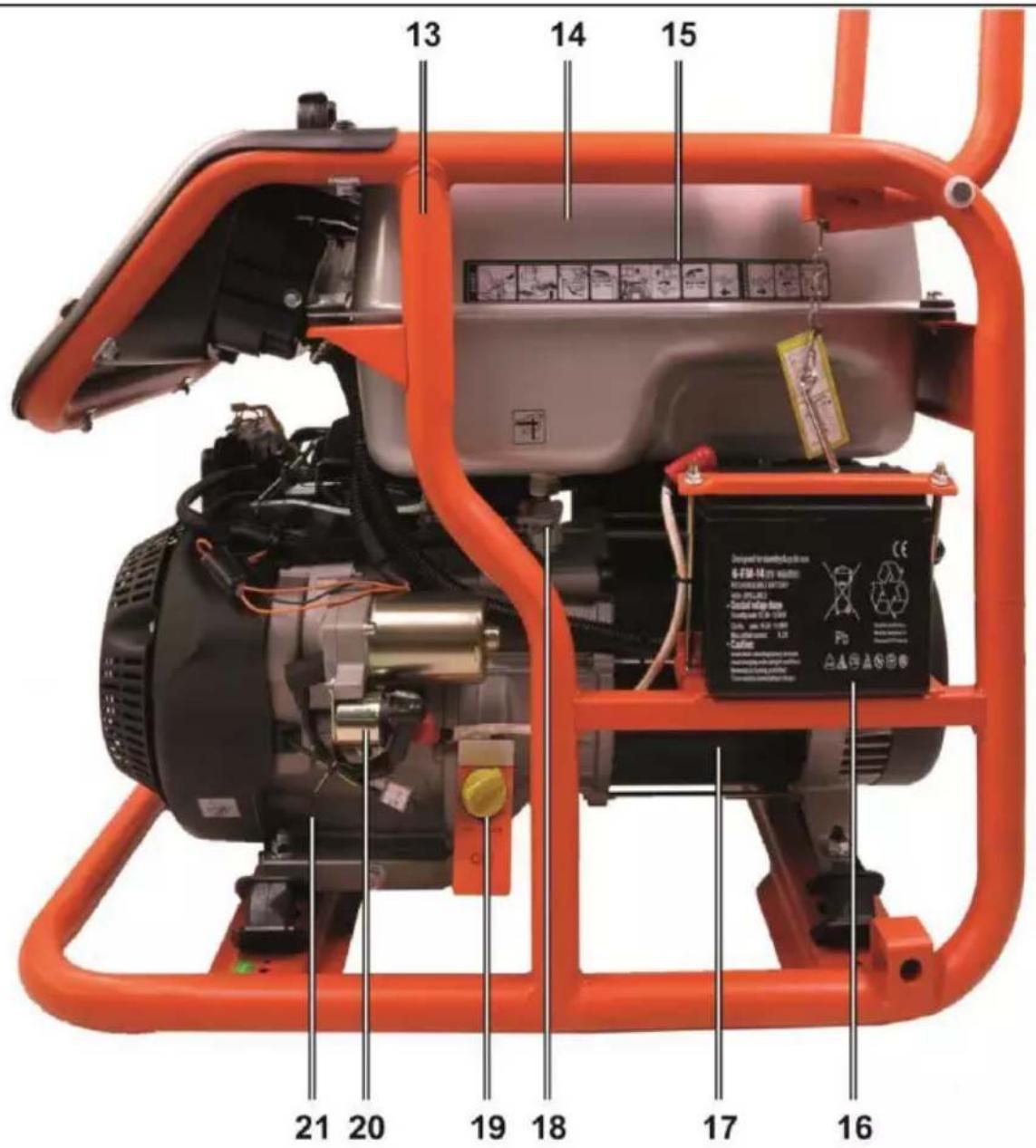
13 14 15 21 20 19 18 17 16 Dengyat transdered battery 6-FM-H19 power RHYPERATION & BATTERY NON-SPRING • Model HPSB block Cable: 1.0 GB • Cable: 1.0 GB Pb CE AHAAN®13 Rack
14 Fuel tank
15 Quick start/stop guide
16 Starter battery (FX-SG7500B only)
17 Generator side
18 Fuel shut-off valve
19 Oil filler cap
20 Electric starter (FX-SG7500B only)
21 Side of the engine
text_image
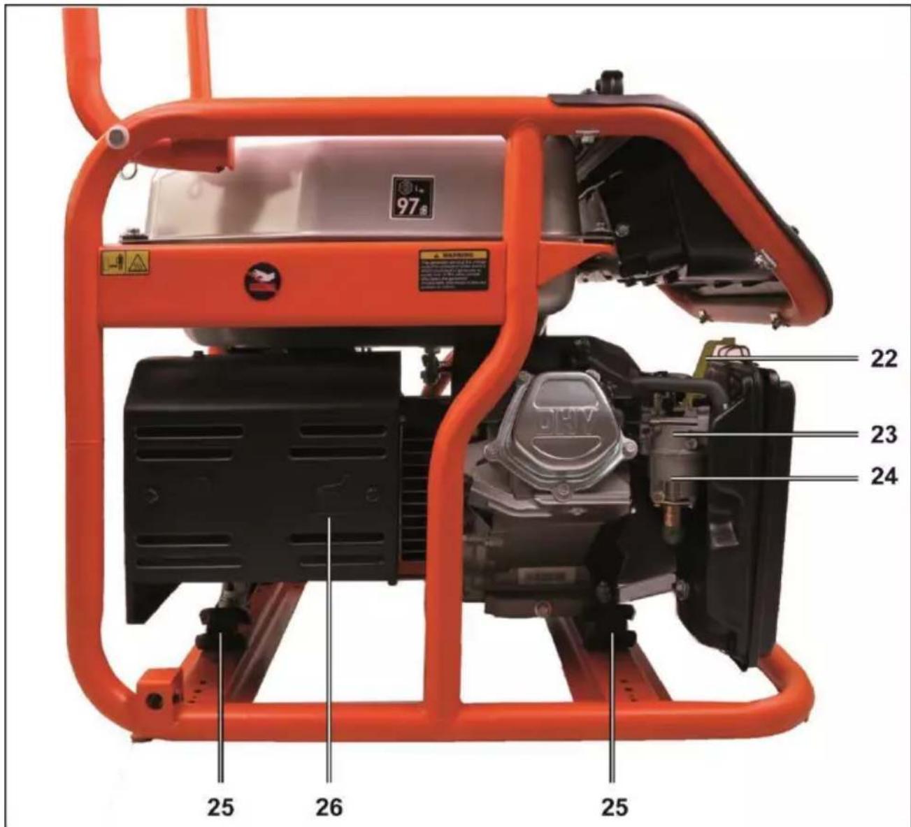
97 WARNING 22 23 24 25 26 2522 Choke lever
25 Damping element
23 Carburettor
26 Oil filler cap
24 Oil filter cup with filter
Technical data
| Designation | Unit | Type/Value | |||
| Generator model | FX-SG3800 | FX-SG7500/7500A/7500B | |||
| Engine type | 4-stroke OHC; an air-cooled 1-cylinder engine | ||||
| Displacement | cm^3 | 208 | 420 | ||
| Engine oil | FUXTEC SAE 30 | ||||
| Maximum power output | kW/min-1 | 4.7/3600 | 9.2/3600 | ||
| Ignition system | - | Transistor ignition without contact | |||
| Starting system | - | Manual / electric for FX-SG7500B | |||
| Fuel | Super gasoline95 octane | ||||
| Fuel tank capacity | I | 13 | 28 | ||
| Spark plug | Transistor ignition without contact | ||||
| Fuel consumption | kg/h | 1.77 | 3.33 | ||
| Engine oil capacity | I | 0.6 | 1.1 | ||
| Measured sound pressure level | dB(A) | 73 | 74 | ||
| Measured sound power level | dB(A) | 95 | 96 | ||
| Engine data | |||||
| Guaranteed sound power level | dB(A) | 96 | 97 | ||
| Uncertainty | (K) | 1.5 | 1.5 | ||
| maximum insertion height | m | 1500 | |||
| Temperature application range | °C | min. / max: -5 / +40 | |||
| Humidity | 90% / at 25°C | ||||
| Generator data | |||||
| Rated frequency | Hz | 50 | |||
| Nominal voltage | V | 230 / 400 | |||
| Rated power | kW | 2.8 | 6.0 | ||
| Generator set | |||||
| Length | mm | 635 | 740 | ||
| Width | mm | 455 | 555 | ||
| Height | mm | 525 | 620 | ||
| Dry weight | kg | 53/55 | 89/91 | 87/90 | 94/97 |
| Charging | No self-charging | ||||
| Battery voltage (DC) | VDC | 12 | |||
| Battery max. charging current (DC) | A | 8.3 | |||
| Battery (optional) | ||
| Model | Voltage / max. charging current | Remark |
| FX-SG7500B | 12 VDC / 8.3 A | use maintenance-free battery |
Before commissioning
Check the power generator for completeness of delivery and transport damage.

NOTE
Immediately report any damage to the generator or defective or missing parts to the supplier or manufacturer!
Scope of delivery
The scope of delivery includes
- Power generator set
- User manual
Inspection work

WARNING!
Before carrying out any work on components, secure the power generator on a flat, stable surface and protect it against unauthorized switches.

CAUTION!
Do not start up the power generator until you have carried out all the necessary assembly, adjustment, and inspection work on the power generator have been carried out.
Checking the engine oil level

natural_image
Close-up of a mechanical device with orange frame and control panel, showing internal components and directional arrows (no text or symbols visible)The engine will not start if the engine oil level is too low.

NOTE
Make sure that no oil flows next to it when topping up engine oil. Wipe off leaks so- fort with clean rag.
■ Unscrew the oil filler cap together with the oil dipstick from the filler neck and pull it out. Clean the dipstick with a clean cloth.
■ Insert the dipstick into the oil filler neck without screwing it in.
■ If the oil level is below the lower limit mark, fill the recommended oil up to the upper limit mark.
■ Screw the oil filler cap firmly back onto the oil filler neck.
Filling up with fuel

DANGER!
Pay special attention to the safety instructions in the chapter "Explosion and fire hazard" as well as to the safety stickers on the generator!
■ Unscrew the cap on the fuel tank.
- Check the filling level. If necessary, fill the tank to a maximum of the upper edge of the filter.
■ Screw the fuel tank cap tightly back onto the fuel tank nozzle.
Checking the air filter
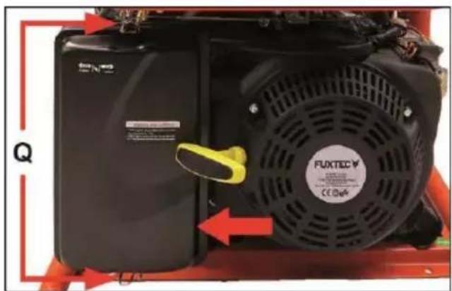
natural_image
Close-up of a black FUXTEC air purifier unit mounted on a red industrial machine, with no visible text or symbols.■ Loosen the clamping straps (Q) at the top and bottom of the air filter housing.
■ Check the condition of the air filter; replace the air filter if it is damaged.
■ Clean the air filter if it is dirty as follows:
- Wash the filter element in the washing solution.
- Allow the filter element to dry.
- Wet the filter element with acidic engine oil.
- Squeeze excess engine oil out of the filter insert.
■ Replace the filter insert in the filter housing and secure the filter insert by fastening the filter cover with the clamping straps.
Battery (optional) - FX-SG7500B only
Mounting the battery
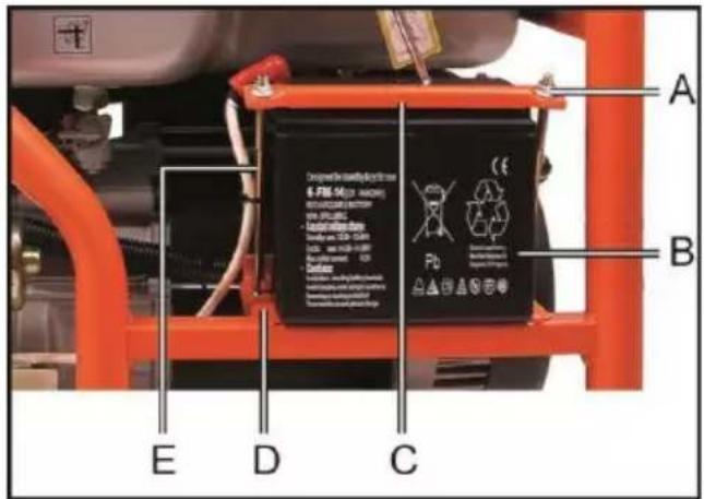
text_image
A B C D E Pb CE - 6-PB6-50 (200-1000V) - 400-1000-1000V - 1000-1500-2000V - 2000-2500-3000V - 3000-3500-4000V - 4000-4500-5000V - 5000-5500-6000V - 6000-6500-7000V - 7000-7500-8000V - 8000-8500-9000V - 9000-9500-1000V - 10000-1100V - 1200V - 140V - 160V - 180V - 200V - 220V - 240V - 260V - 280V - 300V - 320V - 340V - 360V - 380V - 400V - 420V - 440V - 460V - 480V - 500V - 520V - 540V - 560V - 580V - 600V■ Mount the battery (B) at the designated location.
■ Attach the battery to the support (D) using the clamping plate (C), mounting bolts (E), and nuts (A).
Connecting the battery
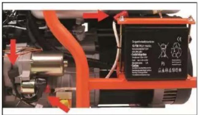
■ Connect the positive wire (red) of the generator with the electric starter to the starter motor.
■ Connect the ground connection (black) to the back of the generator.
■ Connect the generator's terminal with the electric starter first to the battery's positive terminal and then to the negative terminal.
When disconnecting, remove the connection from the negative terminal first and only then from the positive terminal.
Check electrolyte level
i NOTE
Check that there is sufficient electrolyte in the battery cells.
The electrolyte level must be between the UPPER and LOWER markings.
■ Top up electrolyte when the electrolyte level is below the LOWER mark.
■ After you have topped up the electrolyte, wait 20-30 minutes.
NOTE
The generator cannot be started until this time has elapsed.
Operation
WARNING!
Switch off the generator under the following conditions:
- if the power generator is left unattended for an extended period,
– before checking, cleaning, or other work on the power generator, - if the generator begins to vibrate excessively.
Preparing for operation
CAUTION!
Ensure that no loads are connected to the are connected to the 230 V and 400 v sockets!
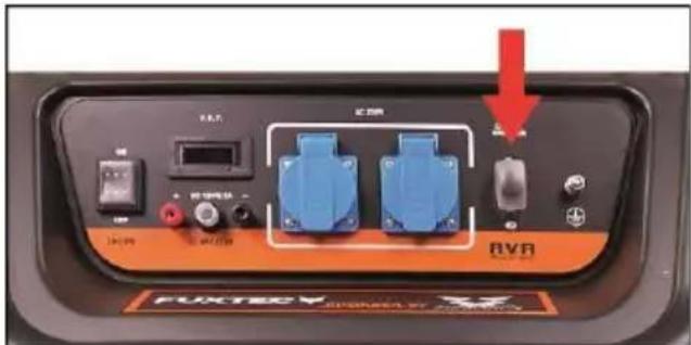
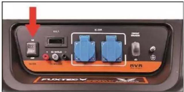
AC fuse switch
text_image
FURTEO FURTEO■ Switch the AC fuse switch to the "ON" position.
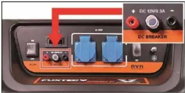
DC-DC connection for charging an external battery
text_image
DC 12V/8.3A DC BREAKER EFFECTEDThis function is intended for the external charging of a 12 V battery.

CAUTION!
The 12 V battery may only be charged when it is removed.
■ Press the DC to reset critical (12V overload protection).
Check or observe the following:
■ If the DC Reset (12V overload protection) is pressed.
■ The generator must not be in operation.
■ When connecting the battery, pay attention to the polarity of the charging cable and the battery.
- Cable: Red = Plus (+) - Cable: Black = Minus (-)
■ Observe the battery manufacturer's charging instructions.
■ Insert the charging plug of the charging cable into the 12 V socket of the generator.
■ Start the generator - the battery is charged.

CAUTION!
After the charging process is completed, first switch off the generator and only then disconnect the battery!

WARNING!
Flammable gases develop when charging a battery.
- Therefore, make sure that there is sufficient ventilation during the charging process.
- Keep all sources of ignition away (smoke, fire, naked lights, etc.).
- Wear acid-proof gloves and protective goggles to protect yourself from leaking battery acid.

NOTE
Do not charge a battery whose capacity exceeds 50 Ah.
Charging times for batteries
| Capacity | Eh | Chargin g time | Eh |
| 30 | Ah | 6 | h |
| 35 | Ah | 7 | h |
| 47 | Ah | 9 | h |

NOTE
The charging times given apply to batteries in perfect condition.
Do not charge a battery whose capacity exceeds 50 Ah.
Do not operate any consumers at the 230 V socket during charging.
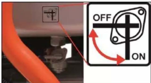
Fuel tap
text_image
OFF ON■ Set the fuel tap to the "ON" position.
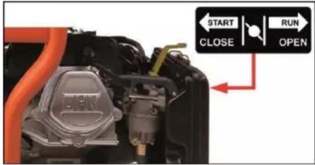
Choke
text_image
START CLOSE RUN OPENNOTE
Do not use the choke when the engine is warm.
■ Set choke to "RUN" position.
On/Off switch
text_image
FUKTEC RVR IC201 IC204 RVR FUKTEC RVR IC201 IC204 IC205 IC206 IC207 IC208 IC209 IC210 IC211 IC212 IC213 IC214 IC215 IC216 IC217 IC218 IC219 IC220 IC221 IC222 IC223 IC224 IC225 IC226 IC227 IC228 IC229 IC230 IC231 IC232 IC233 IC234 IC235 IC236 IC237 IC238 IC239 IC240 IC241 IC242 IC243 IC244 IC245 IC246 IC247 IC248 IC249 IC250 IC251 IC252 IC253 IC254 IC255 IC256 IC257 IC258 IC259 IC260 IC261 IC262 IC263 IC264 IC265 IC266 IC267 IC268 IC269 IC270 IC271 IC272 IC273 IC274 IC275 IC276 IC277 IC278 IC279 IC280 IC281 IC282 IC283 IC284 IC285 IC286 IC287 IC288 IC289 IC290 IC291 IC292 IC293 IC294 IC295 IC296 IC297 IC298 IC299 IC300■ Switch on/off switch to "I" - ON position.
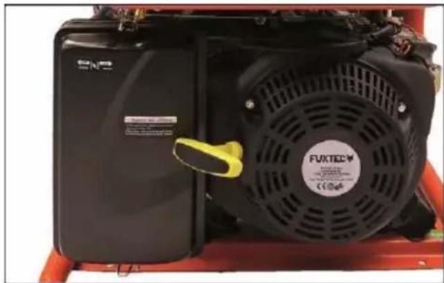
Starter handle (manual)
natural_image
Close-up of a black industrial fan with visible label and yellow clip, mounted on red equipment (no readable text or symbols)■ Pull out the yellow starter handle slowly until resistance is felt. Then pull forcefully.

CAUTION!
After a successful start, do not allow the pull rope to snap back. That risks injury and damage to components on the generator. Guide handle back slowly!
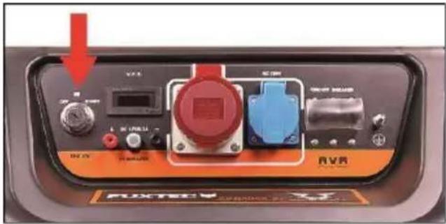
Key switch electric start
text_image
Control panel of a vehicle showing labeled buttons, indicators, and a red arrow pointing to a component.An electric starter is only available on the FX-SG7500B model.
■ Turn the key switch from the "ON" position to the "START" position.
■ After starting, turn the key switch back to the "ON" position.
After start
After starting the engine (or when the engine is already warm), turn the choke to the "START" position.
Commissioning
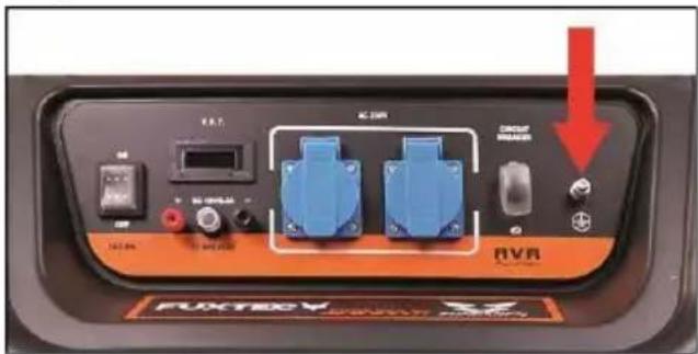
Before commissioning, the generator must be grounded.
text_image
IGBT KON CIRU RVR FXTEC MIXTEL SINEMA■ Connect the ground terminal of the generator to a metal frame or other suitable conductive metal structures.
■ Before commissioning, measure the protective grounding to detect and, if necessary, rectify faults in the protective grounding.

CAUTION!
Observe:
Inductive loads, such as electric motors, require a high starting current!
These include, e.g., fans, drilling machines, pumps (4-fold), wood splitters (4-fold), compressors, circular motors, etc.
compressors, circular saws, concrete cutters, and other construction equipment.
If the generator is to supply two or more loads, observe the following:
■ Connect and switch on loads one after the other.
■ Switch on high-power consumers with high current consumption or high starting recent first, then the lower-power consumers.
■ Never connect loads to the 230 V and 400 V sockets at the same time. In this case, the amplitude shift would immediately blow a fuse.
Connection

WARNING!
Never connect the generator to the mains supply on your own.

WARNING!
Qualified, authorized electricians may only carry out a cable connection to the house mains. Improper connection can cause fires and damage the generator!
Observe the following sequence:
■ Start engine (generator) - manually via cable pull with handle or electric starter.
■ Connect electrical consumers, observe the starting sequence.
■ Switch on AC fuse switch.
Switch off generator
Observe the following sequence:
■ Switch off AC fuse switch.
■ Switch the on/off switch of the generator to the "0" (OFF) position.
■ Turn the fuel tap to the "Shut off" position.

Maintenance and care

WARNING!
Before carrying out any maintenance, repair, cleaning, or inspection work, ensure that the engine is switched off and all components have cooled down. Unintentional starting is prevented by removing the spark plug connector from the engine.

WARNING!
In the interest of your safety, only perform the maintenance work described here yourself. In particular engine maintenance and repairs, all other work must be carried out by qualified, authorized personnel. Improperly performed work can lead to equipment damage and, as a consequence, to severe injuries.
Maintenance intervals
Before each start
■ Check engine oil level
■ Check air filter, visual inspection for dirt
After 20 h during initial operation
■ Change engine oil
After 20 h or every 3 months (every 10 h if dust is present)
■ Clean air filter
After 20 h or every 6 months
■ Change engine oil
■ Clean oil filter cup
■ Clean oil filter cup filter
■ Clean spark plug
After 20 h or every year
■ Check valve clearance, have adjusted if necessary
In case of emergency, immediately turn on/off switch of power directly to position "0" (OFF).
Maintenance measures
Engine oil change
NOTE
Drain the engine oil when the engine is still warm after shutdown. At this way, quick and complete draining of the engine oil is ensured.
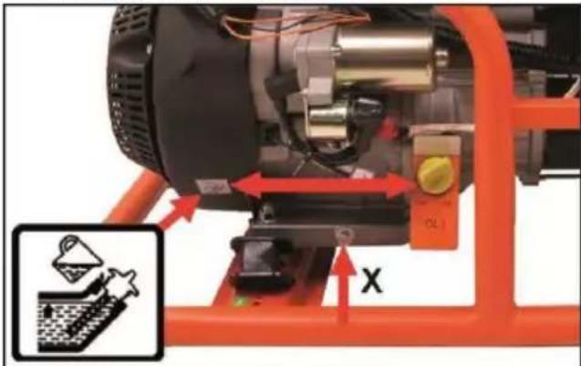
natural_image
Close-up of a mechanical device with orange frame and red directional arrows indicating motion, no visible text or symbols.■ Screw oil filler cap (yellow) with dipstick out of oil filler neck.
■ Position suitable drain container under the oil drain of the crankcase.
■ Unscrew drain plug (X) and drain crankcase completely.
■ Screw the drain plug firmly back into the crankcase.
■ Fill with engine oil of the specified quality up to the upper mark on the dipstick.
■ Screw the oil filler cap with dipstick firmly back into the oil filler neck.
Check spark plug
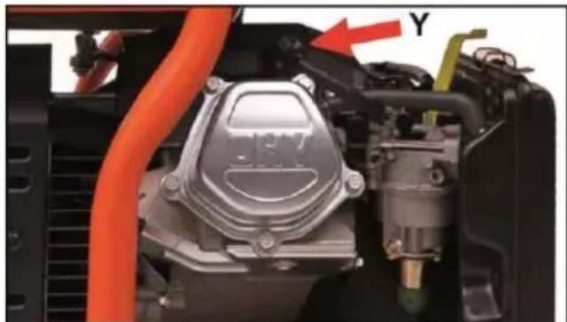
natural_image
Close-up of an automotive engine bay with orange hoses and a red arrow pointing to component Y (no visible text or symbols)☐ Remove spark plug cap (Y)
■ Unscrew the spark plug counterclockwise with the socket wrench.
■ Remove soot deposits from spark plug electrodes with a wire brush.
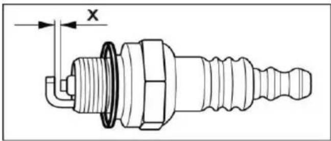
text_image
x■ Check electrode gap (X) with gauge, adjust to 0.7 to 0.8 mm if necessary.
■ Screw spark plug with gasket tightly into engine housing.
☐ Reassemble components in reverse order.
i NOTE!
A suitable spark plug wrench is included in the scope of delivery.
Cleaning the oil filter cup
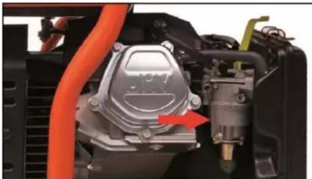
natural_image
Close-up of a mechanical engine component with orange tubing and a red arrow indicating a specific part (no visible text or symbols)NOTE!
The oil filter cup prevents dirt or water components from entering the carburettor.

text_image
OFF ON■ Close fuel shut-off valve in "OFF" position.
■ Unscrew the oil filter cup.
■ Blow out the oil filter cup thoroughly with compressed air against the direction of the arrow.
■ Place new rubber sealing ring on sealing surface of oil filter cup and screw oil filter cup back in.
Troubleshooting
The engine will not start.
- Check whether the on/off switch or the key switch (for generators with electric starter) is in the operating position - "ON" position.
■ Check the engine oil level. If the oil level is too low, the engine cannot be started.
■ Check if there is fuel in the fuel tank.
■ Disconnect the spark plug connector, remove the spark plug with the spark plug wrench and check its condition. - Use a wire brush to remove soot particles from the spark plug and electrodes.
- Check the electrode gap and adjust it to 0.7 to 0.8 mm if necessary.
The generator does not produce any current.
■ Connect a hand lamp to the generator to check.
- Check that the AC fuse switch is in the "ON" position.

CAUTION!
Observe:
If the generator still does not start 0 or does not generate power, contact your dealer or an authorized service shop for further troubleshooting.
Cleaning instructions

CAUTION!
Keep the power generator clean.
Neglecting cleaning measures may lead to material damage and malfunctions.
☐ Do not spray the power generator with water.
- Keep ventilation slots clean and free of dust.
■ Use a soft cloth and a soft brush for cleaning the exterior.
■ Clean the tank cover seals regularly and replace them if necessary.
Storage

NOTE!
Always store the power generator in a clean, dry, and frost-free place.
If the current collector is to be stored for a more extended period, proceed as follows:
■ Shut off fuel tap and unscrew oil filter cup counterclockwise, drain and blow out clean.
■ Position a suitable drain container under the drain, open the fuel tap, and drain the fuel entirely into the box.
■ Replace a sealing ring (rubber) and screw the oil filter cup back in clockwise.
■ Loosen carburettor drain plug and drain residual fuel from the carburettor into a suitable container. Tighten carburettor drain plug again.
■ Unscrew the oil filler cap, unscrew the oil drain plug and completely drain oil from the crankcase into a suitable container.
■ Retighten the oil drain plug and fill it with suitable engine oil up to the dipstick's upper mark. Screw the oil filler cap back into the oil filler neck. Pull until resistance is felt.
■ Pull the starter rope in doses until resistance is felt.
Transport

WARNING!
Danger of explosion!
When transporting the generator by car, always empty the fuel tank beforehand.

CAUTION!
Risk of injury!
Always switch off the power generator during transport and when changing location during work!
Repairs
Have repairs carried out exclusively by a customer service workshop authorized by the manufacturer with qualified and authorized personnel.
Disposal instructions

WARNING!
Make power generators to be scrapped unusable before disposal:
- Drain all operating fluids completely.
- Remove the spark plug and plug connector.

Recover raw materials instead of disposing of waste.
Recycle the generator, accessories, and packaging in an environmentally friendly manner.
Plastic parts are marked accordingly for recycling by type.

NOTE
Ask your specialist dealer or the local local authorities about suitable disposal options!
C€Conformity
We hereby declare that the product - FX SG series power generator - in its design and construction and in the version placed on the market by us complies with the basic safety and health requirements of the following directives (see 4. Applicable EC Directives).
This declaration refers only to the product in the condition in which it was placed on the market and excluded parts fitted and/or modifications carried out by the end-user.
- Description:
Gasoline-powered generator
- Type:
FX SG3800; FX SG7500; FX
SG7500A; FX SG7500B (KH3300,
KH7000, KH7003, KH7003E.
- Serial no:
On crankcase
- Applicable EC Directives:
2006/42/EC
- Additionally applied EC directives:
2006/42/EC; 97/68/EC; (EU) 2016/1628;
2000/14/EC; 2014/35/EU; 2014/30/EU
- Conformity assessment procedures:
2000/14/EC and 2005/88/EC
- Applied standards:
EN ISO 8528-13:2016
- Guaranteed sound
power level:
96 dB(A) for: FX SG3800
97 dB(A) for: FX SG7500 /
FX SG7500A /
FX SG7500B
Certification Body:
TÜV SÜD Product
Service GmbH,
Certification Body
Ridlerstrasse 65,
D-80339 Munich
- Responsible for technical documentation:
FUXTEC GmbH
Kappstrasse 69
D-71083 Herrenberg
Signature:
(Managing
Director) Date:
03.03.2021

Manufacturer:
FUXTEC GmbH
Kappstrasse 69
71083 Herrenberg – Germany
Contenuto
natural_image
Simple line drawing of a container pouring liquid into a tank (no text or symbols)text_image
13 14 15 21 20 19 18 17 16 Dynamical transducer 6-FM-14 m power RUMINING ELECTRIC BATTERY PDL Pb CE Electronic drive block Cable, 1.0 GB/GB Cable, 1.0 GB/GB Cable, 1.0 GB/GB Cable, 1.0 GB/GB Cable, 1.0 GB/GB Cable, 1.0 GB/GB Cable, 1.0 GB/GBnatural_image
Close-up of a mechanical device with orange frame and control panel, showing internal components and directional arrows (no text or symbols)
NOTA
natural_image
Close-up of a black FUXTEC air purifier with red arrows indicating flow direction (no text or symbols on the device itself)text_image
START CLOSE RUN OPENi NOTA
text_image
FUKTEC POWERED BY: FUKTECnatural_image
Close-up of a black industrial fan with visible label and yellow clip, mounted on red equipment (no readable text or symbols)text_image
V7.5 AC 100 DC 100 DC 100 DC 100 DC 100 DC 100 DC 100 DC 100 DC 100 DC 100 DC 100 DC 100 DC 100 DC 100 DC 100 DC 100 DC 100 DC 10 DC 10 DC 10 DC 10 DC 10 DC 10 DC 10 DC 10 DC 10 DC 10 DC 10 DC 10 DC 10 DC 10 DC 10 DC 10 DC 10 DC 10 DC 10 DC 10 DC 25 DC 25 DC 25 DC 25 DC 25 DC 25 DC 25 DC 25 DC 25 DC 25 DC 25 DC 25 DC 25 DC 25 DC 25 DC 25 DC 25 DC 25 DC 25 DC 25 DC 26 DC 26 DC 26 DC 26 DC 26 DC 26 DC 26 DC 26 DC 26 DC 26 DC 26 DC 26 DC 26 DC 26 DC 26 DC 26 DC 26 DC 26 DC 26 DC 26 DC 27 DC 27 DC 27 DC 27 DC 27 DC 27 DC 27 DC 27 DC 27 DC 27 DC 27 DC 27 DC 27 DC 27 DC 27 DC 27 DC 27 DC 27 DC 28 DC 28 DC 28 DC 28 DC 28 DC 28 DC 28 DC 28 DC 28 DC 28 DC 28 DC 28 DC 28 DC 28 DC 28 DC 28 DC 28 DC 28text_image
E.I.T. K-DR CIRCUIT RVR FUKTEC V RVR RVR RVR RVR RVR RVR RVR RVR RVR RVR RVR RVR RVR RVR RVR RVR RVR RVR RVR RVR RVR RVR RVR RVR RVR RVR RVR RVR RVR RVR RVR RVR RVR RVRnatural_image
Mechanical assembly diagram showing motor, valve, and piston components with directional arrows (no text or symbols)natural_image
Close-up of a mechanical engine component with orange hoses and a red arrow pointing to a yellow component (no visible text or symbols)natural_image
Close-up of a mechanical engine component with orange hoses and a red arrow indicating a specific part (no visible text or symbols)i NOTA!
2006/42/CE; 97/68/CE; (ÜE) 2016/1628;
2000/14/CE; 2014/35/UÊ; 2014/30/UÊ
natural_image
Close-up of a mechanical device with orange frame and red directional arrows indicating movement or force (no visible text or symbols)natural_image
Close-up of a black industrial fan with visible cooling fan and label, no readable text or symbolstext_image
Close-up of industrial machinery components with visible labels and red arrows indicating flow or movementtext_image
START CLOSE RUN OPENNOTE