FUR100 - Radio Soundmaster - Free user manual and instructions
Find the device manual for free FUR100 Soundmaster in PDF.
| Product type | Radio alarm clock with weather station and indoor/outdoor thermometer |
| Brand | Soundmaster |
| Model | FUR100 |
| Main power supply | AC adapter 100-240 V ~ 50/60 Hz, output 5.0 V ⎓ 2 A |
| Backup battery | Lithium CR2032 (not included) |
| Outdoor transmitter batteries | 2 AAA batteries (not included) |
| Indoor temperature range | 0 °C to +50 °C |
| Outdoor temperature range | -40 °C to +70 °C |
| FM radio range | 87.5 MHz - 108.0 MHz |
| FM preset memory | 10 stations |
| Display | LED with brightness dimmer (high/low/off) |
| Time functions | Radio-controlled DCF time, manual setting, 12/24 h, calendar |
| Alarms | 2 independent alarms with wake-up choice (buzzer or radio), adjustable snooze (5-60 min) |
| Sleep timer | 5, 15, 30, 45, 60, 75, 90 min or off |
| Weather station | Forecast based on atmospheric pressure (4 icons: sunny, partly cloudy, cloudy, rainy/snowy) |
| Wireless thermometer | Outdoor transmitter with range up to 50 m in open field, channel 1 |
| Dimensions (approximate) | Approx. 18 x 10 x 10 cm (estimate) |
| Weight (approximate) | Approx. 400 g without batteries (estimate) |
| Maintenance and cleaning | Clean with a dry cloth; do not use detergents or abrasive cloths |
| Safety | Do not open the device (risk of electric shock); do not expose to moisture, direct sunlight or heat sources; keep batteries away from children |
| Spare parts and repairability | No user-serviceable parts; reset button accessible at the rear; repair only by an authorized center |
| General information | Importer: Wörlein GmbH, Germany; compliant with directive 2014/53/EU |
Frequently Asked Questions - FUR100 Soundmaster
User questions about FUR100 Soundmaster
0 question about this device. Answer the ones you know or ask your own.
Ask a new question about this device
Download the instructions for your Radio in PDF format for free! Find your manual FUR100 - Soundmaster and take your electronic device back in hand. On this page are published all the documents necessary for the use of your device. FUR100 by Soundmaster.
USER MANUAL FUR100 Soundmaster
text_image
10:34 OUT 22°C 26°CDEUTSCH
ENGLISH
FRANÇAIS
NEDERLANDS
ITALIANO
ESPANOL
PORTUGUÊS
SVENSKA
ČEŠTINA
SLOVENSKÝ
LIETUVOS
Hersteller
natural_image
Line drawing of a device with a top base and internal components, showing no text or symbols.
natural_image
Technical line drawing of a door panel with an inset showing the internal structure (no text or symbols)Do not dispose of this product with the normal household waste at the end of its life cycle. Return it to a collection point for the recycling of electrical and electronic devices. This is indicated by the symbol on the product, user manual or packaging
The materials are reusable according to their markings. By reusing, recycling or other forms of utilization of old devices you make an important contribution to the protection of our environment.
Please contact your local authorities for details about collection points.
| WARNINGRisk of electric shockDo not open! |
Caution: To reduce the risk of electric shock, do not remove the cover (or back). There are no user serviceable parts inside. Refer servicing to qualified service personnel.

This symbol indicates the presence of dangerous voltage inside the enclosure, sufficient enough to cause electric shock.

This symbol indicates the presence of important operating and maintenance instructions for the device
Used batteries are hazardous waste and NOT to be disposed of with the household waste! As a consumer you are legally obligated to return all batteries for environmentally responsible recycling – no matter whether or not the batteries contain harmful substances*)
Return batteries free of charge to public collection points in your community or shops selling batteries of the respective kind. Only return fully discharged batteries ^* marked Cd = cadmium, Hg = mercury, Pb = lead
- Only use mercury and cadmium-free batteries.
- Used batteries are hazardous waste and NOT to be disposed of with the household waste!!!
- Keep batteries away from children. Children might swallow batteries.
- Contact a physician immediately if a battery was swallowed.
- Check your batteries regularly to avoid battery leakage.
- Batteries shall not be exposed to excessive heat such as sunshine, fire or the like.
- CAUTION: Danger of explosion if battery is incorrectly replaced
- Replace only with the same or equivalent type

WARNING
DO NOT INGEST BATTERY, CHEMICAL BURN HAZARD
This product contains a coin/button cell battery. If the coin/button cell battery is swallowed, it can cause severe internal burns in just 2 hours and can lead to death. Keep new and used batteries away from children. If the battery compartment does not close securely, stop using the product and keep it away from children.
If you think batteries might have been swallowed or placed inside any part of the body, seek immediate medical attention.
Safety, Environmental and Setup Instructions
- Use the device in dry indoor environments only.
- Protect the device from humidity.
- This apparatus is for moderate climates areas use, not suitable for use in tropical climates countries.
- No objects filled with liquids, such as vases, shall be placed on the apparatus.
- The mains plug or an appliance coupler is used as the disconnect device, the disconnect devices shall remain readily operable.
- Connect this device to a properly installed and earthed wall outlet only. Make sure the mains voltage corresponds with the specifications on the rating plate.
- Make sure the mains cable stays dry during operation. Do not pinch or damage the mains cable in any way.
- A damaged mains cable or plug must immediately be replaced by an authorized service center.
- In case of lightning, immediately disconnect the device from the mains supply.
- Children should be supervised by parents when using the device.
- Clean the device with a dry cloth only.
- Do NOT use CLEANING AGENTS or ABRASIVE CLOTHS!
- Do not expose the device to direct sunlight or other heat sources.
• Install the device at a location with sufficient ventilation in order to prevent heat accumulation.
- Do not cover the ventilation openings!
- Install the device at a safe and vibration-free location.
- Install the device as far away as possible from computers and microwave units; otherwise radio reception may be disturbed.
- Do not open or repair the enclosure. It is not safe to do so and will void your warranty. Repairs only by authorized service/ customer center.
- No naked flame sources, such as lighted candles, should be placed on the unit.
- When you are necessary to ship the unit store it in its original package. Save the package for this purpose.
- In case of malfunction due to electrostatic discharge or fast transient (burst), remove and reconnect the power supply.
- If the unit is not using for a long period of time, disconnect it from the power supply by unplugging the power plug. This is to avoid the risk of fire.
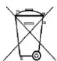
PRODUCT OVERVIEW
TOP VIEW
1 Down ▼/ WAVE
2 Volume
3 Radio / Sleep
4 Snooze / Dimmer zz•
5 Set / Memory
6 Alarm 1.2/ON.OFF
7 Up ▲
FRONT VIEW
8 Radio Controlled Signal
9 Time
10 Sleep
11 Memory
12 Alarm 1
13 Alarm 2
14 PM Indicator
15 Outdoor temperature
16 Indoor temperature
17 Weather Forecast Icon
BACK VIEW
18 Reset button
19 DC socket
20 Screw for battery door
21 Battery door
natural_image
Line drawing of a device with a vertical panel and a base component, showing no text or symbols.
natural_image
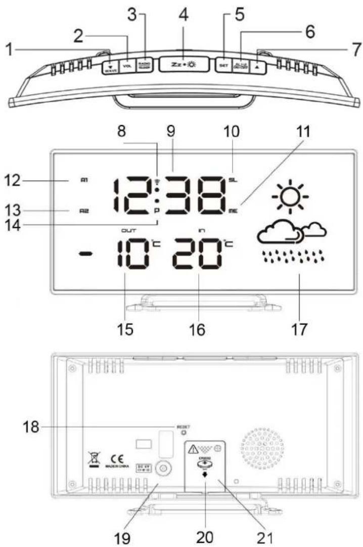
Technical line drawing of a rectangular device with ventilation slots and an internal component, showing a close-up view (no text or symbols)Wireless Outdoor Transmitter
- Keep in mind that your outdoor sensor has a 50 meter open-air transmission with no obstructions. Actual transmission range will vary depending on what is in the path of the signal. Each obstruction (roof, walls, floors, etc.) will effectively decrease the signal range.
- Insert the holder to the bottom of the outdoor transmitter for desktop or insert it to the back of the transmitter for wall mount purpose.
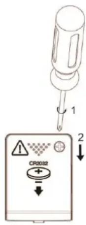
TO USE BACKUP BATTERY
Your clock radio requires one CR2032 lithium battery (not included) to provide backup power to the clock in the event of a temporary interruption.
- Place your unit face down on a flat and soft surface.
- Use a screw driver to open the backup battery compartment door on the back side of the unit.
- Slide and remove the battery cover at the bottom of your unit.
- Insert a new CR2032 lithium battery into the battery compartment with the “+” side facing up as indicated.
- Close the battery compartment door and tighten the battery door screw.
When the power supply is interrupted, the clock radio will be powered by the backup battery. The LED display is turned off, the alarm and the radio do not function.
text_image
1 CR0032 2CAUTION
Danger of explosion if the battery is incorrectly insert. Replace only with the same or equivantient type.
QUICK SETUP
1. INSTALL YOUR OUTDOOR TRANSMITTER
Keep your clock radio and wireless sensor next to each other. Slide back the battery cover at the back of your wireless outdoor transmitter. Make sure that the channel selector is set at position 1 (right position). Then insert 2x AAA batteries (not included) into the compartment. Install the batteries correctly by following the polarity (+ and -) indications in the battery compartment. Make sure that the switch is in position "1". Replace the battery door. Mount the Sensor weatherproof and do not expose it to direct sunlight.
Insert the DC jack to the back case of your clock radio. Then insert the AC/DC power adaptor into a standard AC wall outlet.
Your clock radio will receive data signal from the outdoor transmitter in few seconds. Then place your sensor in a dry and shaded area outdoor away from direct sun and rain. The temperature readings will become stable and more accurate after the unit is powered up for around 30 minutes.
3. SET THE FM ANTENNA
Extend the FM antenna fully and vary the direction for the best FM reception. Do not strip, alter or attach to other antennas.
4. RECEIVE RADIO CONTROLLED TIME
In around 3 minutes the clock radio will start to search for the DCF time signal. During the DCF reception, the LED display becomes dim and all buttons do not function. This normally takes around 7-10 minutes to complete the reception.
5. MANUALLY SET YOUR WEATHER ICONS
The weather stations computes weather forecast based on changes in air pressure. However, when using the weather station for the first time, it may take up to a few days of collecting sufficient information for more accurate forecasts. Manual setting of the weather forecast can slightly accelerate this process.
Please go to step 6 of "TO SET TIME, 12/24HR, CALENDAR, SNOOZE DURATION, WEATHER ICON".
ENVIRONMENTAL RECEPTION EFFECTS
Your radio controlled clock obtains the accurate time with wireless technology. Same as all wireless devices, the receiving ability may be affected by, but not limited to, the following circumstances:
- Long transmitting distance
• Nearby mountains and valleys - Among tall buildings
- Near railway, high voltage cable etc.
- Near freeway, airport, etc.
- Near construction site
• Inside concrete buildings
• Near electrical appliances
- Near computer and TV's
- Inside moving vehicles
• Near metallic structures
Place your clock at a location with optimal signal, i.e. close to a window and away from metal surface or electrical appliances.
CLOCK (DCF SIGNAL RECEPTION AND SIGNAL INDICATOR)
After your clock is powered up, it starts to receive DCF signal. The 📞icon flashes.
Receiving DCF signal icon flashing
Successful Reception icon becomes static
Failed Reception icon disappear
AUTOMATIC RECEPTION
Your clock starts automatic reception every day at 1:00, 2:00, and 3:00. If it fails to receive the DCF time signal at 3:00, it will start reception at 4:00. If it fails again, it will start reception at 5:00. If it fails again, it will start automatic reception at 1:00 again in the next day.
MANUAL RECEPTION
Simply press and hold the ▼ / WAVE button. Your clock will start manual reception. Press and hold the ▼ / WAVE button to stop DCF reception.
When your weather station is receiving the radio controlled time signal, the display will turn dimmer. It will resume to the brightness level which you originally selected after the radio controlled time reception is completed.
During RCC reception, all buttons do not function and it does not take temperature measurement.
Remark: turning on the FM radio during the DCF reception will affect the result of DCF time reception. It is recommended to temporarily turn off the FM radio (by one press the z when the clock radio is receiving the DCF time.
MANUAL SETTINGS
- Press and hold "SET", 00 flash, press ▼ / ▲ to set the time zone: -01 or 00 or 01.
"00" = GMT +1 hour (e.g. Germany)
"01" = GMT +2 hours (e.g. Finland)
"-01" = GMT 00 hour (e.g. U.K.)
-
Press "SET" again, hour digits flash. Press ▼ / ▲ to set hours. Press and hold ▼ / ▲ to accelerate setting at fast speed.
-
Press "SET" again, the minute digits flash. Press ▼ / ▲ to set minutes. Press and hold ▼ / ▲ to accelerate setting at fast speed.
-
Press "SET" again, the display shows "24Hr" flash. Press ▼ / ▲ to select 12Hr ⇔ 24Hr. In 12Hr mode, P (PM) will appear on the display to indicate afternoon time. There is no AM indicator.

soundmaster®
FUR100 / English Instruction Manual
-
Press "SET" again, display shows n5 and flash. Press ▼ / ▲ button to set snooze duration from n5 to n60 minutes.
-
Press "SET" once again, weather icons flash. Press ▼/ button to set the weather forecast condition according to the forecast on TV or internet.
-
Press SET once again to return to normal mode or it will return to normal mode in around 10 seconds if no further press of any other buttons.
| SUNNY |  |
| SUNNY AND CLOUDY(PARTLY SUNNY) |  |
| CLOUDY |  |
| RAIN/SNOW |  |
ALARM
SET ALARM
- Press and hold "AL 1.2/ON.OFF", the A1 LED and the hour digits flashes. Press ▼ / ▲ to set Alarm 1' hours. Press and hold ▼/ ▲ to accelerate your setting.
- Press "AL 1.2/ON.OFF" once again, the minutes digits flashes. Press ▼ / ▲ to set Alarm 1' minutes. Press and hold ▼/ ▲ to accelerate your setting.
- Press "AL 1.2/ON.OFF" once, the LED display shows "bu". To select the sound sources of your alarm press ▼/ bu = wake to buzzer rd = wake to radio
- Press "AL 1.2/ON.OFF" once. If "rd" (wake to radio) is selected, press ▼ / ▲ to select "HI" or "LO" for the volume of radio you wake up to. This section does not apply for "bu" (wake to buzzer).
- Press "AL1.2/ON.OFF" once the A2 LED and the hour digits flash. Press ▼ / ▲ to set Alarm 2'hour. Repeat step 2 to 5 above to set alarm 2.
- To store your alarm settings, press "SET" once (or if no button is pressed in around 10 seconds), your clock radio will return to normal time display mode.
When the related alarm is turned on, it will be indicated by the appearance of the A1 and / or the A2 LED on the left side of the display.
TURN ON / OFF ALARM 1 AND 2
- Press "AL 1.2/ON.OFF" once to activate Alarm 1, A1 LED appears.
- Press "AL 1.2/ON.OFF" once again to activate Alarm 2, A2 LED appears.
- Press once again to activate both Alarm 1 and 2. Both A1 and A2 LED's appear.
- Press once again to deactivate both alarms. Both A1 and A2 LED's disappear.
STOP AND RESET THE ALARM TO COME ON THE NEXT DAY
When alarm 1 or 2 is sounding, the related A1 or A2 LED flashes. Press the "RADIO / SLEEP" or "AL 1.2/ON.OFF" once to stop the alarm and reset it to come on the following day. After that A1 and / or A2 LED remains on the display.
SNOOZE OPERATION
When alarm is sounding, press zonde, the alarm will be silenced and come on again after the set snooze duration.
Note: If your second alarm activates while the first alarm is sounding or it is in the snooze mode, the second alarm overrides the first alarm (the first alarm is reset to come on the next day).
SLEEP TIMER
- When radio is turned on, press and hold "RADIO/SLEEP" to enter the sleep mode. The SL LED appear and the sleep time "05" (5 minutes) appear on the display.
- Press the "RADIO/SLEEP" again as needed to adjust the sleep timer from 5, 15, 30, 45, 60, 75, 90 or OFF.
- When the display changes back to show the time, press and hold "RADIO/SLEEP" to show the sleep time remaining.
- The radio will play for the programmed sleep time and then shut off.
- To turn off the radio before the sleep time has elapsed, press once.
DIMMER
Press z to select the LED brightness (high / low / off) of the LED display. This can only be done when the radio is off.
RADIO
- To turn on the radio, press "RADIO/SLEEP" once, the display shows "ON" and then the radio frequency readings in Mhz.
- Press ▲ or ▼ to tune the radio to a desired station. Press and hold ▼ / ▲ to scan for the next clear station.
- To adjust the volume, press "VOL" once, the display shows "L06", press ▼ / ▲ to adjust volume from L00 (sound off) to L15 (maximum).
- Press to turn off the radio.
Remark: Keep your radio away from fluorescent lamps or other electronic devices, which may cause interference to the radio.
PRESET MEMORY
The unit has 10 preset memories for FM.
- Turn on the radio and select a radio station you like to memorize.
- Press and hold the "SET" button until "ME" LED appears and "P01" flashes. Press "SET" once to store Memory 1.
- Press ▼ / ▲ to select another station you like to memorize. Then press and hold SET until "ME" LED appears and "P01" flashes. Press ▲ once, "P02" flashes. Press "SET" once to store Memory 02.
- Repeat step 2 to 3 to preset memories 3 through 10.
- To access a preset station at any time, press the "SET" one at a time while the radio is on.
- To edit a preset station, select another station and then repeat step 2 to 4. This overrides the original settings.
WEATHER STATION
There are four types of weather display in your clock radio:
| SUNNY | SUNNY AND CLOUDY | CLOUDY | RAIN/SNOW |
 |  |  |  |
The clock radio computes weather forecast based on changes in air pressure. However, when using it for the first time, it may take up to a few days of collecting sufficient information for more accurate forecast. Manual settings of the weather forecast can slightly accelerate this process.
Remarks: The weather icon indication is oriented from the changes of barometric pressure sensor in the clock radio. It takes few days to get stable.
If You Lose the Outdoor Temperature
- When the outdoor temperature digits show “--”, the wireless transmission is either interrupted or lost. Press & hold button of your clock radio to search for outdoor temperature signal (“--” flashes).
- If you continue to lose the outdoor temperature display, repeat 1) and then re-insert the batteries on the outdoor transmitter. Try placing the transmitter in a different location until you have smooth transmission of temperature data.
FACTORY RESET
In case your clock radio shows irrelevant information or digits, it can affected by electrostatic discharge or interferences from other devices. Press the "RESET" button on the back of your clock. Your clock radio will be reset to default setting of time and calendar and you need to set it up again.
TECHNICAL SPECIFICATIONS
| Power supply | : Use only the supplied power-adapter: |
| Power input | : 100-240V~ 50/60Hz 0,3A max. |
| Power output | : 5,0V +2A ⊖←⊕ |
| Temperature range indoor | : 0°C to +50°C (display shows LL.L/HH.H if out of this range) |
| Temperature range outdoor | : -40°C to +70°C (display shows LL.L/HH.H if out of this range) |
| Operation temperature | : 0°C to +45°C |
| FM range | : 87.5MHz – 108.0MHz |
IMPORTER
natural_image
Line drawing of a device with a vertical panel and a base component, no text or symbols present
natural_image
Technical line drawing of a vertical electronic device with a close-up inset showing internal components (no text or symbols)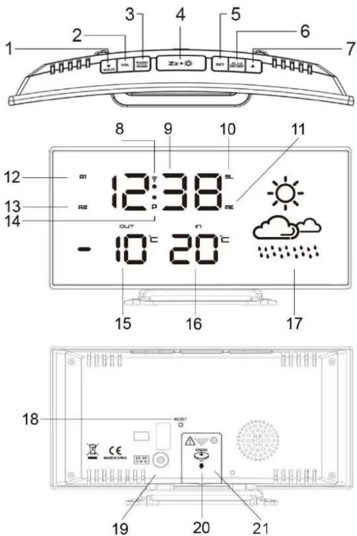
text_image
1 2 3 4 5 6 7 8 9 10 11 12 R1 12:38 SL R2 R3 ME OUT - 10°C 20°C 15 16 17 18 19 20 21natural_image
Line drawing of a device with a vertical panel and a base mount, showing no text or symbols.
natural_image
Technical line drawing of a door panel with an inset showing the internal structure (no text or symbols)2. VOER UW APPARAAT AAN
natural_image
Line drawing of a device with a vertical panel and a base component, no text or symbols present
natural_image
Technical line drawing of a rectangular electronic device with ventilation slots and an internal component (no text or symbols)2. ACCENSIONE DELL'UNITÀ
natural_image
Line drawing of a device with a vertical panel and a base mount, showing no text or symbols.
natural_image
Technical line drawing of a door panel with an inset showing the internal structure (no text or symbols)natural_image
Line drawing of a device with a vertical panel and a base component, no text or symbols present
natural_image
Technical line drawing of a vertical electronic device with a close-up inset showing internal components (no text or symbols)natural_image
Line drawing of a device with a vertical panel and a base component, no text or symbols present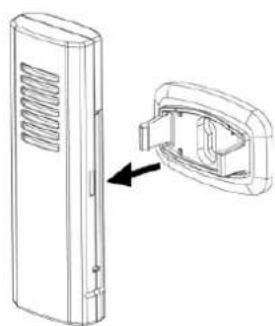
natural_image
Technical line drawing of a device with a close-up view showing internal components (no text or symbols)natural_image
Line drawing of a device with a ventilation grille and a base component, no text or symbols present
natural_image
Technical line drawing of a rectangular electronic device with ventilation slots and a close-up view showing internal components (no text or symbols)natural_image
Line drawing of a device with a vertical panel and a base component, no text or symbols present
natural_image
Technical line drawing of a rectangular device with ventilation slots and an internal component, showing a close-up view (no text or symbols)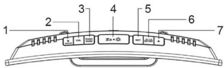
text_image
1 2 3 4 5 6 7 VIX SET ZZ+ SET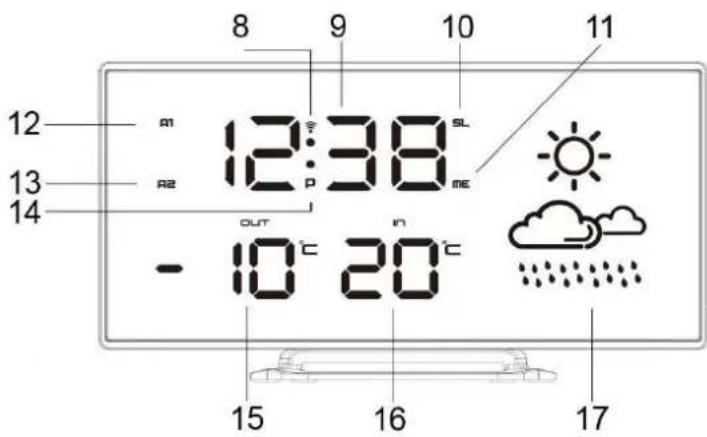
text_image
8 9 10 11 12 m 12:38 SL R2 me 13 14 OUT - 10°C 20°C 15 16 17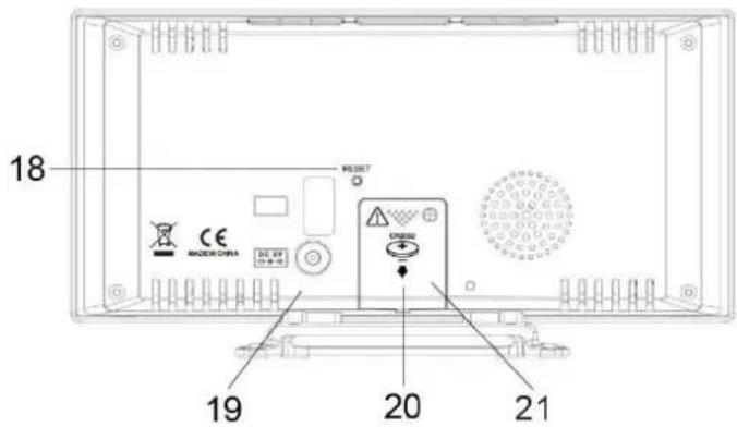
text_image
18 MODE 3 CHINA CE DO. 69 19 20 21VPLYVY PROSTREDIA NA PRÍJEM
natural_image
Line drawing of a device with a lid and ventilation grille, showing an upward arrow indicating assembly or change (no text or symbols present)
natural_image
Technical line drawing of a device with a side view showing internal components (no text or symbols)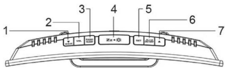
text_image
1 2 3 4 5 6 7 VCLK Zzz+0.02 SET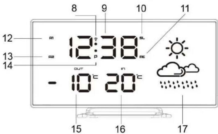
text_image
8 9 10 11 12 A1 12:38 SL A2 ME 13 OUT IN - 10°C 20°C 15 16 17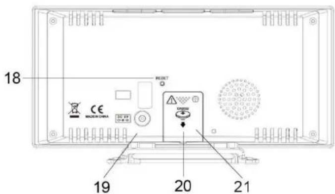
text_image
18 RESET CE MACSIN CHINA DC 69 20 21 19Hereby, Wörlein GmbH declares that this device is in compliance with the essenal requirements and other relevant provisions of Direcve 2014/53/EU.
A copy of the Declaraon of Conformity may be obtained at the following locaon:
Wörlein GmbH, Gewerbestrasse 12, D 90556 Cadolzburg, Germany
Email: info@woerlein.com
Tel.: +49 9103 71 67 0