WS 8011 - Clock TECHNOLINE - Free user manual and instructions
Find the device manual for free WS 8011 TECHNOLINE in PDF.
User questions about WS 8011 TECHNOLINE
0 question about this device. Answer the ones you know or ask your own.
Ask a new question about this device
Download the instructions for your Clock in PDF format for free! Find your manual WS 8011 - TECHNOLINE and take your electronic device back in hand. On this page are published all the documents necessary for the use of your device. WS 8011 by TECHNOLINE.
USER MANUAL WS 8011 TECHNOLINE
text_image
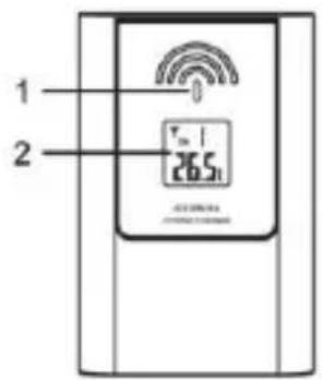
dudktübersicht 1 2 3 4 5 TEN TEN TEN TEN TEN TEN TEN TEN TEN TEN TEN TEN TEN TEN TEN TEN TEN TEN TEN TEN TEN TEN TEN TEN TEN TEN TEN TEN TEN TEN TEN TEN TEN TEN- [TIME SET] Taste
- [+CHANNEL] Taste
- [-/MEM] Taste
- [SNOOZE] Taste
- [ALARM SET] Taste
- Aufhängeöse
-
[°C/°F] Schiebeschalter
-
[SENSOR] Taste
- [RCC] Taste
- [RESET] Taste
- Tischaufstellung
- Batteriefach
Außensor
text_image
1 2 Vin 26.51 -45.000 Hz STRAW THI/MS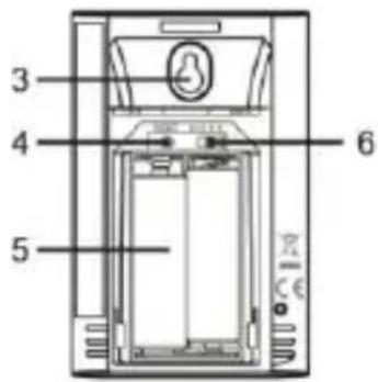
text_image
3 4 5 6DISPLAY Normal Modus

text_image
1 2 5 PM 10:00 13 12 59 11 42% - 1.0 °C 56% 25.5°C 8 7 4 6 3 10text_image
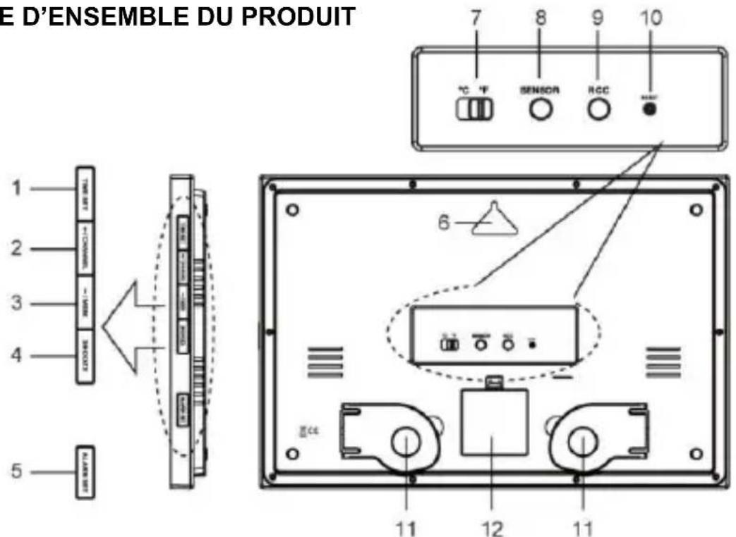
ODUCT OVERVIEW 1 2 3 4 5 TEN TEN TEN TEN TEN TEN TEN TEN TEN TEN TEN TEN TEN TEN TEN TEN TEN TEN TEN TEN TEN TEN TEN TEN TEN TEN TEN TEN TEN TEN TEN TEN TEN TEN- [TIME SET] button
- [+CHANNEL] button
- [-/MEM] button
- [SNOOZE] button
- [ALARM SET] button
- Wall-mounting hole
-
[^/^] slide switch
-
[SENSOR] button
- [RCC] button
- [RESET] button
- Table stand
- Battery door
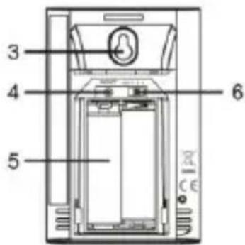
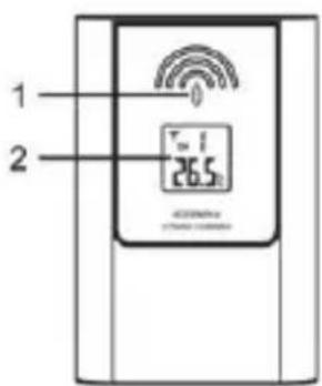
Remote sensor
- LED indicator
- LCD
- Wall mount hole
- [RESET] button
- Battery compartment
- [CHANNEL 1/2/3] slide switch
text_image
1 2 Tm 1 26.5 AC 0.000mA OFFICE 0.000mA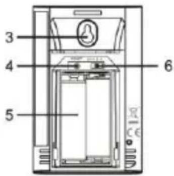
text_image
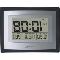
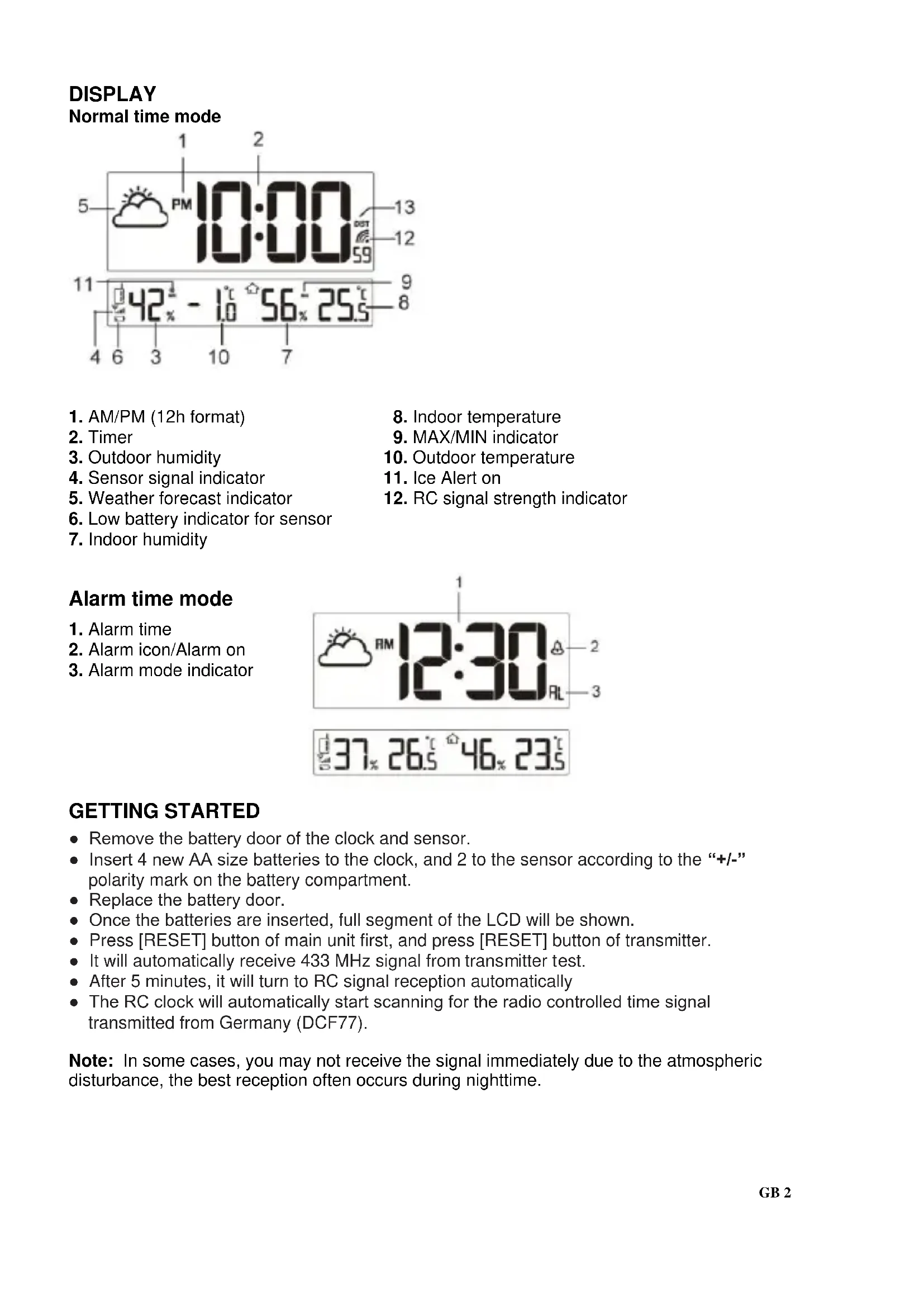
3 4 5 6DISPLAY Normal time mode
text_image
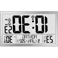
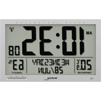
1 2 5 PM 10:00 13 12 59 11 42% - 1.0 °C 56% 25.5°C 8 7 4 6 3 10- AM/PM (12h format)
- Timer
- Outdoor humidity
- Sensor signal indicator
- Weather forecast indicator
- Low battery indicator for sensor
-
Indoor humidity
-
Indoor temperature
- MAX/MIN indicator
- Outdoor temperature
- Ice Alert on
- RC signal strength indicator
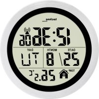
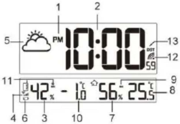
Alarm time mode
- Alarm time
- Alarm icon/Alarm on
- Alarm mode indicator
text_image
1 RM 12:30 A 2 RL 3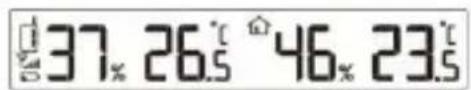
text_image
37% 26.5° 46% 23.5°GETTING STARTED
- Remove the battery door of the clock and sensor.
- Insert 4 new AA size batteries to the clock, and 2 to the sensor according to the “+/-” polarity mark on the battery compartment.
- Replace the battery door.
- Once the batteries are inserted, full segment of the LCD will be shown.
- Press [RESET] button of main unit first, and press [RESET] button of transmitter.
- It will automatically receive 433 MHz signal from transmitter test.
• After 5 minutes, it will turn to RC signal reception automatically - The RC clock will automatically start scanning for the radio controlled time signal transmitted from Germany (DCF77).
Note: In some cases, you may not receive the signal immediately due to the atmospheric disturbance, the best reception often occurs during nighttime.
HOW TO PAIR MAIN UNIT AND SENSOR
- Press [+/CHANNEL] button on main unit to select a channel.
- On sensor, slide channel switch to corresponding channel. (For additional sensors, select a different channel). Press [ RESET ] button.
- Press [SENSOR] on main unit to initiate search for 433 MHz reception.
433 MHz WIRELESS SENSOR RECEPTION
If the main unit receives wireless sensor signal successfully, the signal icon "Yall"
is displayed. If the main unit can not receive sensor signal or if signal is lost, the icon “ ” is displayed.
DAYLIGHT SAVING TIME (DST)
The clock will automatically advance the time by one hour in the spring and back an hour in the fall. Your clock will display "DST" during summer.
RECEPTION OF RADIO CONTROLLED SIGNAL
This clock includes a built-in receiver which picks up the signal from the DCF station. Therefore, the clock automatically sets the time, date and weekday.
- The clock automatically carries out four periodic synchronization procedures (at 2:00 AM, 8:00 AM, 2:00 PM and 8:00 PM daily) with the RC signal to correct any deviations to the exact time.
- Once the unit synchronizes successfully to the RC signal, the signal icon “☐” will show up. Each synchronization process will take between 6 to 16 minutes.
- To manually start the signal reception, press [RCC] button once or press and hold it for 3 seconds in order to stop the reception.
Note: • The strength of radio-controlled time signal from the transmitter tower may be affected by geographical location or building around.
- Always place the unit away from interfering sources such as TV set, computer, etc.
- Avoid placing the unit on or next to metal plates.
- Closed areas such as airport, basement, tower block, or factory are not recommended.
SIGNAL RECEPTION INDICATOR
The signal indicator displays signal strength in 4 levels. Wave segment flashing means time signals are being received. The signal quality could be classified into 4 types:
- RC synchronize process
6 Weak signal quality
Acceptable signal quality
Excellent signal quality
SETTING THE TIME
- In normal time mode, press and hold [TIME SET] button for 3 seconds until the 12/24 Hr flashes.
- Press [+/CHANNEL] / [-/MEM] button to set 12/24 Hour format.
- Press [TIME SET] button again until Hour digit flashes and press [+ / CHANNEL] / [- / MEM] button to adjust its value.
- Repeat above operations to set the time in this sequence:
12/24Hr>Hour>Minute>Second>+/-23 Time zone
- Press [TIME SET] button to save the setting and return to normal time mode. Or the clock will automatically exit the setting mode after 1 minute without pressing any button.
Note: • When setting second, press [+ / CHANNEL] / [- / MEM] button to set its value to 00.
SETTING THE ALARM TIME
- In normal time mode, press [ ALARM SET ] button to enter alarm time mode.
Press and hold [ ALARM SET ] for 3 seconds until Hour digit flashes.
- Press [ +/-CHANNEL ] / [ -/MEM ] button to set its value.
- Press [ ALARM SET ] button again to step to Minute setting.
Press [ +/CHANNEL ] / [ -/MEM ] button to set its value.
- Press [ ALARM SET ] button to save the setting and return to normal time mode. Or the clock will automatically exit the setting mode after 1 minute without pressing any button.
Note: After pressing [ +/CHANNEL ] / [ -/MEM ] button, alarm function is automatically turned on (icon " 🔊" displayed).
USING THE ALARM AND SNOOZE
- In normal time mode, press [ ALARM SET ] button to enter alarm time mode.
Press [ ALARM SET ] button again to turn on (icon “ ⚙ ” displayed) or turn off alarm function.
If alarm is turned on, alarm beeps at the alarm time.
Alarm beeping can be stopped by:
- Auto stop if no button is pressed during alarm sound beeping. Alarm beeping lasts for 2 minutes.
- Press [ SNOOZE ] button to stop the current alarm and enter snooze. Alarm icon will be flashing continuously. The alarm will sound again in 5 minutes.
Snooze can be operated continuously in 24 hours.
- Press [ ALARM SET ] button to turn off alarm function.
TEMPERATURE AND HUMIDITY DISPLAY
Slide [°C/°F] switch on main unit to <°C> or <°F>.
To read outdoor temperature and humidity
The default displayed channel is channel 1.
-
In normal mode, press [+/CHANNEL] button repeatedly to view readings of channel 1, 2 and 3.
-
Press and hold [+/CHANNEL] button for 2 seconds to enter channel auto-change, and channels change automatically in every 4 seconds.
-
Press [+/CHANNEL] again to return to normal mode.
Note: 1. Once the channel is assigned to one sensor, you can only change it by removing the batteries or resetting the unit.
-
If no signals are received or the transmission is interfered, “---” will appear on the LCD.
-
Relocate the main unit and sensor in other positions and make sure the transmission is within the effective range of 30 meters approx.
-
Try out where your multifunctional main unit receives the signals best.
VIEWING MAXIMUM AND MINIMUM RECORDS
- Press [-/MEM] button to review maximum and minimum indoor & outdoor temperature and humidity records.
- While reviewing the maximum and minimum records, press and hold [-/ MEM] button for 3 seconds to clear both max & min records.
Note: 1. Record value will be updated by new higher or low record.
- Once you re-insert batteries to the main unit, all of the value will be defaulted.
WEATHER FORECAST
This main unit contains built-in sensitive pressure sensor to predict weather forecast in next 12 to 24 hours.

Sunny

Slightly cloudy

Cloudy

Rainy
Note: 1. The accuracy of a general pressure-based weather forecast is about 70% to 75%.
2. The weather forecast is meant for the next 12 \~ 24 hours, it may not necessarily reflect the current situation.
ICE ALERT
When the outdoor temperature falls between -2°C to 3°C (28°F to 37°F), the ice alert icon will display on the LCD and flash continuously, and disappear once the temperature is out of this range.
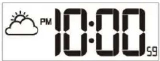
text_image
PM 10:00 59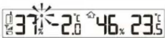
text_image
37% -2.0 46.% 23.5BATTERY REPLACEMENT
When the LCD becomes dim, replace with 4 AA size batteries at once; while if the low battery indicator “☐” displays in the outdoor window, replace with 2 AA size batteries to the sensor at once.
Note: • If the clock is not used for a long time, please take off the batteries.
SPECIFICATIONS
Radio controlled signal: DCF77
RF transmission frequency: 433MHz
RF transmission range: Maximum 50 meters
No. of remote sensor: Up to 3 units
Temperature sensing cycle: Around 60\~64 seconds
Indoor temperature
Display range: -40^ +70^ ( -40^ 158^ )
Operating range: 0^ +45^ ( 32^ 113^ )
Accuracy -20°C \~ 0°C +/- 2°C (+/- 4.0°F)
$$ 0 ^ {\circ} \mathrm{C} \sim 4 0 ^ {\circ} \mathrm{C} + / - 1 ^ {\circ} \mathrm{C} (+ / - 2. 0 ^ {\circ} \mathrm{F}) $$
$$ 4 0 ^ {\circ} \mathrm{C} \sim 6 0 ^ {\circ} \mathrm{C} + / - 2 ^ {\circ} \mathrm{C} (+ / - 4. 0 ^ {\circ} \mathrm{F}) $$
Indoor humidity
Display range: 1% \~ 99%
Operating range: 20% \~ 90%
Resolution: 1%
Accuracy: 20% \~ 39% +/- 8% RH @ 25°C
40% \~ 70% +/- 5% RH @ 25°C
71% \~ 90% +/- 8% RH @ 25°C
Outdoor temperature
Display range: -40^ +70^ ( -40^ 158^ )
Operating range: -20^ +60^ (-4^ 140^)
Accuracy -20°C \~ 0°C +/- 2°C (+/- 4.0°F)
0^ C 40^ C + / - 1^ C (+ / - 2.0^ F)
40^ 60^ + / - 2^(+ / - 4.0^)
Outdoor humidity
Display range: 1% \~ 99%
Operating range: 20% \~ 90%
Resolution: 1%
Accuracy: 20% \~ 39% +/- 8% RH @ 25°C
40% \~ 70% +/- 5% RH @ 25°C
71% \~ 90% +/- 8% RH @ 25°C
Power
Main unit: 4 x AA size 1.5V batteries
Remote sensor: 2 x AA size 1.5V batteries
Dimension
Main unit: 430 x 288 x 33 mm
Remote sensor: 65 x 100 x 35 mm
Precautions
• This main unit is intended to be used only indoors.
• Do not subject the unit to excessive force or shock.
• Do not expose the unit to extreme temperatures, direct sunlight, dust or humidity.
• Do not immerse in water.
- Avoid contact with any corrosive materials.
• Do not dispose this unit in a fire as it may explode.
• Do not open the inner back case or tamper with any components of this unit.
Batteries safety warnings
• Use only button cell batteries, not rechargeable batteries.
• Install batteries correctly by matching the polarities (+/-).
• Always replace a complete set of batteries.
• Never mix used and new batteries.
- Remove exhausted batteries immediately.
- Remove batteries when not in use.
• Do not recharge and do not dispose of batteries in fire as the batteries may explode.
• Ensure batteries are stored away from metal objects as contact may cause a short circuit.
- Avoid exposing batteries to extreme temperature or humidity or direct sunlight.
- Keep all batteries out of reach from children. They are a choking hazard.
Consideration of duty according to the battery law
Old batteries do not belong to domestic waste because they could cause damages of health and environment. You can return used batteries free of charge to your dealer and collection points. As end-user you are committed by law to bring back needed batteries to distributors and other collecting points!
Consideration of duty according to the law of electrical devices

This symbol means that you must dispose of electrical devices separated from the General household waste when it reaches the end of its useful life. Take your unit to your local waste collection point or recycling centre. This applies to all countries of the European Union, and to other European countries with a separate waste collection system.
VUE D'ENSEMBLE DU PRODUIT
text_image
E D'ENSEMBLE DU PRODUIT 1 2 3 4 5 6 7 8 9 10 °C °F SENSOR RCC CE 11 12 11- [TIME SET] Touche
- [+CHANNEL] Touche
- [-/MEM] Touche
- [SNOOZE] Touche
- [ALARM SET] Touche
- Orifice pour la fixation murale
-
[°C/°F] Commutateur
-
[SENSOR] Touche
- [RCC] Touche
- [RESET] Touche
- Socle
- Couvercle du compartiment des piles
Capteur distant
text_image
37.26°46.23MISE EN ROUTE
text_image
37°-2.0°46.23.5REMPLACEMENT DES PILES
text_image
37% 26.5° 46% 23.5°GETTING STARTED
- Remove the battery door of the clock and sensor.
- Insert 4 new AA size batteries to the clock, and 2 to the sensor according to the “+/-” polarity mark on the battery compartment.
- Replace the battery door.
- Once the batteries are inserted, full segment of the LCD will be shown.
- Press [RESET] button of main unit first, and press [RESET] button of transmitter.
- It will automatically receive 433 MHz signal from transmitter test.
• After 5 minutes, it will turn to RC signal reception automatically - The RC clock will automatically start scanning for the radio controlled time signal transmitted from Germany (DCF77).
Note: In some cases, you may not receive the signal immediately due to the atmospheric disturbance, the best reception often occurs during nighttime.
CÓMO EMPAREJAR LA UNIDAD PRINCIPAL Y EL SENSOR
text_image
ODUCT OVERVIEW 1 2 3 4 5 TEN TEN TEN TEN TEN TEN TEN TEN TEN TEN TEN TEN TEN TEN TEN TEN TEN TEN TEN TEN TEN TEN TEN TEN TEN TEN TEN TEN TEN TEN TEN TEN TEN TEN- [TIME SET] -toets
- [+CHANNEL] -toets
- [-/MEM] -toets
- [SNOOZE] -toets
- [ALARM SET] -toets
- Ophangoogje
-
[°C/°F] -schuifschakelaar
-
[SENSOR] -toets
- [RCC] -toets
- [RESET] -toets
- Tafelsteun
- Batterijklepje
Afstandsensor
- LED-indicator
- LCD
- Ophangoog
- [RESET]-toets
- Batterijhouder
- [CHANNEL 1/2/3]-schuifschakelaar
text_image
1 2 0 T=1 26.5°C 42300mA STRAW 1200MHz