ED1500KDIG - Metal lathe Holzmann - Free user manual and instructions
Find the device manual for free ED1500KDIG Holzmann in PDF.

| Product type | Metal lathe |
| Brand | Holzmann |
| Model | ED1500KDIG |
| Dimensions (L x W x H) | Approx. 1840 x 780 x 450 mm |
| Weight | Approx. 800 kg |
| Power supply | 400 V three-phase, 50 Hz |
| Number of spindle speeds | 12 speeds (45 to 2000 rpm) |
| Metric thread | 0.8 to 14.0 mm (36 steps) |
| Inch thread | 2 to 28 TPI (30 steps) |
| Longitudinal feed | 0.02 to 0.85 mm/rev |
| Cross feed | 0.005 to 0.22 mm/rev |
| Max turning diameter over bed | 400 mm |
| Distance between centers | 1500 mm |
| Included chuck | Self-centering 3-jaw chuck |
| Included accessories | Independent 4-jaw chuck, tool post, fixed and traveling steady rests, tailstock, tool holder, coolant pump |
| Safety devices | Emergency stop, chuck guard with interlock, headstock cover, spiral spring on leadscrew, overload coupler |
| Maintenance | Oil change of headstock, feed gearbox and carriage apron every 1000 h or annually |
| Work light | Integrated service indicator lamp |
| Supplied with | Complete user manual of 215 pages |
Frequently Asked Questions - ED1500KDIG Holzmann
User questions about ED1500KDIG Holzmann
0 question about this device. Answer the ones you know or ask your own.
Ask a new question about this device
Download the instructions for your Metal lathe in PDF format for free! Find your manual ED1500KDIG - Holzmann and take your electronic device back in hand. On this page are published all the documents necessary for the use of your device. ED1500KDIG by Holzmann.
USER MANUAL ED1500KDIG Holzmann
natural_image
Industrial machine with red and gray components, no visible text or symbols on main bodyCE
ED1000KDIG
ED1500KDIG

YOUR
JOB.
OUR
TOOLS.
1 INHALT / INDEX / SOMMAIRE
1 INHALT / INDEX / SOMMAIRE 2
2 SICHERHEITSZEICHEN / SAFETY SIGNS / SYMBOLES DE SÉCURITÉ / SINAIS DE SEGURANÇA / BEZPEČNOSTNÍ ZNAČKY....10
3 TECHNIK/TECHNIC/TECHNIQUE/TECNOLOGIA/TECHNICKÁ ČÁST......12
3.1 Lieferumfang / Delivery content / Contenu de la livraison / Volume de fornecimento / Rozsah dodávky 12
3.2 Komponenten / Components / Composants / Componentes / Komponenty 13
3.21 Digitale Positionsanzeige (3-Achsen) / digital read out unit (3-axis) / Affichage numérique de la position (3 axes) / Indicador digital de posição (3 eixos) / Digitální indikace polohy (3 osy).....14
322 Bedienelemente / Control elements / Éléments de commande / Elementos de controlo / Ovládací prvky....16
3.3 Technische Daten / Technical Data / Données techniques / Dados técnicos / Technické údaje....17
4 VORWORT (DE) 20
5 SICHERHEIT 21
15.1 Intended use of the machine....56
15.1.1 Technical restrictions....56
15.1.2 Prohibited applications / Hazardous misapplications 56
15.2 User requirements....56
15.3 Safety devices....57
15.4 General safety instructions....57
15.5 Electrical safety....58
15.6 Special safety instructions for lathes....58
15.7 Hazard warnings....58
16 TRANSPORT 59
17 ASSEMBLY....60
17.1 Preparatory activities....60
17.12 Cleaning and lubrication....60
17.13 Site requirements 60
17.1.4 Anchorless assembly 61
17.1.5 Anchored assembly....61
17.1.6 Assembling....62
17.2 Machine settings....63
17.2.1 Aligning / leveling the lathe 63
17.22 Checking the fit of the jaw chuck 63
17.23 Mounting workpiece holders....64
17.24 Adjusting the headstock....65
17.2.5 Adjusting the tailstock 65
17.2.6 Adjusting the sliding guides....66
17.2.7 Visual inspection....66
17.2.8 Filling with coolant....67
17.29 Function test....67
17.3 Electrical connection....67
18 OPERATION....68
18.1 Operations preparation ....68
18.2 Retracting the machine 68
18.2.1 Performing a test run....69
18.3 Operating the machine 69
18.3.1 Control icons....69
18.3.2 Switching on the machine....70
18.3.3 Intermittent push button....71
18.3.4 Foot brake....71
18.4 Setting spindle speed and rotation direction 71
18.4.1 Spindle speed selection....71
18.4.2 Direction of rotation....72
18.4.3 Running operation....72
18.5 Threads and feeds 72
18.5.1 Change gear gearbox....72
18.5.2 Manual feed 73
18.5.3 Automatic feeds....73
18.5.4 Cutting threads 74
18.5.5 Thread pitch table / longitudinal feed for metric threads....74
18.5.6 Thread pitch table / longitudinal feed for imperial threads....74
18.5.7 Thread dial indicator (for resumption of the pitch) 75
18.6 Tool post....76
18.7 Mounting steady or follow rests....76
18.8 Tailstock....77
18.8.1 Tailstock laterally offset....77
18.9 Gap....77
18.10 General working instructions....78
18.10.1 3-jaw chuck....78
18.10.2 4-jaw chuck....79
18.10.3 Face plate 79
18.10.4 Longitudinal turning....79
18.10.5 Plain turning and recessing....80
18.10.6 Fixing the lathe slide 80
18.10.7 Turning between tips....80
18.10.8 Turning short taper with the top slide....80
18.10.9 Thread cutting....81
19 CLEANING 81
20 MAINTENANCE 81
20.1 Inspection and maintenance plan 82
20.1.1 Adjusting the taper gibs....82
20.12 Visual inspection of oil levels 83
20.1.3 Oil change headstock, feed gear and apron 83
20.1.4 Other lubrication points 84
20.1.5 Checking and cleaning the coolant system....84
20.1.6 Replacing the V-belt 85
20.1.7 Replacing jaws 85
20.1.8 Adjusting the overload clutch on the feed spindle....86
21 STORAGE....86
22 DISPOSAL 86
23 TROUBLESHOOTING....87
24 AVANT-PROPOS (FR) 88
25 SÉCURITÉ....89
40.1.1 Reajustar as barras trapezoidais 152
40.17 Mudar as mandíbulas....154
60 DÉCLARATION DE GARANTIE (FR)......213
61 GARANTIA (PT) 214
62 PROHLÁŠENÍ O ZÁRUCE (CZ)......215
READ THE MANUAL! Read the user and maintenance manual carefully and get familiar with the controls in order to use the machine correctly and to avoid injuries and machine defects.
EN Never wear gloves when working on rotating parts!
EN Switch off the machine before repairing, servicing or stopping work and pull out the mains plug
natural_image
Four blue circular icons representing different safety and equipment symbols: walking, boots, helmet, and headphones (no text or labels)EN Wear personal protective equipment!
EN Warning of rotating parts
EN Warning of hand injuries
EN Warning of pointed (sharp) tool
EN Warning of danger of slipping
EN Missing or non-readable safety stickers have to be replaced immediately!
text_image
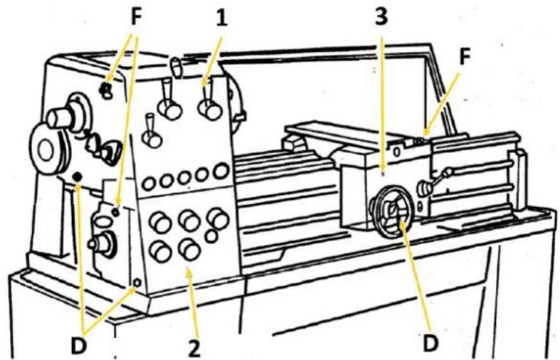
Exploded view diagram of a lathe machine with numbered parts and assembly instructionsED1000KDIG (ED1000K)
| 1 | Metalldrehmaschine / metal turning lathe / Tour à métal / Torno para metal / Soustruh na kovy | 11 | Reduzierhülse MK6-MK4 / reducing sleeve MT6-MT4 / Manchon de réduction MK6-MK4 / Manga redutora MK6-MK4 / Redukční pouzdro MK6-MK4 |
| 2 | Digitale Positionsanzeige / digital read out unit / Affichage numérique de la position / Indicação digital da posição / Digitální ukazatel polohy | 12 | Ölkanne (Symbolbild) / oil gun (symbol pic) / Burette à huile (image de symbole) / Almotolia (imagem simbólica) / Olejnička (symbolický obrázek) |
| 3 | Wechsel-Zahnrad Satz (Z: 54, 56, 57,2x 60, 63, 66, 78)/ change gears (T: 54, 56, 57,2x 60, 63, 66, 78) / Jeu de changement de roue d'engrenage (Z : 54, 56, 57,2x 60, 63, 66, 78) / Jogo de rodas dentadas (Z: 54, 56, 57,2x 60, 63, 66, 78) / Sada výměnných ozubených kol (Z: 54, 56, 57,2x 60, 63, 66, 78) | 13 | Körnerspitzen, 2 Stk. / centering, 2 pcs. / Contrepointes, 2 pcs / Pontas de grão, 2 unid. / Upínací hroty, 2 ks |
| 4 | Schlüssel E-Verteiler/ key connecting box / Clé du tableau de distribution électrique / Chave do distribuidor elétrico / Klíč elektrické rozvodné skříňky | 14 | Spannbacken-Set für 3-Backenfutter / set of reverse jaws for 3-jaw chuck / Jeu de mors de serrage pour mandrin à 3 mors / Conjunto de mordentes para mandril de 3 mandíbulas / Sada upínacích čelistí pro tříčelistové sklíčidlo |
| 5 | 4-Backenfutter ∅ 200 mm / 4-jaw chuck, ∅ 200 mm / 4 mandrins de mors ∅ 200 mm / Mandril de 4 mandíbulas ∅ 200 mm / Tříčelistové sklíčidlo ∅ 200 mm | 15 | Backenfutter-Spannschlüssel / key for jaw chuck / Clé de serrage de mandrin de mors / Chave de fixação das mandíbulas / Upínací klíč na čelistová sklíčidla |
| 6 | Inbusschlüssel-Satz /hex key set / Jeu de clefs Allen / Jogo de chaves de Allen / Sada inbusových klíčů | 16 | Camlock-Spannschlüssel / key for camlock / Clé de serrage Camlock / Chave de fixação Camlock / Upínací klíč typu Camlock |
| 7 | Werkzeugbox (Symbolfoto) / tool box (symbol pic) / Boîte à outils (photo d'illustration) / Caixa de ferramentas (foto simbólica) / Skříňka s nářadím (ilustrační foto) | 17 | Werkzeughalterschlüssel / tool post key / Clé de porte-outils / Chave do porta-ferramentas / Klíč na držák nástroje |
| 8 | Kreuzschlitz.-Schraubendreher / cross point screwdriver / Tournevis cruciforme / Chave de fendas Phillips / Krížový šroubovák | 18 | Planscheibe ∅ 320 mm / face plate, ∅ 320 mm / Plateau porte-outils ∅ 320 mm / Mesa horizontal ∅ 320 mm / Lícní deska ∅ 320 mm |
| 9 | Gabelschlüssel-Set / set of open end wrenches / Jeu de clés à fourche / Jogo de chave de boca / Sada otevřených klíčů | 19 | Handradgriffe / levers for handwheels / Poignées de volant / Manípulos do volante / Rukojeti ručního kolečka |
| 10 | Flachkopfschraubendreher / flat head screwdriver / Tournevis à tête plate / Chave de fendas de cabeça chata / Plochý šroubovák | 20 | Betriebsanleitung / user manual / Mode d'emploi / Manual de instruções / Návod k použití |
text_image
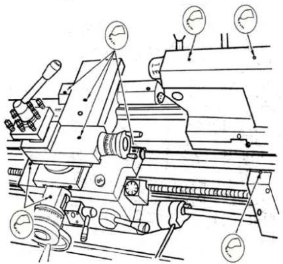
Labeled diagram of a lathe machine with numbered components for identificationED1000KDIG (ED1000K)
| 1 | Spindelstock / headstock / Poupée fixe / Cabeçote / Vřeteník | 16 | Zugspindel / feed rod / Broche de chariotage / Fuso de tração / Tažný hřídel |
| 2 | Digitale Positionsanzeige / digital readout unit / Affichage numérique de la position / Indicador digital de posição / Digitální ukazatel polohy | 17 | Schaltspindel / control spindle / Broche de commutation / Fuso de comando / Řadicí vřeteno |
| 3 | Drehfutterschutz / chuck guard / Protection du mandrin du tour / Proteção do mandril do torno / Ochranný prvek soustružnického sklíčidla | 18 | Handrad Oberschlitten / handwheel top slide / Volant du chariot à mouvements croisés / Volante do deslizador superior / Ruční kolo horních saní |
| 4 | Spindel mit 3-Backenfutter / spindle with 3-jaw chuck / Broche à mandrins à | 19 | Schalthebel Drehrichtung / shift lever rotating direction / Levier de commutation du sens de rotation / Alavanca de |
natural_image
Industrial machine with control panel and yellow circular annotations (no readable text or symbols)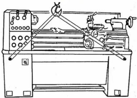
natural_image
Technical line drawing of a lathe machine with levers and control panel (no text or labels)natural_image
Close-up of a mechanical assembly with a red circle highlighting a component (no visible text or symbols)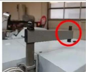
natural_image
Industrial machine component with a red circle highlighting a small mechanical part (no visible text or symbols)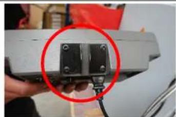
natural_image
Close-up of a hand holding a small electronic component with a red circle highlighting it, no visible text or symbols.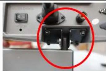
natural_image
Close-up of a mechanical component with a red circle highlighting a detail (no visible text or symbols)
natural_image
Close-up of a network switch with multiple Ethernet connectors and labeled ports (X, Y, Z), no readable text beyond labels.Montage DRO
natural_image
Industrial machinery setup with a metal frame and a red circle highlighting a component (no visible text or symbols)natural_image
Technical line drawing of a mechanical device with a red circle highlighting a component (no text or symbols present)natural_image
Close-up of a circular mechanical component with red curved arrows indicating rotation or force direction (no text or symbols)natural_image
Close-up of a circular mechanical component with a central square and a red circle highlighting a feature, placed on a metallic surface (no text or symbols visible)natural_image
Close-up of a metallic mechanical component with a central hole and red measurement lines (no text or symbols visible)natural_image
Close-up of a metallic mechanical component with a conical tip, possibly a cutting tool or machine (no visible text or symbols)text_image
J 1 A 6 inch 150mm B PIN K Jnatural_image
Technical line drawing of a mechanical assembly with no visible text or symbolsStellschrauben
natural_image
Close-up of a mechanical component with a highlighted circular feature (labeled '1') and no visible text or symbols.natural_image
Close-up of a mechanical device with a red circle highlighting a component, no visible text or symbolsnatural_image
Close-up of a wall corner with four red-circled mounting holes (no text or symbols visible)natural_image
Exterior view of a red and yellow cable or wire component with labeled part '1' (no text or symbols beyond label)natural_image
Close-up of a mechanical component with a red knob and yellow arrow pointing to it, no visible text or symbols.text_image
Labeled mechanical assembly diagram showing components 1, 2, and 3 with directional arrows and numbered partstext_image
A B C D E F G H Inatural_image
Close-up of a mechanical component with a red arrow indicating direction, no visible text or symbolstext_image
Technical diagram of a mechanical assembly with labeled parts and directional arrows indicating motion or movement.natural_image
Two abstract mechanical or architectural diagrams showing cross-sections of structural components (no text or symbols)natural_image
Two abstract geometric diagrams with shaded regions, no text or symbols presentnatural_image
Abstract geometric diagram with concentric circles and radial segments, no text or symbols presentnatural_image
Close-up of a mechanical assembly with red arrows pointing to specific components (no visible text or symbols)natural_image
Close-up of a mechanical component with a highlighted circular feature and arrow indicator (no readable text or symbols)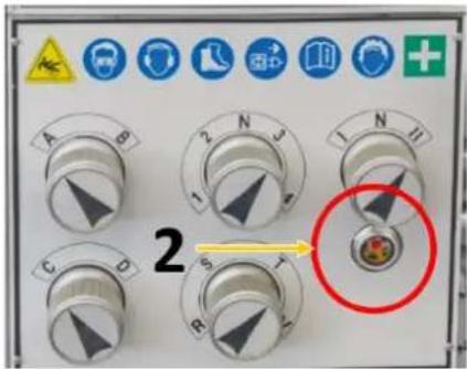
text_image
2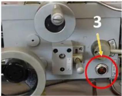
natural_image
Close-up of a mechanical device with labeled component '3' and a red circle highlighting a specific part (no readable text or symbols beyond the number)natural_image
Technical line drawing of a lathe machine with gauges and levers (no text or labels)natural_image
Mechanical assembly diagram showing a metal bracket with red circular features and two views of internal components (no text or symbols)text_image
Technical diagram showing two steps of a mechanical assembly with labeled components, including red circles highlighting features.This operating manual contains information and important notes for safe start-up and handling of the metal lathe ED1000KDIG, ED1500DKIG, hereinafter referred to as "machine".

The manual is an integral part of the machine and must not be removed. Keep it for later use in a suitable place, easily accessible to users (operators), protected from dust and moisture, and enclose it with the machine if the machine is passed on to third parties!
Please pay special attention to the chapter Safety!
Due to the constant further development of our products, illustrations and contents may differ slightly. If you notice any errors, please inform us.
Technical changes reserved!
Check the goods immediately after receipt and make a note of any complaints on the consignment note when the delivery person takes them over!
Transport damage must be reported separately to us within 24 hours.
Holzmann Maschinen GmbH cannot accept any liability for transport damage not noted.
Copyright
© 2023
This document is protected by international copyright law. Any unauthorized duplication, translation or use of pictures, illustrations or text of this manual will be pursued by law.
Court of jurisdiction is the Landesgericht Linz or the competent court for 4170 Haslach, Austria!
Customer service contact
This section contains information and important notes on safe start-up and handling of the machine.

For your own safety, read these operating instructions carefully before putting the machine into operation. This will enable you to handle the machine safely and prevent misunderstandings as well as personal injury and damage to property. In addition, observe the symbols and pictograms used on the machine as well as the safety and hazard information!
15.1 Intended use of the machine
The machinery is intended exclusively for the following operations: longitudinal and face turning of round or regularly shaped 3-, 6- or 12-sided workpieces of plastic, metal or similar materials which are not hazardous to health, flammable or explosive, each within the prescribed technical limits.
HOLZMANN MASCHINEN GMBH assumes no responsibility or warranty for any other use or use beyond this and for any resulting damage to property or injury.
15.1.1 Technical restrictions
The machine is intended for use under the following ambient conditions:
| Rel. Humidity: | max. 70 % |
| Temperature (Operation) | +5°C to +40°C |
| Temperature (Storage, Transport) | -20°C to +50°C |
15.1.2 Prohibited applications / Hazardous misapplications
- Operating the machine without adequate physical and mental aptitude
- Operating the machine without knowledge of the operating instructions
- Changes in the design of the machine
- Use of emery cloth by hand
- Operating the machine outdoors
- Processing of dust generating materials such as wood, magnesium, carbon, etc. (fire and explosion hazard!)
- Operating the machine in a potentially explosive environment (machine can generate ignition sparks during operation)
- Operating the machine outside the technical limits specified in this manual
- Remove the safety markings attached to the machine.
- Modify, circumvent or disable the safety devices of the machine.
The improper use or disregard of the versions and instructions described in this manual will result in the voiding of all warranty and compensation claims against Holzmann Maschinen GmbH.
15.2 User requirements
The machine is designed for operation by one person. The physical and mental aptitude as well as knowledge and understanding of the operating instructions are prerequisites for operating the machine. Persons who, because of their physical, sensory or mental abilities or their inexperience or ignorance, are unable to operate the machinery safely must not use it without supervision or instruction from a responsible person.
Basic knowledge of metalworking especially the correlation of material, tool, feed and speeds.
Please note that local laws and regulations may determine the minimum age of the operator and restrict the use of this machine!
Put on your personal protective equipment before working on the machine.
Work on electrical components or equipment may only be carried out by a qualified electrician or under the instruction and supervision of a qualified electrician.
15.3 Safety devices
The machine is equipped with the following safety devices:
 | A self-locking Emergency Stop button on the headstock to stop dangerous movements at any time. |
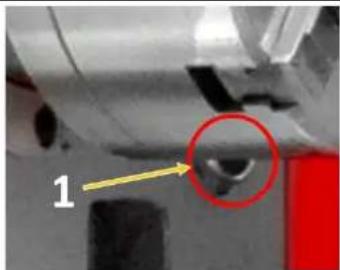
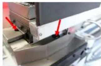
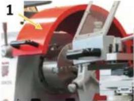 | A jaw chuck guard (1) with position switch. The machine only switches on when the jaw chuck guard is closed. |
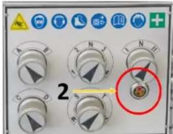
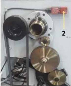 | A protective cover on the headstock with position switch (2). The machine only switches on when the protective cover is fitted. |
 | A spiral spring as a protective cover on the leadscrew (prevents clothing from being drawn in) |
 | An overload clutch on the feed spindle |
15.4 General safety instructions
To avoid malfunctions, damage and health hazards when working with the machine, the following points must be observed in addition to the general rules for safe working:
- Before start-up, check the machine for completeness and function. Only use the machine if the guards and other non-parting guards required for machining have been fitted, are in good operating condition and have been properly maintained.
- Choose a level, vibration-free, non-slip surface for the installation location.
- Ensure sufficient space around the machine!
- Ensure sufficient lighting conditions at the workplace to avoid stroboscopic effects.
- Ensure a clean working environment.
• Only use perfect tools that are free of cracks and other defects (e.g. deformations).
- Remove tool keys and other adjustment tools before switching on the machine.
- Keep the area around the machine free of obstacles (e.g. dust, chips, cut parts, etc.).
- Check the strength of the machine connections before each use.
- Never leave the running machine unattended. Switch off the machine before leaving the working area and secure it against unintentional or unauthorised recommissioning.
- The machine may only be operated, serviced or repaired by persons who are familiar with it and who have been informed of the hazards arising from this work.
- Ensure that unauthorised persons maintain a safe distance from the machine and keep children away from the machine.
- When working on the machine, never wear loose jewellery, loose clothing, ties or long, open hair.
- Hide long hair under hair protection.
- Wear close-fitting protective clothing and suitable protective equipment (eye protection, dust mask, ear protection; gloves only when handling tools).
- Metal dust can contain chemical substances that can have a negative effect on health. Work on the machine should only be carried out in well-ventilated rooms. If necessary, use a suitable extraction system.
- If there are connections for dust extraction, make sure that they are properly connected and in working order.
• Always work with care and the necessary caution and never use excessive force.
- Do not overload the machine!
- Shut down the machine and disconnect it from the power supply before carrying out any adjustment, conversion, cleaning, maintenance or repair work. Before starting any work on the machine, wait until all tools or machine parts have come to a complete standstill and secure the machine against unintentional restarting.
- Do not work on the machine if it is tired, not concentrated or under the influence of medication, alcohol or drugs!
- Do not use the machine in areas where vapours from paints, solvents or flammable liquids represent a potential danger (danger of fire or explosion!).
15.5 Electrical safety
• Make sure that the machine is earthed.
• Only use suitable extension cords.
• Proper plugs and sockets reduce the risk of electric shock.
- The machine may only be used if the power source is protected by a residual current circuit breaker.
• Before connecting the machine turn the main switch to position "0".
15.6 Special safety instructions for lathes
- Clamp the workpiece firmly before turning on the lathe.
- Clamp the lathe tool to the correct height and as short as possible.
- Do not wear gloves when turning!
- Keep sufficient distance from all rotating parts.
- Switch off the lathe before measuring the workpiece.
- Remove the clamping key from the chuck after each tool change.
• Never remove any chips by hand! Use a chip hook, rubber wiper, hand brush or brush.
- When using cooling lubricants, observe the manufacturer's instructions and use a skin protection agent if necessary.
15.7 Hazard warnings
Despite intended use, certain residual risks remain when operating the machine.
- Formation of a flow chip
- This wraps around the forearm and causes severe cuts.
- Throwing away workpieces or tools at high speed.
- Always check workpieces for suitability and clamp them securely and firmly
- Clamp and center longer workpieces via an additional counter bearing (e.g. tailstock)
- For very long workpieces, use a steady rest
• Risk of electric shock if incorrect electrical connections are used.
- Risk of tripping due to supply lines on the floor.
- Properly route supply lines and cables
- Mark unavoidable tripping hazards yellow-black
Residual risks can be minimized if the "Safety instructions" and the "Intended use" as well as the operating instructions are observed. Due to the design and construction of the machine, hazardous situations may occur which are identified as follows in these operating instructions:
DANGER

A safety instruction designed in this way indicates an imminently hazardous situation which, if not avoided, will result in death or serious injury.
WARNING

Such a safety instruction indicates a potentially hazardous situation which, if not avoided, may result in serious injury or even death.
CAUTION

A safety instruction designed in this way indicates a potentially hazardous situation which, if not avoided, may result in minor or moderate injury.
NOTICE

A safety notice designed in this way indicates a potentially hazardous situation which, if not avoided, may result in property damage.
Irrespective of all safety regulations, your common sense and appropriate technical suitability/training are and will remain the most important safety factor for error-free operation of the machine. Safe working primarily depends on you!
16 TRANSPORT
WARNING

Damaged or insufficiently strong hoists and load slings can result in serious injury or even death. Before use, therefore, check hoists and load slings for adequate load-bearing capacity and perfect condition. Secure the loads carefully. Never stand under suspended loads!
To ensure proper transport, observe the instructions and information on the transport packaging regarding centre of gravity, attachment points, weight, means of transport to be used and the prescribed transport position, etc.
Transport the machine in its packaging to the place of installation. To manoeuvre the machine in the packaging, a pallet truck or forklift truck with the appropriate lifting force can be used, for example. Ensure that the selected lifting equipment (crane, forklift, pallet truck, load sling, etc.) is in perfect condition. Lifting and transporting the machine may only be carried out by qualified personnel with appropriate training for the lifting equipment used.
NOTICE

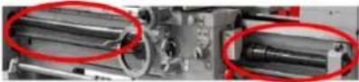
Avoid using sling chains as there is a risk of damaging the feed screw or the lead screw. Make sure that the lead screw, feed screw and selector shaft of the lathe are not touched by the lifting slings when lifting. Never lift the machine by the spindle!
To position the machine at the installation location, proceed as follows:
natural_image
Industrial machine with control panel and yellow indicator lights, no visible text or symbols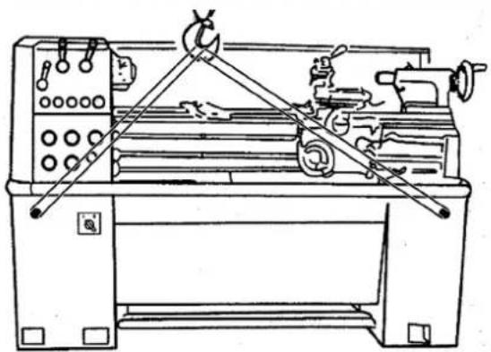
natural_image
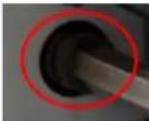
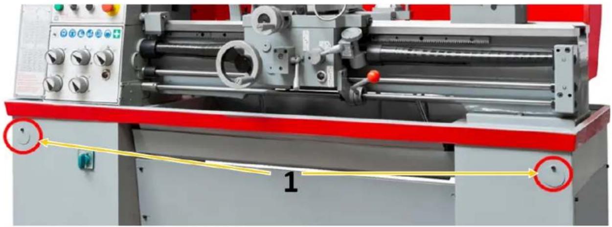
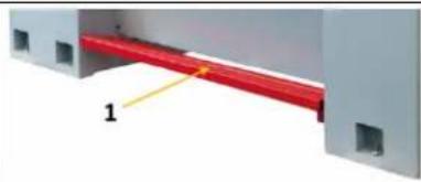
Technical line drawing of a lathe machine with levers and control panel (no text or labels)- Prepare two sufficiently strong round steel bars (length approx. 800 mm, ∅ approx. 35 mm).
- Guide the round steel bars through the prepared holes (1) in the stand.
- Attach a lifting sling to each of the four ends of the two round steel bars.
- Lift the machine with a suitable conveyor (e.g. crane).
Note: Before lifting, check that the tailstock is clamped. Ensure that the load stop is balanced. If necessary, change the position of the bed carriage and/or tailstock to obtain a balanced load stop.
17 ASSEMBLY
17.1 Preparatory activities
17.1.1 Checking delivery content
Always note visible transport damage on the delivery note and check the machine immediately after unpacking for transport damage or missing or damaged parts. Report any damage to the machine or missing parts immediately to your retailer or freight forwarder.
17.1.2 Cleaning and lubrication
Before you install and commission the machine at the intended location, carefully remove the anti-corrosion protection and grease residues.
Under no circumstances should you use nitro thinner or other cleaning agents that could attack the machine's paint.
Oil bare machine parts (e.g. machine bed, tailstock sleeve, feed spindle) with an acid-free lubricating oil.
17.1.3 Site requirements
Place the machine on a solid surface. A concrete floor is the best foundation for the machine. If necessary, use an underframe.
The space required by the machine and the required load-bearing capacity of the subfloor result from the technical data (dimensions, weight) of your machine. When designing the working area around the machine, observe the local safety regulations. When dimensioning the required space,
take into account that the operation, maintenance and repair of the machine must be possible without restrictions at all times.
The selected installation location must ensure a suitable connection to the electrical mains.
17.1.4 Anchorless assembly
NOTICE

The use of machine feet (not supplied) facilitates levelling of the machine and reduces vibrations.
After the machine has been brought into the desired position at the intended installation location, it must be levelled in the longitudinal and transverse axes using the pressure screws.
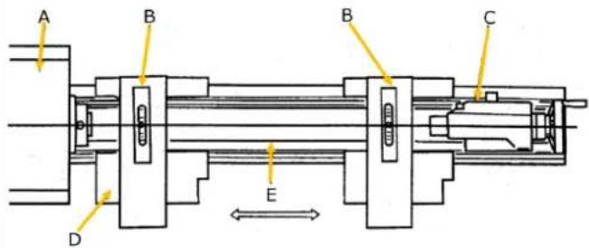
text_image
A B B C D EA ... Head Stock;
B... Precision Balance;
C ... tailstock;
D ... saddle & cross slide
E ... bed slideway
text_image
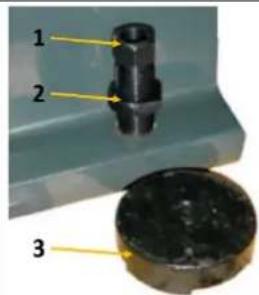
1 2 317.1.5 Anchored assembly
NOTICE

Insufficient rigidity of the substrate leads to the superposition of vibrations between the machine and the substrate (natural frequency of components). If the stiffness of the overall system is insufficient, critical speeds are reached quickly, which leads to poor turning results.
Use the anchored assembly to achieve a rigid connection with the ground. This reduces the vibration potential. The anchored assembly is always useful when turning knives or turning tools with HM alloy are to be used and/or large parts up to the maximum capacity of the machine are to be machined.
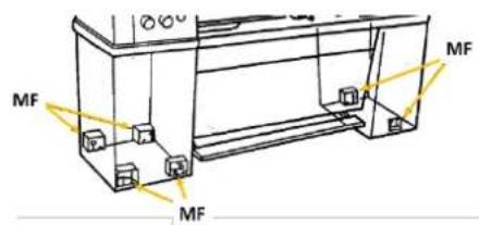
text_image
MF MF MF- Place the machine on the anchor bolts (MF) adjusting disks (3).
- Then align the machine and tighten the screws (1).
- Check the alignment of the machine again after having tightened the counter nuts (2).
- Repeat levelling procedure if necessary.
text_image
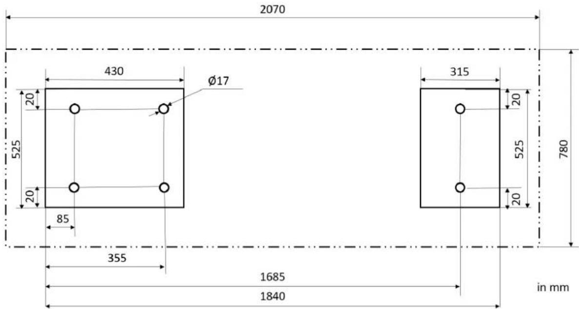
2070 430 Ø17 525 20 20 85 355 1685 1840 315 20 525 20 780 in mm17.1.6 Assembling
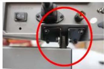
The machine is pre-assembled, the parts removed for transport must be assembled according to the following instructions and the connection to mains have to be made.
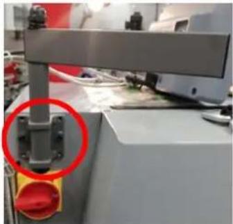 | Mounting the DROMount the bracket for the digital position indicator (DRO) above the main switch with the 2 screws. |
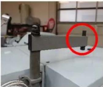 | Fasten the bracket on the cross support. |
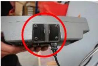 | Fasten the 2 brackets to the DRO with 4 Allen screws and 4 washer. |
natural_image
Close-up of a mechanical device with a red circle highlighting a component (no visible text or symbols)
natural_image
Close-up of a network switch with metallic connectors and labeled ports X, Y, Z (no additional text or symbols visible)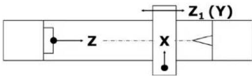
text_image
Z X Z₁(Y)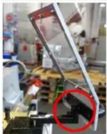
natural_image
Laboratory setup with mechanical components and a red circle highlighting a specific part (no visible text or symbols)Mounting the tool post guard
Place the tool post guard on the bracket and fix it with the Allen screw.
17.2 Machine settings
17.2.1 Aligning / leveling the lathe
After installation and commissioning, it is recommended to check the alignment and levelling of the machine before using it for the first time. In order to ensure working accuracy, the alignment and levelling should be repeated at regular intervals.
natural_image
Technical line drawing of a mechanical device with a highlighted section (no text or symbols)To level the machine, use a precision spirit level (according to DIN 877) with an accuracy of 0.02 mm to 1000 mm. This allows the horizontal position of the machine axis to be checked with sufficient accuracy in both the longitudinal and transverse directions.
For anchored installation: Do not tighten the anchor bolt nuts carefully and evenly until three to four days after the cement has cured.
Repeat the horizontal check a few days after initial start-up and every six months thereafter.
17.2.2 Checking the fit of the jaw chuck
NOTICE

Do not use cast iron chucks. Use ductile iron chucks only. Before disassembling the jaw chuck, place a stable board or chuck cradle under the spindle to protect the precision-ground surfaces.
NOTICE

When mounting a chuck or face plate, first make sure that the cam-lock studs are properly fixed. Otherwise, the chuck/face plate may never be removed again later because the cam-lock studs have become twisted.
natural_image
Close-up of a circular mechanical component with red curved arrows indicating rotation or movement (no text or symbols)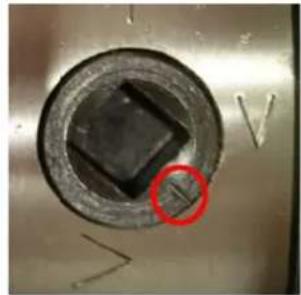
natural_image
Close-up of a circular mechanical component with a black square hole and a red circle highlighting a feature, no visible text or symbols.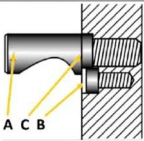
text_image
A C B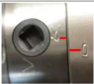
natural_image
Close-up of a metallic mechanical component with a circular hole and red indicator lights (no text or symbols visible)Carefully disassemble the jaw chuck. To do this, loosen the cam-locks by turning them clockwise (approx. one third of a turn) using the clamping key supplied and carefully remove the jaw chuck.
Check the cam-lock studs. Ensure that they are not damaged or broken during transport. Clean all parts thoroughly. Also clean the spindle and the cam-locks. Lightly oil the spindle, cam-locks, camlock studs and chuck body with a suitable machine oil.
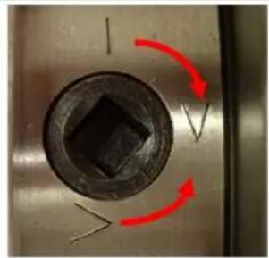
Then lift the jaw chuck up to the spindle nose and press on the spindle. Tighten the cam-lock studs by turning the cam-locks counterclockwise. After tightening, the cam-lock line should be located between the two V-marks - see illustration on the left. If a cam is not within this mark, remove the chuck or face plate and adjust the height of the cam-lock studs - see the following illustration.
The cam-lock stud is correctly adjusted when the mark (C) carved into the stud is flush with the back of the chuck.
If the cam-lock line is outside the V markings, adjust the height of the relevant cam-lock stud.
To do this, first loosen the retaining screw (B), adjust the cam-lock stud by turning it in/out one full turn at a time and then tighten the retaining screw firmly again.
If the chuck (clamping device) is correctly fastened, a reference mark should be attached to the spindle and clamping device so that the clamping device can always be released and remounted in the same position to ensure optimum concentricity.
Do not change chucks or face plates between lathes without checking for correct cam-locking.
17.2.3 Mounting workpiece holders
WARNING

The max. spindlespeed of the machine must be lower than the max. permissible speed of the used workpiece holder.
Centring tip
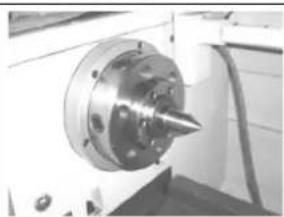
natural_image
Close-up of a mechanical tool with a conical tip mounted on a flanged circular base (no visible text or symbols)- Clean the inner taper of the spindle holder.
- Clean the morse taper and the taper of the centering tip.
- Press the centring tip with the morse taper into the inner taper of the turning spindle holder.
Face plate
- Check the fitting surfaces on the turning spindle holder and on the workpiece carrier to be mounted for cleanliness and undamaged holding surfaces.
- Check that all clamping bolts in the spindle holder are in the open position.
- Lift the face plate onto the turning spindle holder.
- Fasten the clamping bolts as described in the section "Checking the fit of the jaw chuck".
4-jaw chuck
NOTICE

The shoulder for centering the four-jaw chuck on the mounting flange was not finished for reasons of concentricity. The mounting flange must be adapted to the 4-jaw chuck.
- Check the fitting surfaces on the turning spindle mounting and on the flange to be mounted for the four-jaw chuck for cleanliness and undamaged mounting surfaces.
- Check that all the clamping bolts in the spindle holder are in the open position.
- Lift the flange onto the spindle holder.
- Fasten the clamping bolts as described in the section "Checking the fit of the jaw chuck".
Adjust the centering shoulder on the locating flange to the four-jaw chuck in axial and radial run-out by turning.
17.2.4 Adjusting the headstock
The headstock (1) was aligned at the factory. If, contrary to expectations, an adjustment is required, proceed as follows:
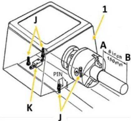
text_image
J 1 A 6 inch 150mm B PIN K JClamp one end of a steel tube 150 mm long and 50 mm in diameter into the headstock chuck. The other end runs free. Now remove a thin layer with a sharp turning chisel. The values measured with the dial gauge or calliper at points A and B must match. If this is not the case, loosen the four headstock fixing screws (J) to correct the difference (two are below the headstock) and readjust using the adjusting screw (K). Then tighten the fixing screws again and repeat the rotation, measurement and adjustment until the measured values match and the machine runs smoothly.
17.2.5 Adjusting the tailstock
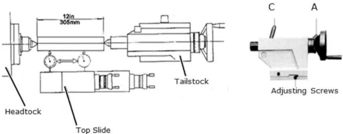
text_image
12in 305mm Headstock Top Slide Tailstock C A Adjusting ScrewsA ... clamping lever tailstock; C ... clamping lever spindle sleeve;
To adjust the tailstock, clamp a ground steel tube 305 mm long between the headstock and tailstock tips (see illustration above). Now place a dial gauge on the top slide and pull it along the workpiece axis below the workpiece.
If the dial gauge shows different values, loosen the tailstock clamping lever (A) and readjust using the two set screws. Repeat this procedure until both points are exactly aligned.
17.2.6 Adjusting the sliding guides
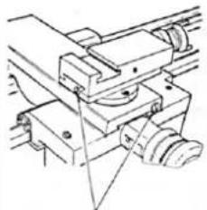
natural_image
Technical line drawing of a mechanical assembly with no visible text or symbolsAdjusting Screws
The sliding guides of the cross slide and top slide are equipped with bevelled guide rail adjusting screws (see illustration on the left), which can be used to eliminate any play that may occur there over time.
Ensure that the slideways are thoroughly cleaned before adjustment. Then adjust the guide pads by loosening the rear guide pad adjusting screw a little while tightening the front one a little. Ensure that smooth running is guaranteed over the entire sliding guide section. Too tight an adjustment will result in increased wear and heavy, jerky running.
17.2.7 Visual inspection
NOTICE

The machine is delivered with running-in oil! This oil must be changed after the running-in period (approx. 100 operating hours). Failure to do so may cause serious damage to the machine. For running operation, use a viscous oil with viscosity ISO 220 (e.g. GOE5L) or a comparable SAE140 oil!
NOTICE


Lubricants are toxic and must not be released into the environment! Always follow the manufacturer's instructions and, if necessary, contact your local authority for information on proper disposal.
Check the lubrication of the following parts and top up with suitable oil if necessary before working on the machine:
Headstock
natural_image
Close-up of a mechanical component with a highlighted circular feature (labeled '1') and an arrow pointing to it, no readable text or symbols present.The bearing of the headstock is in an oil bath. Make sure that the oil level always reaches the mark of the sight glass (1). Check the oil level regularly.
First oil change after 100 operating hours, then change the oil once a year or after 1000 operating hours.
See Maintenance
Feed gear
text_image
2Make sure that the oil level always reaches the mark of the sight glass (2).
First oil change after 100 operating hours, then change the oil once a year or after 1000 operating hours.
See Maintenance
Apron

natural_image
Close-up of a mechanical device with labeled component '3' and a red circle highlighting a specific part (no readable text or symbols)Check the oil level regularly using the oil sight glass (3) on the front.
First oil change after 100 operating hours, then change the oil once a year or after 1000 operating hours.
See Maintenance
Other oiling points
Lubrication points can be found on the drive shaft, on the lead screw and feed rod, on the slides, on the handwheels and on the tailstock. Lubricate these points regularly with a grease gun. See Maintenance.
17.2.8 Filling with coolant
NOTICE


Coolants are toxic and must not be released into the environment! Follow the manufacturer's instructions and contact your local authority for information on proper disposal if necessary. Operating the coolant pump without coolant in the tank can permanently damage the pump.
High temperatures occur at the cutting edge of the tool due to the frictional heat. The tool should therefore be cooled during turning. Cooling with a suitable coolant will improve the work result and prolong the tool life. Therefore, fill with coolant. Use a water-soluble, environmentally compatible emulsion as coolant, which is available from specialty retailers (e.g. KSM5L).
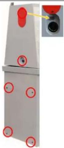
natural_image
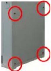
Exterior view of a gray metal panel with four red-circled mounting holes (no text or symbols)The coolant tank is located in the right foot of the machine, below the tailstock. Loose the 4 Allen screws and remove the cover.
Check the coolant at regular intervals. Make sure that:
• there is sufficient coolant available,
• the chip mirror in the first chamber is not too high and
• the coolant is not rancid or contaminated.
Apply coolant
- Make sure that the coolant tank is properly maintained and filled.
- Position the coolant nozzle as required for your operation.
- Use the switch on the control panel to turn the coolant pump on or off.
- Use the flow valve to regulate the flow of coolant.
17.2.9 Function test
Check all spindles for ease of movement!
17.3 Electrical connection
WARNING

Dangerous electrical voltage! Connection of the machine as well as electrical inspections, maintenance and repair may only be carried out by qualified personnel or under the supervision and supervision of a qualified electrician!
- Check that the neutral connection and protective earthing are functioning properly
- Check that the supply voltage and current frequency correspond to the specifications of the machine
NOTICE

Deviation of the supply voltage and current frequency
A deviation from the value of the supply voltage of ±5% is permissible.
A short-circuit fuse must be provided in the power supply system of the machine!
- Find the required cross-section of the supply cable (it is recommended to use a cable type H07RN, taking measures to protect against mechanical damage) in a current capacity data sheet.
NOTICE

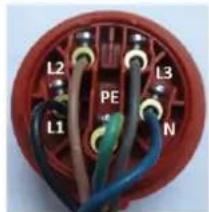
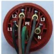
Rotary current machines must always be connected to 3 phases and a protective wire (PE). Check the correct running direction of the machine immediately after making the electrical connection! The jaw chuck must rotate counterclockwise when the gear lever on the lock case is lowered. If necessary, replace two of the three phases (L1/L2 or L1/L3)!
- Connect the supply cables to the corresponding terminals in the input box (L1, L2, L3, N (if necessary), PE). If there is a CEE plug, the connection to the mains is made by an appropriately supplied CEE coupling (L1, L2, L3, N, PE).
Plug connection 400V:
5-wire:
with
N conductor
text_image
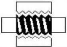
L2 L3 PE L1 N4-wire:
without
N conductor
text_image
L2 PE L3 L1 N18 OPERATION
18.1 Operations preparation
Check Screw Connections
Check all bolted connections and tighten if necessary.
Check Oil Levels
Check the oil levels and top up with oil if necessary.
Check Coolant
Check the coolant level and top up the coolant if necessary.
18.2 Retracting the machine
NOTICE

Never shift the gears of the machine while the machine is in operation and make sure that both the shift lever tapping (lock nut) and the engaging lever cross feed - longitudinal feed are disengaged before putting the machine into operation! Otherwise the carriage may be pushed forward into the chuck or tailstock and cause serious damage.
WARNING

Before starting the machine, make sure that you have followed all assembly and adjustment instructions, that you have read the instructions and that you are familiar with the various functions and safety features of this machine. Disregarding this warning may result in serious injury or even death!
After assembly is complete, test the machine to ensure that it is functioning properly and ready for regular operation. This is done without a clamped workpiece. Perform the test as described below.
18.2.1 Performing a test run
- Make sure that you have understood the safety instructions in this manual and that all other assembly steps have been completed.
- Make sure that the necessary operating liquids (gear oil, coolant, etc.) have been filled up.
- Make sure that the chuck is correctly fastened.
- Make sure that all tools and objects used during setup are removed from the machine.
- Release the shift lever tapping (lock nut) (Q) and the engaging lever cross feed - longitudinal feed (R)
- Make sure that the coolant pump (C) is switched off; direct the coolant nozzle into the chip tray of the machine.
- Turn the Emergency Stop (G) clockwise until it pops out.
- Move the shift lever feed direction (A) to the disengaged centre position.
- Set the machine to the lowest speed.
- Connect the machine to the power source and then turn the main power switch to the ON position and the motor-step-switch to position "I".
- Press the shift lever rotating direction (P) to start the machine. The spindle rotates at 45 rpm. When properly operated, the machine runs smoothly with little or no vibration or friction.
- Move the shift lever rotating direction (P) to the center position and press the Emergency Stop button (G).
- Without resetting the Emergency Stop button, move the shift lever rotating direction down. The machine must not start.
If this is the case, the safety function of the Emergency Stop button is guaranteed. Continue with the next step.
However, if the machine starts with the Emergency Stop button pressed in, disconnect the power supply to the machine immediately. The Emergency Stop button does not function properly. In this case contact the customer service. - Turn the Emergency Stop button clockwise until it pops out.
- Make sure that the power indicator light (B) is working.
- Ensure that the coolant nozzle is pointing towards the chip pan, then turn the coolant pump switch and open the nozzle valve. After checking that the coolant is flowing out of the nozzle, turn off the coolant switch.
- Start the spindle and then apply the foot brake. The power supply to the motor should be interrupted and the spindle should stop immediately.
The retraction must be carried out at the lowest spindle speed. Let the machine run at this speed for about 1 hour. Pay attention to any abnormalities and/or irregularities, such as unusual noises, unbalance, etc. If everything is OK, gradually increase the speed. The highest speeds may only be reached after 10 hours of operation.
If unusual noises or vibrations occur during the test run, stop the machine immediately and read the Troubleshooting section. If you cannot find a remedy, contact your specialty retailer or customer service.
18.3 Operating the machine
18.3.1 Control icons
 | motor-step-switch0: Off1: Step 1II: Step 2 |  | Coolant pumpGreen: OnRed : Off |
 | Half nut opened | 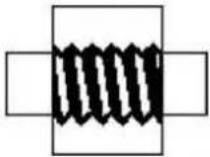 | Half nut closed |
 | Metric thread |  | Imperial thread |
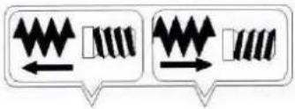 | Right-hand thread and longitudinal feed to the headstock side (left illustration) | ||
| Left-hand thread and longitudinal feed to tailstock side (right picture) | |||
 | Longitudinal feed engaged (top)Both feeds disengaged (middle)Cross feed engaged (bottom) |  | Oil inlet |
 | Do not change speed or direction of rotation during operation! | ||
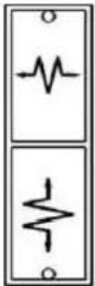
| [A5BD] | Electric voltage |  | Intermittent push button |
 | Power indicator light |  | Emergency-Stop |
18.3.2 Switching on the machine
NOTICE

Note that the machine can only be started if the EMERGENCY STOP is unlocked, the jaw chuck guard is closed and all position switches are activated.
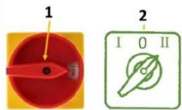
text_image
1 2 I O II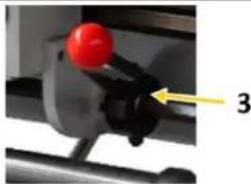
natural_image
Close-up of a mechanical component with a red knob and a yellow arrow pointing to part 3 (no text or symbols visible)18.3.3 Intermittent push button
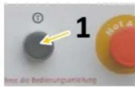
The machine is equipped with an intermittent push button (1) for convenient change of the main spindle speed, confirmation of the feed rate and centring of objects. If the button is pressed, the main spindle immediately turns forward and stops as soon as you release the button.
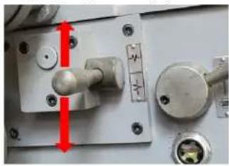
18.3.4 Foot brake
natural_image
3D diagram of a red cable or wire passing through a gray panel, with no visible text or symbolsWhen pushing the foot brake the drive is deactivated and the spindle will be stopped.
The machine is restarted by actuating the switch lever rotating direction of.
- middle position 2. select direction of rotation
18.4 Setting spindle speed and rotation direction
NOTICE


Never change the direction of rotation or speed, as long as the motor / spindle is not at a complete standstill! Changing the direction of rotation / of speed during operation may lead to the destruction of components.
The correct spindle speed is important for safe and satisfactory results and for maximizing tool life. To set the spindle speed correctly, do the following:
• Determine the optimum spindle speed for the machining task in question and
- Set the machine control so that the required spindle speed is actually reached.
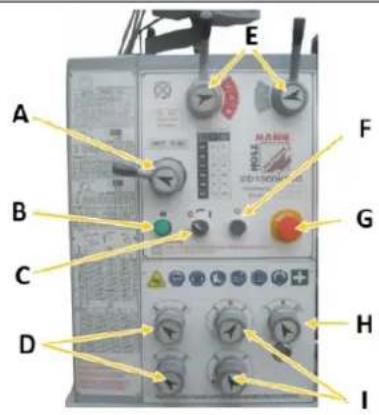
18.4.1 Spindle speed selection
The spindle speed is selected by the two control levers on the headstock and by the motor step switch on the left of the machine housing.
When the motor step switch is set to position "I", lower speed ranges can be selected. When the motor step switch is in position "II", higher speed ranges can be selected.
A total of twelve speeds can be selected:
| Spindle speed selection (min-1) |  |  | |||
 |  |  |  | ||
 | 180 | 1000 | 360 | 2000 | |
 | 65 350 130 700 | ||||
 | 45 | 245 | 90 | 490 | |
Use the intermittent push button to facilitate engagement in the individual switching positions.
18.4.2 Direction of rotation
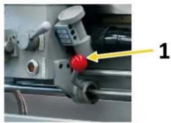
natural_image
Close-up of a mechanical component with a red knob and yellow arrow pointing to it (no visible text or symbols)The shift lever for the direction of rotation (1) is used to shift the machine. If you put the switch down, the jaw chuck runs counterclockwise. If you place the switch upwards, the jaw chuck runs clockwise.
18.4.3 Running operation
Only use chucks recommended by Holzmann Maschinen.
The maximum spindle speed for the 320 mm diameter face plate should not exceed 1255 min ^-1 . When threading or automatic feed is not in use, the selector lever feed direction should be in the neutral position to ensure disconnection of the lead screw and the feed screw. To avoid unnecessary wear, the thread dial indicator should not be connected to the lead screw.
18.5 Threads and feeds
18.5.1 Change gear gearbox
For optimum adaptation to the respective requirements for threading, the change-gear gearbox must be set according to the data scale. A large number of feeds and most thread pitches can be set with the factory fitted change gears. For special feeds or thread pitches, the required change gears must be changed.
WARNING

Switch off the machine before replacing or changing the position of the change wheels and secure it against unauthorised or unintentional recommissioning.
The change gears for the feed are mounted on a change gear shear or directly on the lead screw and the feed gear.
In order to obtain the desired thread according to the table, the corresponding gearwheel combinations must be mounted beforehand:
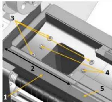
text_image
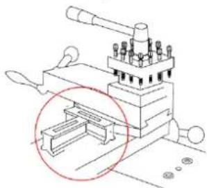
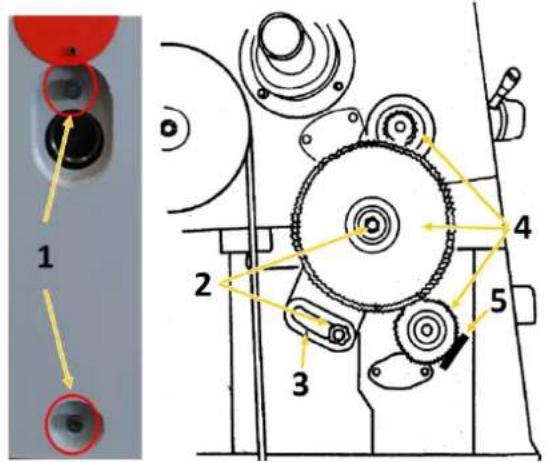
1 2 3 4 5- Disconnect the machine from the power source and secure it against unintentional start-up.
- Loose the screws (1) and remove the cover on the left side of the headstock.
- Loosen the hexagon nuts (2) and the Allen screw (5) and move the swing frame (3) out of the way.
- Change the gear wheels (4) according to the feed or thread table.
- Position the swing frame so that the large gear wheel meshes with the smaller gear wheels. Then tighten. Make sure that there is a clearance of 0.005 - 0.007 mm between the gears. (Adjusting the gears too tightly will result in excessive noise and increased wear.)
- Remount the cover (pay attention to the position switch!) and reconnect the machine to the power source.
18.5.2 Manual feed
text_image
Labeled mechanical assembly diagram showing numbered components and directional arrows- The manual feed of the longitudinal slide is carried out by means of handwheel (1).
- The manual feed of the cross slide is carried out by means of handwheel (2).
- The manual feed of the top slide is carried out by means of handwheel (3).
18.5.3 Automatic feeds
NOTICE


Disconnect the machine from the mains and wait until the machine has come to a complete standstill before making any changes to the switching positions of the selector levers. If necessary, use the intermittent push button to assist in engaging a lever.
The feed spindle is switched on via the feed direction selector lever (A) on the headstock and thus determines the feed direction.
Move the selector lever to the left or right according to the symbols.
Use selector switches (D, H, I) to set the desired feed rate or thread pitch.
The selectable feed rates for longitudinal feed range from 0,02 to 0,85 mm/r.
The selectable feed rates for cross feed range from 0,005 to 0,22 mm/r.
Use the tables on the side of the housing of the gearbox to set the desired feed rate.
LEVER = selector switch
T = number of teeth; e.g. 60T
text_image
A B C D E F G H ICross or longitudinal feed: engaging lever (R)
natural_image
Close-up of a mechanical component with red arrows indicating direction, no visible text or symbols18.5.4 Cutting threads
The machine can be used to cut metric or inch threads. With the feed direction selector lever (A) on the headstock, you can set the direction of rotation for threading (left/right thread). You can set the pitch with the feedrate selectors. The shift lever tapping (lock nut) (Q) must always be closed during the thread cutting process.
18.5.5 Thread pitch table / longitudinal feed for metric threads
The metric threads range from 0.8 to 14.0 mm, 36 steps are available.
 |  Lead screw pitch 6mm Lead screw pitch 6mm | |||||||||
| change gear a-no. of teeth- | 56 | 60 | 60 | 40 | 60 | 60 | 40 | 60 | 56 | |
| Change gear b-no. of teeth- | 60 | 60 | 60 | 80 | 60 | 60 | 80 | 60 | 63 | |
| lever | 4 | 1 | 3 | 4 | 1 | 3 | 1 | 3 | 3 | |
| R | R | S | T | V | R | T | V | V | ||
| A | D | 14.0 | 12.0 | 11.2 | 10.0 | 9.6 | 9.0 | 8.0 | 7.2 | 6.4 |
| B | D | 7.0 | 6.0 | 5.6 | 5.0 | 4.8 | 4.5 | 4.0 | 3.6 | 3.2 |
| A | C | 3.5 | 3.0 | 2.8 | 3.5 | 2.4 | 2.25 | 2.0 | 1.8 | 1.6 |
| B | C | 1.75 | 1.5 | 1.4 | 1.75 | 1.2 | 1.12 | 1.0 | 0.9 | 0.8 |
18.5.6 Thread pitch table / longitudinal feed for imperial threads
Imperial threads range from 2 to 28 TPI, 30 steps are available.
Lead screw pitch 6mm
| change gear a -no. of teeth- | 60 | 60 | 60 | 60 | 60 | 56 | 60 | 60 | |
| Change gear b -no. of teeth- | 60 | 54 | 57 | 60 | 66 | 54 | 78 | 63 | |
| lever | 4 | 1 | 1 | 1 | 1 | 2 | 1 | 3 | |
| V | V | V | V | V | V | V | V | ||
| A | D | 2 | 214 | 212 | 234 | 3 | 314 | 312 | |
| B | D | 4 | 412 | 5 | 512 | 6 | 612 | 7 | |
| A | C | 8 | 9 | 912 | 10 | 11 | 12 | 13 | 14 |
| B | C | 16 | 18 | 19 | 20 | 22 | 24 | 26 | 28 |
18.5.7 Thread dial indicator (for resumption of the pitch)
NOTICE

Do not engage the lock nut if the lead screw rotates at more than 200 revolutions per minute or if the carriage lock is locked, otherwise damage may be caused to the bearings or the shear pin of the spindle may break!
natural_image
Close-up of a mechanical assembly with numbered components and directional arrows (no readable text or symbols)1
The thread dial indicator (1) can also be used for cutting metric threads. The thread dial indicator (to resume the pitch) is located on the right of the apron.
The thread dial indicator has an important function. It indicates the correct moment to engage the "shift lever tapping (lock nut)" (2), so that the tool takes up the same turn again at each step.
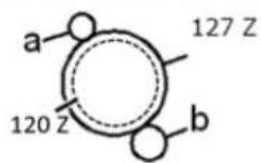
On the lower end of the thread dial indicator shaft there are several gear wheels with different numbers of teeth to be able to turn metric threads with different thread pitches. The vertical position of the thread dial indicator is changed as required so that the gear selected for the desired thread pitch engages with the lead screw.
text_image
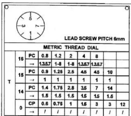
LEAD SCREW PITCH 6mm METRIC THREAD DIAL T 16 PC 0.8 1.2 2 4 8 → 1.357 1-8 1-8 1.357 1.357 15 PC 0.9 1.25 2.5 4.5 4.5 10 → 1 1 1 1 1 1 14 PC 1.4 1.75 2.8 3.5 7 14 → 1.5 1.5 1.5 1.5 1.5 1.5 0 CP 0.6 0.75 1 1.5 3 3 12 → / / / / / / / /On the dial of the thread gauge there are the numbered lines 1, 3, 5 and 7. In between there are lines without numbering, so called half lines. When the lead screw is engaged, the dial rotates.
There is only one line mark (fixed line) on the housing of the thread dial indicator.
The table on the side of the gearbox housing (see illustration on the left) shows the pitch, the selection and the coupling sequence of the marks on the rotating dial with the fixed mark. The numbers in the line "→" refer to the numbering of the graduation marks on the thread dial indicator. For threading, engage the lock nut at the height of the corresponding number indicated in the table.
18.6 Tool post
The main function of the tool post is to fix the tool. If necessary, the tool post can also hold more than one tool (maximum 4).
When inserting the tool, make sure that the cutting head of the tool points in the direction of the rotation axis of the workpiece.
Tool change
CAUTION

Before any manual tool change, stop the spindles, wait for all tools to come to a standstill and secure the machine against unintentional restarting before changing the tools!
text_image
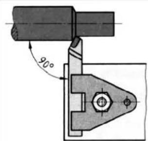
90°Clamp the turning tool into the tool post (L).
The turning tool must be clamped as short and tightly as possible in order to be able to absorb the cutting force occurring during chip formation well and reliably.
Also ensure that the turning tool is clamped at a right angle to the axis of rotation (see illustration on the left). When clamping at an angle, the turning tool can be pulled into the workpiece.
Align the turning tool in height. Use the tailstock with centering point to determine the required height. If necessary, place steel supports under the lathe tool to obtain the required height.
natural_image
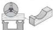
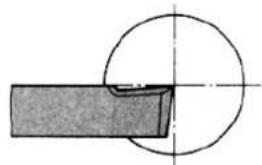
Pure mechanical diagram showing a circular component intersecting a rectangular block (no text or symbols)The cutting edge of the turning tool must be set exactly to centre height during facing so that the face is free of studs. Facing produces flat surfaces perpendicular to the workpiece axis of rotation. A distinction is made between transverse face turning, transverse cut-off turning and longitudinal face turning.
natural_image
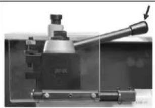
Close-up of a mechanical tool with a lever and base mount (no visible text or symbols)If the tool post must be turned, open the clamping lever by turning it counterclockwise. Turn the tool post to the desired position and then tighten it again by turning the clamping lever clockwise.
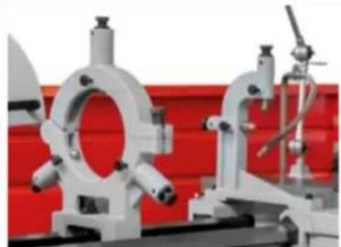
18.7 Mounting steady or follow rests
natural_image
Industrial mechanical components with white brackets and red background (no visible text or symbols)Use steady or follow rests to support long turned parts if the cutting force of the turning tool is likely to cause the turned part to deflect.
18.8 Tailstock
natural_image
Close-up of a mechanical testing machine with labeled components (1, 2), no visible text or symbols beyond labels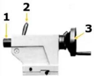
text_image
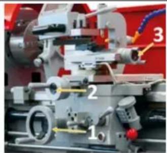
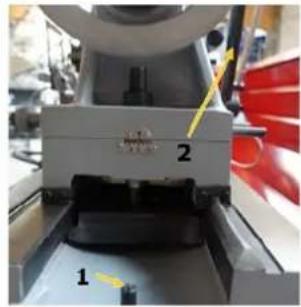
1 2 3The tailstock serves as a counter bearing when turning between the centres as well as for holding drilling, countersinking and reaming tools. It is guided on the cheeks of the machine bed and can be clamped at any point by a clamping lever (2).
The tailstock is secured in the machine bed (cast bed) with an end position stop screw (1) to prevent the tailstock from sliding out unintentionally (see picture on the left).
The tailstock spindle sleeve (1) can be moved by a threaded spindle and a handwheel (3) and can be clamped with a clamping lever (2). An inner taper in the quill accommodates the centering point, a drill chuck or tools with a tapered shank.
- Clamp your required tool into the tailstock sleeve.
→ Use the scale on the sleeve for adjustment and/or readjustment. - Clamp the sleeve with the clamping lever.
→ Use the handwheel to retract and extend the tailstock sleeve.
18.8.1 Tailstock laterally offset
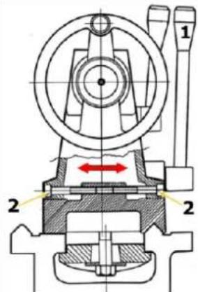
text_image
Technical diagram of a mechanical device with labeled parts and directional arrows indicating motion or flow.The transverse displacement of the tailstock is necessary, for example, when turning long, conical bodies.
Loosen the tailstock clamping lever (1) and the adjusting screws (2) on the left and right of the tailstock.
The desired transverse offset can be set with the help of the scale on the back of the tailstock.
Finally retighten adjusting screws and clamping lever.
18.9 Gap
text_image
Technical diagram of a mechanical assembly with numbered components and directional arrows indicating motion or flow.The turning diameter can be increased by removing the gap (1). Max. turning diameter without gap and length of the bed gap (2) can be found in the technical data.
The max. turning length depends on the used workpiece holder.
- Place the longitudinal stop (if available) first on the right side of the machine bed (5).
- First loosen the fixing screws (3) and then pull out the locating pins (4).
• Proceed in the reverse order when reassembling.
18.10 General working instructions
WARNING

Do not clamp workpieces that exceed the permissible clamping range of the workpiece holders, lathe chucks, etc. The clamping force of a lathe chuck is too low when the clamping range is exceeded. The clamping jaws can become loose.
CAUTION

Regularly check the closed condition of the clamping bolts.
The workpieces must be clamped securely and firmly on the machine before machining. The clamping force should be dimensioned in such a way that the workpiece can be securely gripped, but no damage or deformation of the workpiece occurs.
Clamping the workpiece
- Disconnect the machine from the mains.
- Place a stable board or chuck cradle under the spindle to protect the precision-ground surfaces.
- Insert the chuck key into a scroll groove and turn it counterclockwise to open the jaws until the workpiece lies flat on the clamping surface or evenly on the jaw steps or fits into the chuck hole and through the spindle hole.
- Close the jaws until they make light contact with the workpiece.
- Turn the chuck by hand to ensure that the workpiece is held evenly by all three jaws and centred on the chuck.
If the workpiece is not centred, release the jaws and realign the workpiece. Retighten the jaws and repeat step 5. When the workpiece is centred, fully tighten the jaws.
18.10.1 3-jaw chuck
The 3-jaw chuck supplied with your machine is a scroll chuck, i.e. all three jaws move uniformly when the chuck key is turned. This jaw configuration is used to hold concentric workpieces that are centred with the same pressure from all three jaws. A set of reversible top jaws is also included to allow additional workpiece configurations.
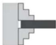
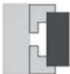
Clamping on an Outside Diameter

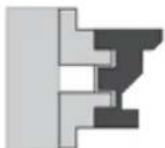
Clamping in an Inside Diameter
Both sets of jaws can accommodate a workpiece on both the inside and outside - see illustration on the left. Regardless of how you configure the jaws, make sure the workpiece is firmly clamped in the jaw chuck.
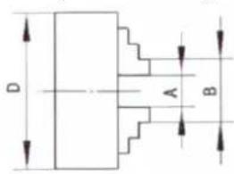
text_image
D A B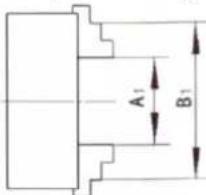
text_image
A₁ B₁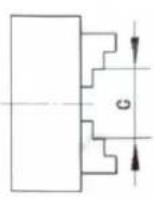
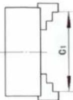
| ∅ D | A - A1 | B - B1 | C - C1 |
| 200 mm | 4 - 120 mm | 50 - 220 mm | 60 - 230 mm |
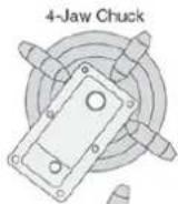
18.10.2 4-jaw chuck
WARNING

Use the 4-jaw chuck only for low-speed turning operations. If the 4-jaw chuck is used at medium or high speed, unbalance will almost always occur and the operator or bystanders may be hit by an ejected workpiece.
natural_image
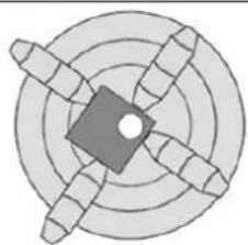
Circular diagram with concentric rings and radial segments, no text or symbols presentThe 4-jaw chuck has independently adjustable jaws. This means that non-cylindrical parts can be held for facing or drilling and brought into the spindle centre line. A further advantage is that the majority of workpieces can be positioned outside the spindle rotation axis, e.g. when a hole or step on an outer edge has to be cut into a workpiece. For optimum grip on non-cylindrically shaped workpieces, one or more jaws can also be rotated 180^ to gain more clamping area.
18.10.3 Face plate
WARNING

When using the face plate, always use at least three independent clamping devices. Insufficient clamping can cause the workpiece to be thrown away during operation!
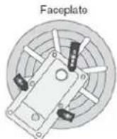
YES
NO
The face plate has several slots for T-bolts which can accommodate clamping devices. Always use the face plate when you think that the 3- or 4-jaw chuck cannot hold the workpiece securely enough - see illustration on the left.
Mounting the face plate
- Disconnect the machine from the mains!
- Insert a dead centre into the tailstock, push the tailstock up to the face plate and lock the tailstock in position.
- Place the workpiece on the face plate, turn the tailstock sleeve so that the dead centre touches the workpiece.
- Lock the quill when enough pressure is applied to hold the workpiece. Additional support may be required depending on the workpiece.
- Clamp the workpiece in at least three locations as evenly spaced as possible - see illustration above.
- Re-check all safety precautions and the backlash.
- Slide the tailstock away from the workpiece and mount the required tailstock tools for drilling or boring or position the chisel for turning.
18.10.4 Longitudinal turning
text_image
FeedDuring facing, the planer tool is moved parallel to the axis of rotation. The feed is carried out either manually by turning the handwheel on the lathe slide or on the upper slide or by switching on the automatic feed. The infeed for the cutting depth is effected via the cross slide.
18.10.5 Plain turning and recessing
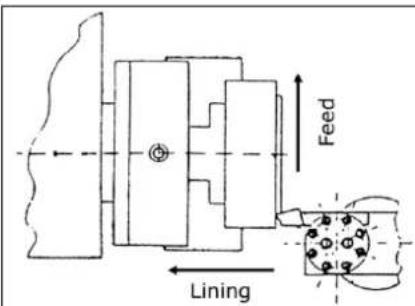
text_image
Feed LiningWhen facing, the turning tool is moved at right angles to the axis of rotation. The feed is done manually with the handwheel of the facing slide. The feed of the cutting depth is effected by the top slide or the bed slide.
18.10.6 Fixing the lathe slide
text_image
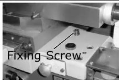
Fixing Screw™The cutting force occurring during facing, grooving or cutting-off operations can cause the lathe slide to move. Therefore fasten lathe slide with the fixing screw.
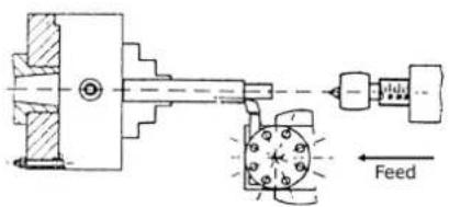
18.10.7 Turning between tips
text_image
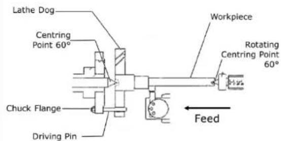
Lathe Dog Centring Point 60° Chuck Flange Driving Pin Workpiece Rotating Centring Point 60° FeedWorkpieces that require a high concentricity are machined between the tips. A centre hole is drilled in both face turned faces of the workpiece. The turning heart is clamped onto the workpiece. The driving pin, which is screwed into the chuck flange, transmits the torque to the rotary heart. The fixed centering point is located in the centre hole of the workpiece on the spindle head side. The rotating center point is located in the centering hole of the workpiece on the tailstock side.
18.10.8 Turning short taper with the top slide
text_image
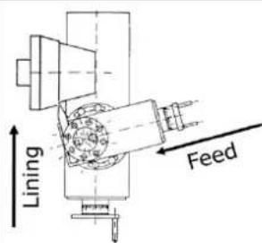
Lining FeedThe short taper is turned by hand with the top slide. The upper slide is swivelled according to the desired angle. The infeed takes place with the cross slide:
natural_image
Close-up of a mechanical assembly with red arrows pointing to specific components (no visible text or symbols)- Loosen the two clamping screws at the front and rear of the upper slide.
- Turn the upper slide to the desired position.
- Clamp the upper slide again.
18.10.9 Thread cutting
text_image
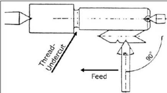
Thread- Undercut Feed 90°Threading or tapping requires good turning skills and sufficient experience from the operator.
See the following example
Example outside thread:
• The workpiece diameter must be turned to the diameter of the desired thread.
- The workpiece requires a chamfer at the beginning of the thread and an undercut at the end of the thread.
• The speed must be as low as possible.
- The thread chisel must correspond exactly to the thread form, be absolutely right-angled and clamped exactly to the turning centre.
- The engagement lever for thread cutting must remain closed during the entire thread cutting process. Excluded are the thread pitches which can be carried out with the tapping watch.
- The thread is produced in several cutting operations, so that the turning tool must be completely turned out of the thread (with the facing slide) at the end of a cutting operation.
- The return path is made with the clasp nut closed and the thread turning tool not engaged by actuating the "Shift lever Direction of rotation".
- Switch off the machine and reposition the chisel in small cutting depths with the cross slide.
- Before each run, adjust the upper slide by approx. 0.2 to 0.3 mm alternately to the left and right in order to free the thread. The thread chisel therefore only cuts on one thread flank in each pass. Do not cut free until shortly before reaching the full thread depth.
19 CLEANING
NOTICE

Wrong cleaning agents can attack the varnish of the machine. Do not use solvents, nitro thinners, or other cleaning agents that could damage the machine's paint. Observe the information and instructions of the cleaning agent manufacturer!
Prepare the surfaces and lubricate the bare machine parts with an acid-free lubricating oil. Regular cleaning is a prerequisite for the safe operation of the machine and its long service life. Therefore, clean the device after each use of chips and dirt particles.
20 MAINTENANCE
WARNING

Danger due to electrical voltage! Handling the machine with the power supply up may result in serious injury or death. Always disconnect the machine from the power supply before servicing or maintenance work and secure it against unintentional restart!
The machine is low-maintenance and only a few parts have to be serviced. Nevertheless, any faults or defects which may affect the safety of the user must be rectified immediately!
-
Before each start-up, make sure that the safety devices are in perfect condition and function properly.
• Check all connections for tightness at least once a week. -
Regularly check that the warning and safety labels on the machine are in perfect and legible condition.
• Use only proper and suitable tools.
• Only use original spare parts recommended by the manufacturer.
20.1 Inspection and maintenance plan
The type and degree of machine wear depends to a large extent on the operating conditions. The following intervals apply when the machine is used within the specified limits:
| Interval | Component | What to do? |
| Before start of work or after every maintenance or servicing | Guideways oiling | |
| Change Gears lubricate | lightly with grease | |
| CamlockClamping BoltsTurning SpindleAdapter | Check fastening | |
| Feed gearApronHead Stock | Visual inspection of the oil levels (via sight glass) | |
| Weekly | Lead ScrewFeed ShaftTailstock | Grease or fill all grease nipples and lubricators with machine oil. |
| Top SlideCross SlideLathe Slide | Grease or fill all grease nipples and lubricators with machine oil. | |
| Annually or after every 1000 operating hours | Feed GearApronHead Stock | Change oil |
| As needed | Guideways Adjust taper | gib |
| Head Stock | Check V-belt and tighten if necessary | |
| Coolant Fill in |
20.1.1 Adjusting the taper gibs
text_image
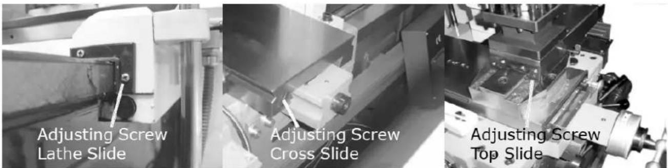
Adjusting Screw Lathe Slide Adjusting Screw Cross Slide Adjusting Screw Top SlideToo much play in the guideways can be reduced by adjusting the taper gibs. To adjust, turn the adjustment screw clockwise. This pushes the taper gibs backwards and reduces the clearance of the respective guideway.
20.1.2 Visual inspection of oil levels
natural_image
Close-up of a mechanical component with a highlighted circular feature (labeled '1') and an arrow pointing to it, no readable text or symbols present.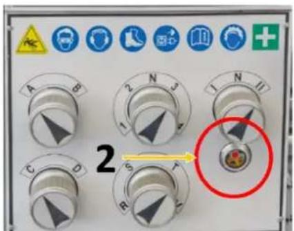
text_image
2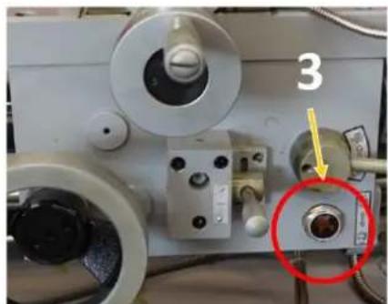
natural_image
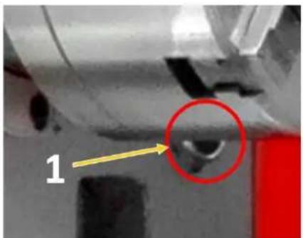
Close-up of a mechanical device with labeled component '3' and a red circle highlighting a specific part (no readable text or symbols beyond the number)Check oil levels of headstock (1), feed gear (2) and apron (3) before starting work or after every maintenance and repair. Oil level must reach at least to the middle or top mark.
20.1.3 Oil change headstock, feed gear and apron
NOTICE


Lubricants are toxic and must not be released into the environment. When changing, use suitable collecting containers with sufficient volume! Follow the manufacturer's instructions and, if necessary, contact your local authority for further information on proper disposal.
Supply gear oil (recommended for ISO 12925-1 CKD, DIN51517 Part 3 CLP, US Steel 224, AGMA 9005-E02) with a viscosity of 220.
text_image
F 1 3 F D 2 DHeadstock (1)
The bearing of the headstock is in an oil bath. Make sure that the oil level always reaches the mark of the sight glass. To change the oil remove the cover on the left side of the headstock, drain the oil by removing the drain plug (D). To refill the oil use the refill opening (F). Remount the cover. Check the oil level regularly.
First oil change (running-in oil) after 100 operating hours, then change the oil once a year or after 1000 operating hours.
Feed gear (2)
Make sure that the oil level always reaches the mark of the sight glass. To change the oil remove the cover on the left side of the headstock, drain the oil by removing the drain plug (D). To refill the oil use the refill opening (F). Remount the cover. Check the oil level regularly.
First oil change (running-in oil) after 100 operating hours, then change the oil once a year or after 1000 operating hours.
Apron (3)
The oil must reach the mark in the oil sight glass. To change the oil, drain the oil by removing the drain plug (D). To refill the oil use the refill opening (F). Check the oil level regularly.
First oil change (running-in oil) after 100 operating hours, then change the oil once a year or after 1000 operating hours.
20.1.4 Other lubrication points
Gear wheels
Lubricate the gears with a heavy, non-spinning grease. Make sure that no grease gets onto belt pulleys or belts!
Grease nipples and lubricators
natural_image
Technical line drawing of a mechanical assembly with gauges and rollers (no text or symbols)Lubricate or fill grease nipples or oilers on the lead screw and feed rod, on the tailstock as well as on the face and top slides with machine oil weekly.
20.1.5 Checking and cleaning the coolant system
NOTICE


Coolants are toxic and must not be released into the environment! Follow the manufacturer's instructions and contact your local authority for information on proper disposal if necessary.
Checking the coolant system
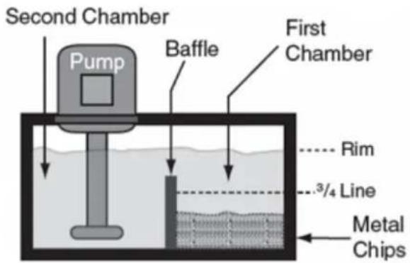
text_image
Second Chamber Pump Baffle First Chamber Rim 3/4 Line Metal Chips- Open the cover to the pump chamber/coolant tank.
- Check the coolant level in the tank. The liquid should be about one centimetre below the top edge of the tank.
- Check the level of the metal chips in the first chamber. When the chips have reached 3/4 the height of the partition, remove the chips.
- Check the quality of the coolant according to the manufacturer's instructions and replace it as recommended.
Cleaning the coolant system
- Empty any residual coolant still contained in the coolant nozzle into the drain container.
- Lift the tank assembly out of its anchorage.
- Remove all metal chips and remaining coolant and clean the tank.
- Clean the suction strainer on the pump.
- Reinstall the coolant tank in its original place.
- Fill the tank with fresh coolant.
- Properly mount the cover to the pump chamber.
20.1.6 Replacing the V-belt
NOTICE

Never replace V-belts individually but only as a complete set!
natural_image
Exterior view of a mechanical or electrical component with red circular markers and a highlighted pin (no text or symbols visible)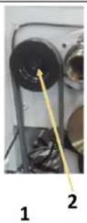
natural_image
Close-up of a mechanical component with two circular holes and a yellow arrow pointing to a textured surface (no visible text or symbols)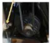
- Open the screws on the covers and remove them.
- Loosen the adjusting nut (1) on the motor frame and decrease the V-belt
■ Loosen the Allen screw (2) and remove the belt pulley.
■ Change the V-belts
■ Tighten the V-belts.
→The tension is correct when a single V-belt can only be pushed through a maximum of 5 mm with the thumb. - Tighten the adjusting nuts again.
■ Remount the cover (pay attention to the position switch!)
20.1.7 Replacing jaws
To replace the jaws, you must open the lathe chuck with the chuck key. In the fully open position, the jaws can then be removed one by one.
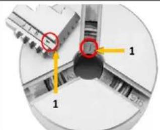
text_image
Technical diagram showing a mechanical component with labeled parts and directional arrows, including red circles highlighting specific features.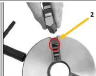
natural_image
Close-up of a hand using a tool to adjust or install a CD or DVD drive, with a highlighted section showing a red arrow and number 2 (no text or symbols on the device itself)The following must be observed when inserting the jaws:
- The threaded segments (2) of the jaws are graduated as shown in the figure.
- In addition, they are numbered (1) from 1 to 3 to indicate the actual pitch in the lathe chuck.
Therefore, make sure to mount the jaws in the correct order:
- Arrange the jaws as shown in the figure above and insert them clockwise into the slots of the lathe chuck in this order.
- Hold the jaws and clamp them with the chuck key.
- Close the chuck completely and check that the jaws meet in the middle.
If a jaw does not fit properly, open the lathe chuck, press firmly on the jaw and turn the chuck key until the jaw is in the correct position. Check again that the jaws meet in the middle.
20.1.8 Adjusting the overload clutch on the feed spindle
NOTICE

Never fully tighten the overload clutch set screw beyond the normal setting described in this procedure. Severe gear damage could result.
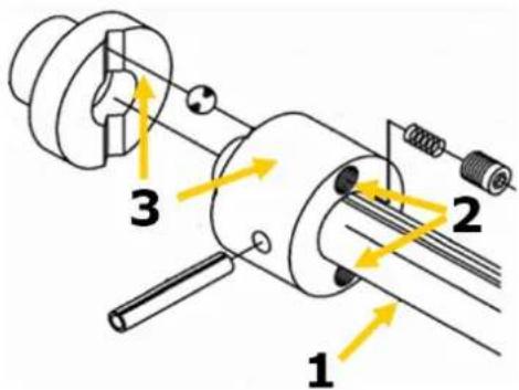
text_image
1 2 3The lathe is equipped with a spindle (1) overload clutch (3), which connects the drive hub to the feed spindle by means of a set of spring-loaded internal balls. This coupling helps to protect the lock case from overload and the machine from damage. The feed screw coupling is set at the factory, and if only readjusted when there is a problem, the coupling can be adjusted to the required position.
The clutch slips, for example, if the path of the longitudinal or transverse slides is obstructed, if the tool collides with a workpiece shoulder, if the slide lock is actuated from the left when the feed selector lever is engaged, or if the cut is too deep.
Adjusting the clutch:
Disconnect the machine from the mains!
If the clutch slips under normal working load and there is no problem with the feed system, the clutch spring pressure must be increased. To do this, tighten the two set screws (2) one eighth of a turn and check the clutch again for slippage.
If, for any reason, the clutch becomes jammed or stuck and does not slip if it should, the clutch spring pressure must be reduced. To do this, loosen the two set screws (2) by one eighth of a turn and then check again for slippage.
21 STORAGE
NOTICE

Improper storage can damage and destroy important components. Only store packed or unpacked parts under the intended environmental conditions!
When the machine is not in use, store it in a dry, frost-proof and lockable place to prevent the formation of rust on the one hand and to ensure that unauthorised persons and in particular children have no access to the machine on the other hand.
22 DISPOSAL

Observe the national waste disposal regulations. Never dispose of the machine, machine components or equipment in residual waste. If necessary, contact your local authorities for information on the disposal options available.
If you buy a new machine or an equivalent device from your specialist dealer, he is obliged in certain countries to dispose of your old machine properly.
23 TROUBLESHOOTING
WARNING

Danger due to electrical voltage! Manipulating the machine with the power supply up may result in serious injury or death. Before carrying out any troubleshooting work, always disconnect the machine from the power supply and secure it against unintentional recommissioning.
Many possible sources of error can be excluded in advance if the machine is properly connected to the mains.
If you are unable to carry out necessary repairs properly and/or do not have the required training, always consult a specialist to solve the problem.
| Fault Possible cause Remedy | ||
| Machine does not start | Machine is not connectedFuse or contactor brokenCable damagedSafety device not locked | Check all electrical connectionsChange fuse, activate contactorReplace cableCheck spindle protection / gearbox cover |
| Machine does not reach speed | Extension cable too longMotor not suitable for existing voltageweak power network | Exchange to suitable extension cableSee switch box cover for correct wiringContact electrician |
| Machine vibrates strongly | Stands on uneven groundMotor mounting is loose | Level newTighten the fixing screws |
| Lathe tool has a short tool life | Hard cast skinToo high cutting speedToo large infeedToo little cooling | Break casting skin beforehandChoose lower cutting speedLower infeed (finishing allowance)not more than 0.5 mm)More cooling |
| Cutting edge breaks out | Wedge angle too small (heat build-up)Abrasive cracks due to incorrect coolingToo much play in the spindle bearing (vibrations occur) | Select a larger wedge angleUniform coolingAdjust play in the spindle bearing. Replace tapered roller bearing if necessary. |
| Turned thread is wrong | Thread chisel is incorrectly clamped or incorrectly groundIncorrect thread pitchIncorrect diameter | Set lathe tool to centreGrinding angles correctlySet the correct gradientPre-turn workpiece to exact diameter |
24 AVANT-PROPOS (FR)
Cher client, chère cliente,
25.1.1 Restrictions techniques
natural_image
Industrial machine with control panel and yellow warning labels (no readable text or symbols)
natural_image
Line drawing of a lathe machine with levers and control panel (no text or symbols)natural_image
Close-up of a hand holding a small electronic component with a red circle highlighting it (no visible text or symbols)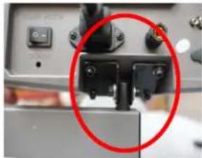
natural_image
Close-up of a mechanical device with a red circle highlighting a component (no visible text or symbols)
natural_image
Close-up of a server rack with connected cables and ports, labeled 'X', 'Y', 'Z' (no additional text or symbols visible)
natural_image
Laboratory setup with mechanical components and a red circle highlighting a specific area (no visible text or symbols)natural_image
Technical line drawing of a mechanical device with a red circle highlighting a component (no text or symbols present)natural_image
Close-up of a circular mechanical component with red curved arrows indicating rotation or movement (no text or symbols visible)natural_image
Close-up of a circular mechanical component with a square hole and a red circle highlighting a feature, no visible text or symbols.natural_image
Close-up of a metallic mechanical component with a circular hole and red measurement lines (no text or symbols visible)natural_image
Close-up of a metallic mechanical component with a conical tip, no visible text or symbolstext_image
J 1 A 6 inch 150mm B PIN K Jnatural_image
Technical line drawing of a mechanical assembly with no visible text or symbolsVis d'ajustement
natural_image
Close-up of a mechanical component with a highlighted circular feature and number 1, no readable text or symbols present.natural_image
Exterior view of a wall-mounted electronic component with four red-circled mounting holes (no text or symbols visible)natural_image
3D diagram of a red cable or wire inside a white enclosure, with a yellow arrow pointing to it labeled '1' (no text or symbols beyond label)natural_image
Close-up of a mechanical component with a red knob and yellow arrow pointing to it, no visible text or symbols.text_image
Labeled mechanical assembly diagram showing numbered components and directional arrowstext_image
A B C D E F G H Inatural_image
Close-up of a mechanical component with a red vertical arrow and measurement markings (no readable text or symbols)28.5.4 Alésage
text_image
Technical diagram of a mechanical assembly with labeled parts and directional arrows indicating motion or forcetext_image
Technical diagram of a mechanical assembly with numbered components and directional arrows indicating motion or flow.natural_image
Two mechanical component diagrams showing cross-sections of a shaft and housing (no text or symbols)natural_image
Two abstract geometric diagrams with shaded and unshaded regions, no text or symbols present.natural_image
Abstract geometric diagram with concentric circles and radial segments, no text or symbols presentnatural_image
Close-up of a mechanical assembly with red arrows pointing to specific components (no visible text or symbols)natural_image
Technical line drawing of a mechanical assembly with no visible text or symbolsnatural_image
Technical diagram showing mechanical components with numbered annotations (1, 2) and red circles highlighting features, no readable text or symbols present.text_image
Technical diagram showing a mechanical component with labeled parts and highlighted features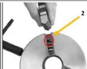
natural_image
Close-up of a hand using a tool to cut a CD or DVD disc, with a highlighted section and arrow indicating direction (no text or symbols present)natural_image
Industrial machine with control panel and yellow warning labels (no readable text or symbols)
natural_image
Line drawing of a lathe machine with levers and control panel (no text or symbols)natural_image
Industrial machine with a red circular annotation highlighting a component (no visible text or symbols)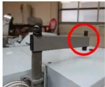
natural_image
Industrial machine with a red circle highlighting a component, no visible text or symbols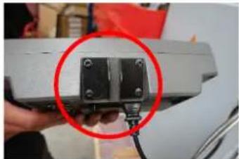
natural_image
Close-up of a hand holding a small black electronic component with a red circle highlighting it, against a white background (no text or symbols visible)
natural_image
Close-up of a mechanical component with a red circle highlighting a detail (no visible text or symbols)
natural_image
Close-up of a network switch with metallic connectors and labeled ports X, Y, Z (no additional text or symbols visible)Montagem DRO
natural_image
Laboratory setup with mechanical components and a red circle highlighting a specific area (no visible text or symbols)natural_image
Technical line drawing of a mechanical device with a red circle highlighting a component (no text or symbols present)natural_image
Close-up of a circular mechanical component with red curved arrows indicating rotation or force direction (no text or symbols)natural_image
Close-up of a circular mechanical component with a central square hole and a red circle highlighting a feature, placed on a metallic surface (no text or symbols visible)natural_image
Close-up of a metallic mechanical component with a central hole and red measurement lines (no text or symbols visible)natural_image
Close-up of a metallic mechanical component with a conical tip, mounted on a workbench (no visible text or symbols)text_image
J 1 A 6 inch 150mm B PIN K Jnatural_image
Technical line drawing of a mechanical assembly with no visible text or symbolsParafusos de ajuste
natural_image
Close-up of a mechanical component with a highlighted circular feature (labeled '1') and an arrow pointing to it, no readable text or symbols present.natural_image
Close-up of a mechanical device with labeled component '3' and a red circle highlighting a small circular feature (no readable text or symbols)natural_image
Close-up of a wall-mounted electronic component with four red-circled mounting holes (no text or symbols visible)Verificar as uniões roscadas
natural_image
3D diagram of a red cable or rod inserted into a white panel, with no visible text or symbolsnatural_image
Close-up of a mechanical assembly with a red knob and yellow arrow pointing to component 1 (no visible text or symbols)text_image
Labeled mechanical assembly diagram showing numbered components and directional arrowstext_image
A B C D E F G H Inatural_image
Close-up of a metallic mechanical component with a red vertical arrow indicating a measurement or assembly (no visible text or symbols)natural_image
Pure mechanical diagram showing a cylindrical component intersecting a rectangular block (no text or symbols)natural_image
Close-up of a mechanical clamp or lever assembly with a handle and base, no visible text or symbolsnatural_image
Industrial mechanical testing setup with white and red components (no visible text or symbols)natural_image
Industrial machine component with labeled parts (1, 2), no visible text or symbols on the main structuretext_image
Technical diagram of a mechanical assembly with labeled parts and directional arrows indicating motion or forcenatural_image
Two abstract mechanical or architectural diagrams with no visible text, numbers, or symbols.Fixação no interior

natural_image
Two abstract geometric diagrams with shaded regions, no text or symbols presentFixação no exterior
natural_image
Circular diagram with concentric rings and radial segments, no text or symbols presentnatural_image
Close-up of a mechanical assembly with red arrows pointing to specific components (no visible text or symbols)40.1.1 Reajustar as barras trapezoidais
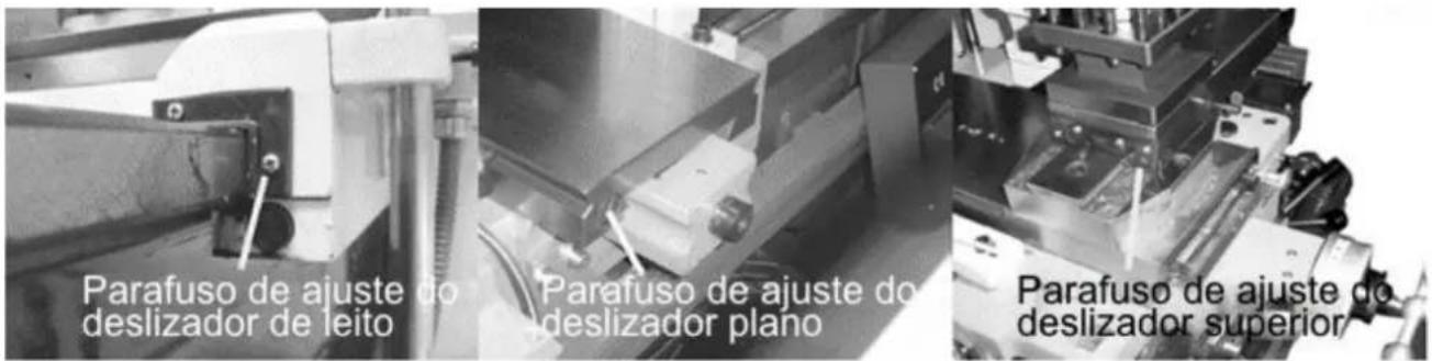
natural_image
Technical line drawing of a lathe machine with gauges and levers (no text or labels)text_image
Technical diagram showing mechanical components with numbered annotations and red circular features, likely from an engineering or manufacturing context.40.1.7 Mudar as mandíbulas
text_image
Technical diagram showing two steps of a mechanical assembly with labeled components and highlighted partsnatural_image
Industrial machine with control panel and yellow warning labels (no readable text or symbols)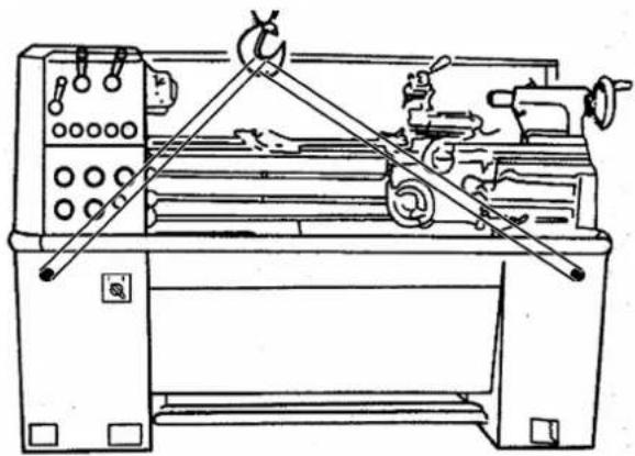
natural_image
Technical line drawing of a lathe machine with levers and control panel (no text or labels)natural_image
Close-up of a mechanical assembly with a red circle highlighting a component (no visible text or symbols)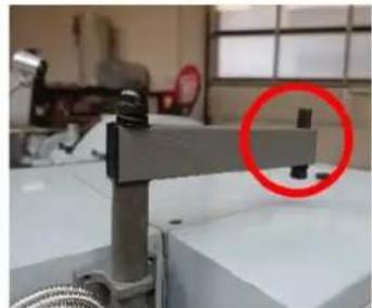
natural_image
Industrial machine with a red circle highlighting a component, no visible text or symbols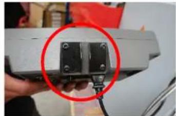
natural_image
Close-up of a hand holding a small black mechanical component with a red circle highlighting it, against a blurred background (no text or symbols visible)
natural_image
Close-up of a mechanical component with a red circle highlighting a specific part (no visible text or symbols)
natural_image
Close-up of a metallic connector with multiple connectors and metal bands, labeled 'X', 'Y', 'Z' (no additional text or symbols visible)Montáž DRO
natural_image
Laboratory setup with mechanical components and a red circle highlighting a specific part (no visible text or symbols)natural_image
Technical line drawing of a mechanical device with a red circle highlighting a component (no text or symbols present)natural_image
Close-up of a circular mechanical component with red curved arrows indicating rotational motion (no text or symbols)natural_image
Close-up of a circular mechanical component with a square hole and a red circle highlighting a feature, placed on a metallic surface (no text or symbols visible)natural_image
Close-up of a metallic mechanical component with a central hole and red measurement lines (no text or symbols visible)natural_image
Close-up of a metallic mechanical component with a conical tip, mounted on a white surface (no visible text or symbols)text_image
J 1 A 6 inch 150mm B PIN K Jnatural_image
Technical line drawing of a mechanical assembly with no visible text or symbolsRegulační šrouby
natural_image
Close-up of a mechanical component with a highlighted circular feature (labeled '1') and an arrow pointing to it, no readable text or symbols present.natural_image
Close-up of a mechanical device with labeled component '3' and a red circle highlighting a circular feature (no readable text or symbols)natural_image
Close-up of a gray panel with four red-circled mounting holes (no text or symbols visible)natural_image
3D diagram of a red cable or wire inside a white enclosure, with no visible text or symbolsnatural_image
Close-up of a mechanical assembly with a red knob and yellow arrow pointing to it, no visible text or symbols.text_image
Labeled mechanical assembly diagram showing components 1, 2, and 3 with directional arrowstext_image
A B C D E F G H Inatural_image
Close-up of a mechanical component with a red arrow indicating a force or direction, no visible text or symbols.natural_image
Pure mechanical diagram showing a cylindrical component intersecting a rectangular block, with no text or symbols present.natural_image
Mechanical component with a lever and handle, no visible text or symbolsnatural_image
Industrial mechanical assembly with white components and red background (no visible text or symbols)natural_image
Close-up of a mechanical device with labeled components (1, 2), no readable text or symbols beyond labelstext_image
Technical diagram of a mechanical device with labeled parts and directional arrows indicating motion or movement.text_image
Technical diagram of a mechanical assembly with numbered components and directional arrows indicating motion or flow.natural_image
Two abstract mechanical or architectural diagrams with no visible text, numbers, or symbols.natural_image
Two abstract geometric diagrams with interlocking shapes and color blocks (no text or symbols)natural_image
Abstract geometric diagram with concentric circles and radial segments, no text or symbols presentnatural_image
Close-up of a mechanical assembly with red arrows pointing to specific components (no visible text or symbols)natural_image
Close-up of a mechanical component with a highlighted circular feature (labeled '1') and an arrow pointing to it, no readable text or symbols present.
text_image
2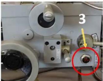
natural_image
Close-up of a mechanical device with labeled components and a red circle highlighting a specific part (no readable text or symbols)natural_image
Technical line drawing of a lathe machine with gauges and levers (no text or labels)text_image
Technical diagram showing mechanical components with numbered annotations and red circular markers indicating featurestext_image
Diagram showing two steps of inserting a CD into a drive, with numbered labels indicating component identification.(EN) With original HOLZMANN spare parts you use parts that are attuned to each other shorten the installation time and elongate your products lifespan.
NOTE

The installation of parts other than original spare parts leads to the loss of the guarantee! Therefore: When replacing components/parts, only use spare parts recommended by the manufacturer.
Order the spare parts directly on our homepage – category SPARE PARTS or contact our customer service
• via our Homepage – category SERVICE - SPARE PARTS REQUEST,
• by e-mail to service@holzmann-maschinen.at.
Always state the machine type, spare part number and designation. To prevent misunderstandings, we recommend that you add a copy of the spare parts drawing with the spare parts order, on which the required spare parts are clearly marked, especially when not using the online-spare-part catalogue.
text_image
Exploded view diagram of a mechanical assembly with numbered parts for identification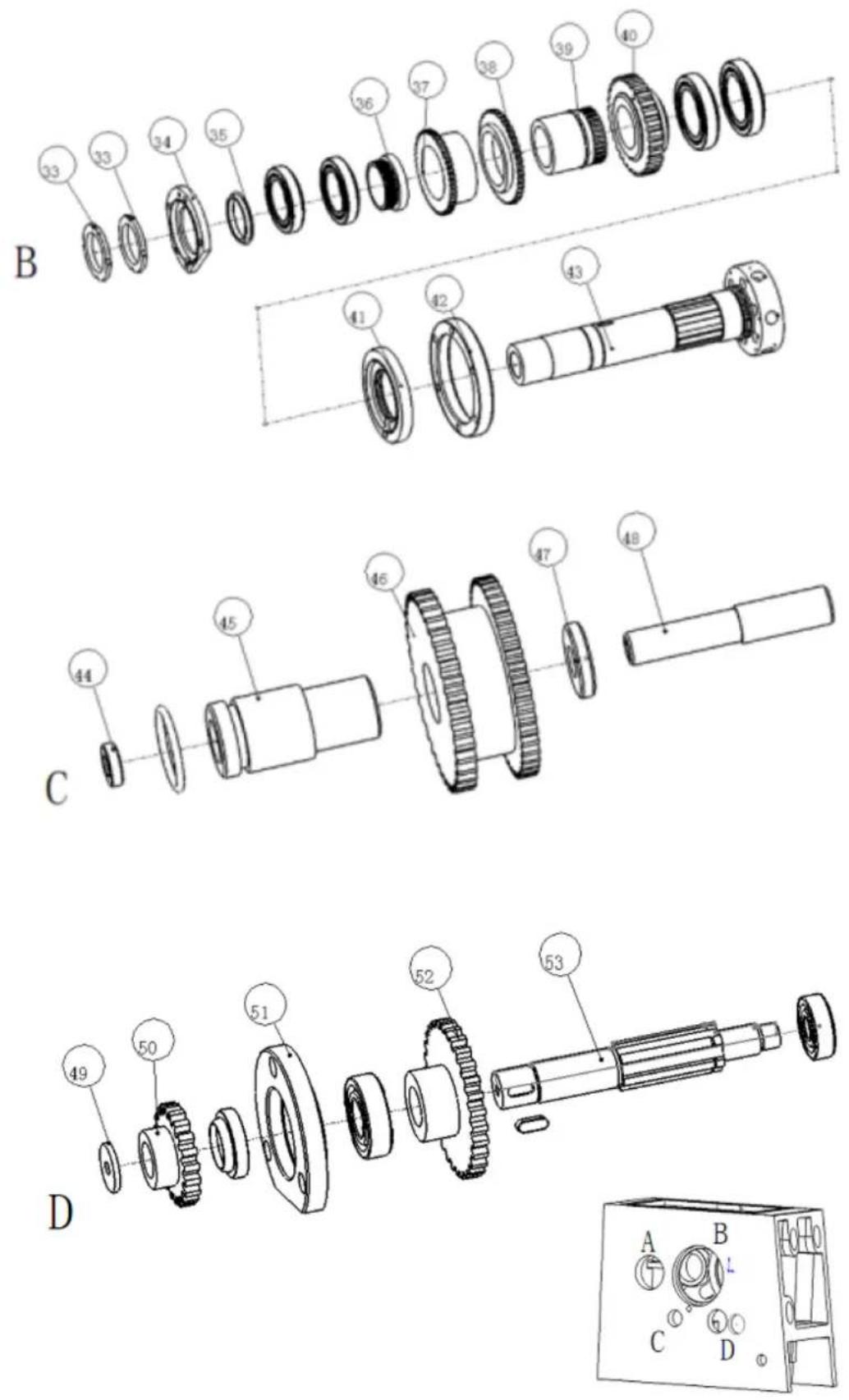
| Part no | NAME | Spec | Qty | Part no | NAME | Spec | Qty |
| 1 Headstock | 1 28 | Gear A 1 | |||||
| 2 Casting cover | 1 29 | Shaft | A 1 | ||||
| 3 Short shaft | 1 30 | Gearset collar | A 1 | ||||
| 4 | Length shaft | 1 | 31 | Ring | A | 1 | |
| 5 Front plug | 1 | 32 | front plug | A | 1 | ||
| 6 Shift lever | 1 | 33 | Nut | B | 1 | ||
| 7 Fork Arm | 1 | 34 | Gasket | B | 1 | ||
| 8 | Length shaft washer | 1 | 35 | Seal pipe | B | 1 | |
| 9 Front plug | 1 36 | Gears | B 1 | ||||
| 10 | Shift fork | 1 37 | Gear | B 1 | |||
| 11 | Shaft | 1 | 38 | Gears | B | 1 | |
| 12 | Fork Arm | 1 | 39 | Gearset | B | 1 | |
| 13 | Big knob | 1 40 | Gear B | 1 | |||
| 14 | Bolt | 1 | 41 | Flange | B | 1 | |
| 15 | Handle | 1 | 42 | Flange | B | 1 | |
| 16 | Pin | 1 | 43 | Splindle | B | 1 | |
| 17 | Shaft sheath | 1 | 44 | Shaft washer | C | 1 | |
| 18 | Gasket | 1 | 45 | Shaft collar | C | 1 | |
| 19 | Handle | 1 | 46 | Gearset | C | 1 | |
| 20 | Oil plug | 1 47 | Shaft washer C 1 | ||||
| 21 | Collar | 1 | 48 | Shaft | C | 1 | |
| 22 | Spring | 1 | 49 | Washer | D | 1 | |
| 23 | Bolt | 1 | 50 | Gear | D | 1 | |
| 24 | Smallness knob | 1 | 51 | Flange | D | 1 | |
| 25 | Shift lever | 1 | 52 shaft gear D | ||||
| 26 | Spindle pulley | A | 1 | 53 | Shaft | D | 1 |
| 27 | Fange | A | 1 | ||||
Cabinet stand assembly
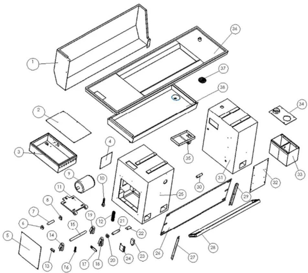
text_image
Exploded view diagram of a device with numbered components for identification| Part no | NAME | Spec | Qty | Part no | NAME | Spec | Qty |
| 1 | chip guard | 1 | 20 | cam | 1 | ||
| 2 cover 1 21 left footplate shaft | |||||||
| 3 | electrical box | 1 | 22 | calipers board | 1 | ||
| 4 | cover | 1 | 23 | switch board | 1 | ||
| 5 | cover | 1 | 24 | journey switch washer | 1 | ||
| 6 | gangway seatd | 1 | 25 | front stand | 1 | ||
| 7 | pin | 1 | 26 | back plate | 1 | ||
| 8 | gangway seat | 1 | 27 | left bracket | 1 | ||
| 9 | motor | 1 | 28 | stand footplate | 1 | ||
| 10 | screw | 1 | 29 | right bracket | 1 | ||
| 11 | motor trestle | 1 | 30 | right footplate shaft | 1 | ||
| 12 | spring | 1 | 31 | back stand | 1 | ||
| 13 | bump board | 1 | 32 | back stand cover | 1 | ||
| 14 | jointing kickstand | 1 | 33 | water tank | 1 | ||
| 15 | gemel shaft | 1 | 34 | water tank cover | 1 | ||
| 16 | bump post | 1 | 35 | funnel | 1 | ||
| 17 | drawbar | 1 | 36 | oil pan | 1 | ||
| 18 | jointing kickstand | 1 | 37 | drawer strainer | 1 | ||
| 19 | jointing kickstand | 1 | 38 | drawer | 1 |
Bed way and rack assembly
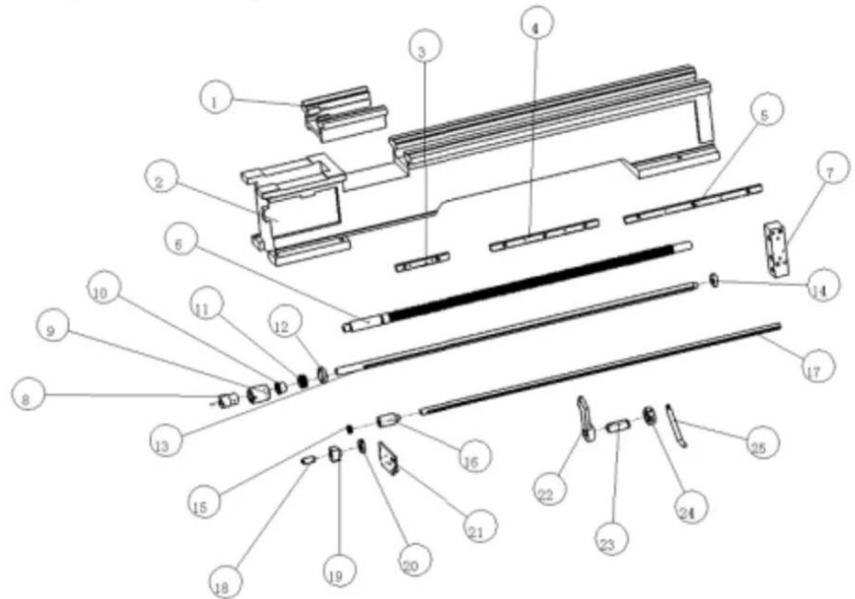
text_image
Exploded view diagram of a mechanical assembly with numbered components for identification| Part no | NAME | Spec | Qty | Part no | NAME | Spec | Qty |
| 1 | bed gap | 1 | 14 | bushing | 1 | ||
| 2 | bed | 1 | 15 | cam | 1 | ||
| 3 | rack gear | 1 | 16 | connect bushing | 1 | ||
| 4 | rack gear | 1 | 17 | feed rod | 1 | ||
| 5 | rack gear | 1 | 18 | shaft | 1 | ||
| 6 | guide screw | 1 | 19 | switch seatd | 1 | ||
| 7 | bracket | 1 | 20 | on-off | 1 | ||
| 8 | connect bushing | 1 | 21 | cover | 1 | ||
| 9 | clutch cover | 1 | 22 | bracket | 1 | ||
| 10 | combine cover | 1 | 23 | steer bushing | 1 | ||
| 11 | spring | 1 | 24 | steer loop | 1 | ||
| 12 | nut | 1 | 25 | steer handle | 1 | ||
| 13 | rod | 1 |
Tool post assembly
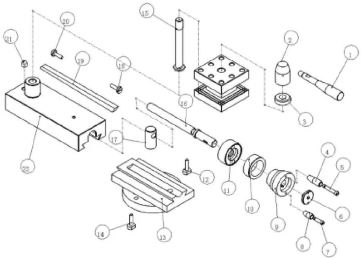
text_image
Exploded view diagram of a mechanical assembly with numbered parts for identification| Part no | NAME | Spec | Qty | Part no | NAME | Spec | Qty |
| 1 | handle | 1 | 12 | screw | 1 | ||
| 2 | handle base | 1 | 13 | swivel base | 1 | ||
| 3 | collar | 1 | 14 | screw | 1 | ||
| 4 | lever | 1 | 15 | shaft | 1 | ||
| 5 | handle | 1 | 16 | guide screw | 1 | ||
| 6 | washer | 1 | 17 | nut | 1 | ||
| 7 | handle | 1 | 18 | screw | 1 | ||
| 8 | lever | 1 | 19 | gib | 1 | ||
| 9 | hand wheel | 1 | 20 | screw | 1 | ||
| 10 | index ring | 1 | 21 | ratch | 1 | ||
| 11 | bracket | 1 | 22 | top slide | 1 |
Saddle assembly
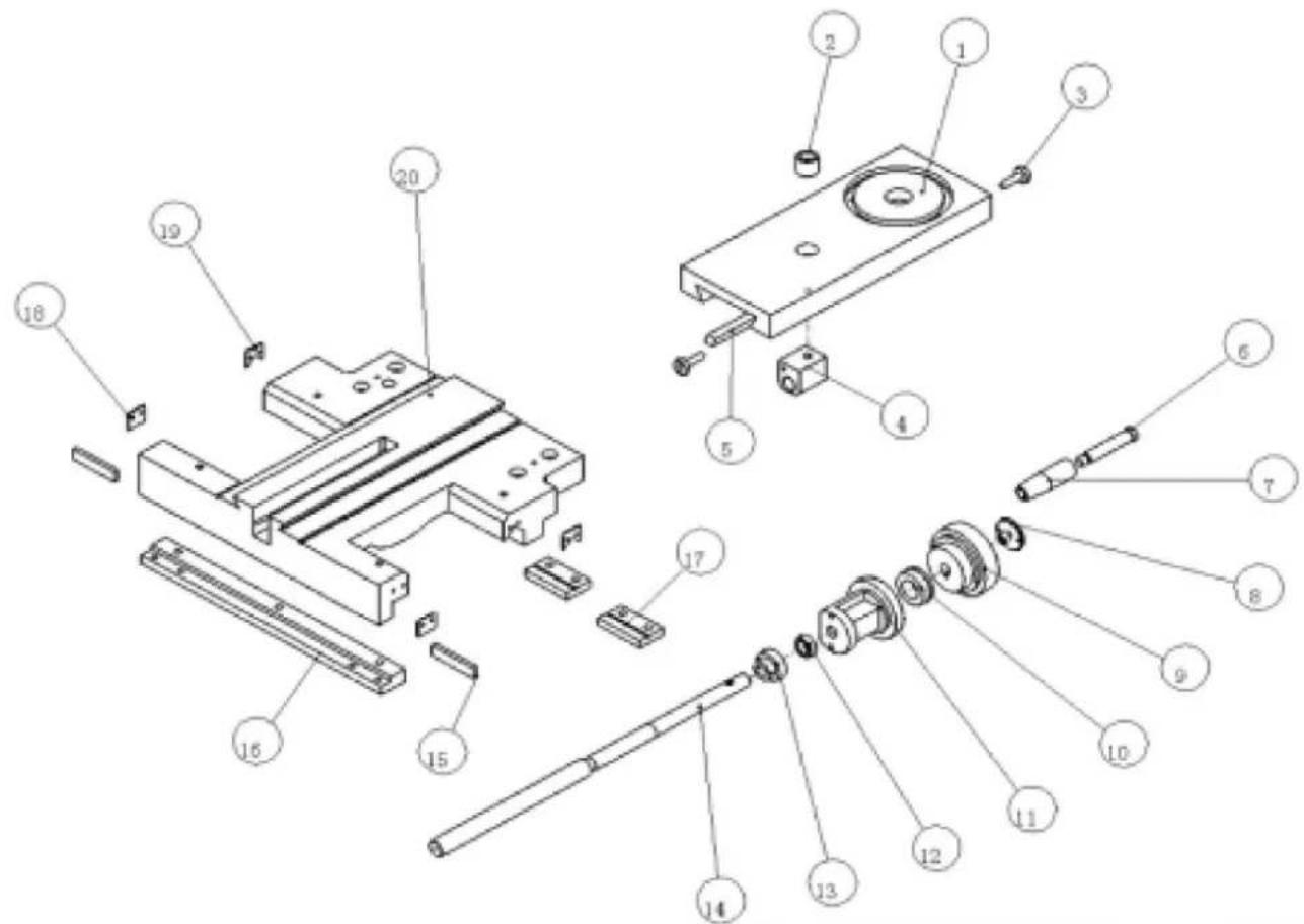
text_image
Exploded view diagram of a mechanical assembly with numbered parts for identification| Part no | NAME | Spec | Qty | Part no | NAME | Spec | Qty |
| 1 | cross slide | 1 | 11 | bracket | 1 | ||
| 2 | bushing | 1 | 12 | washer | 1 | ||
| 3 | screw | 1 | 13 | gears | 1 | ||
| 4 | nut | 1 | 14 | guide screw | 1 | ||
| 5 | gib | 1 | 15 | redressal plate | 1 | ||
| 6 | handle | 1 | 16 | back press plate | 1 | ||
| 7 | handle knot | 1 | 17 | front press plate | 1 | ||
| 8 | washer | 1 | 18 | wiper | 1 | ||
| 9 | hand wheel | 1 | 19 | wiper | 1 | ||
| 10 | index ring | 1 | 20 | saddle | 1 |
Change gear assembly
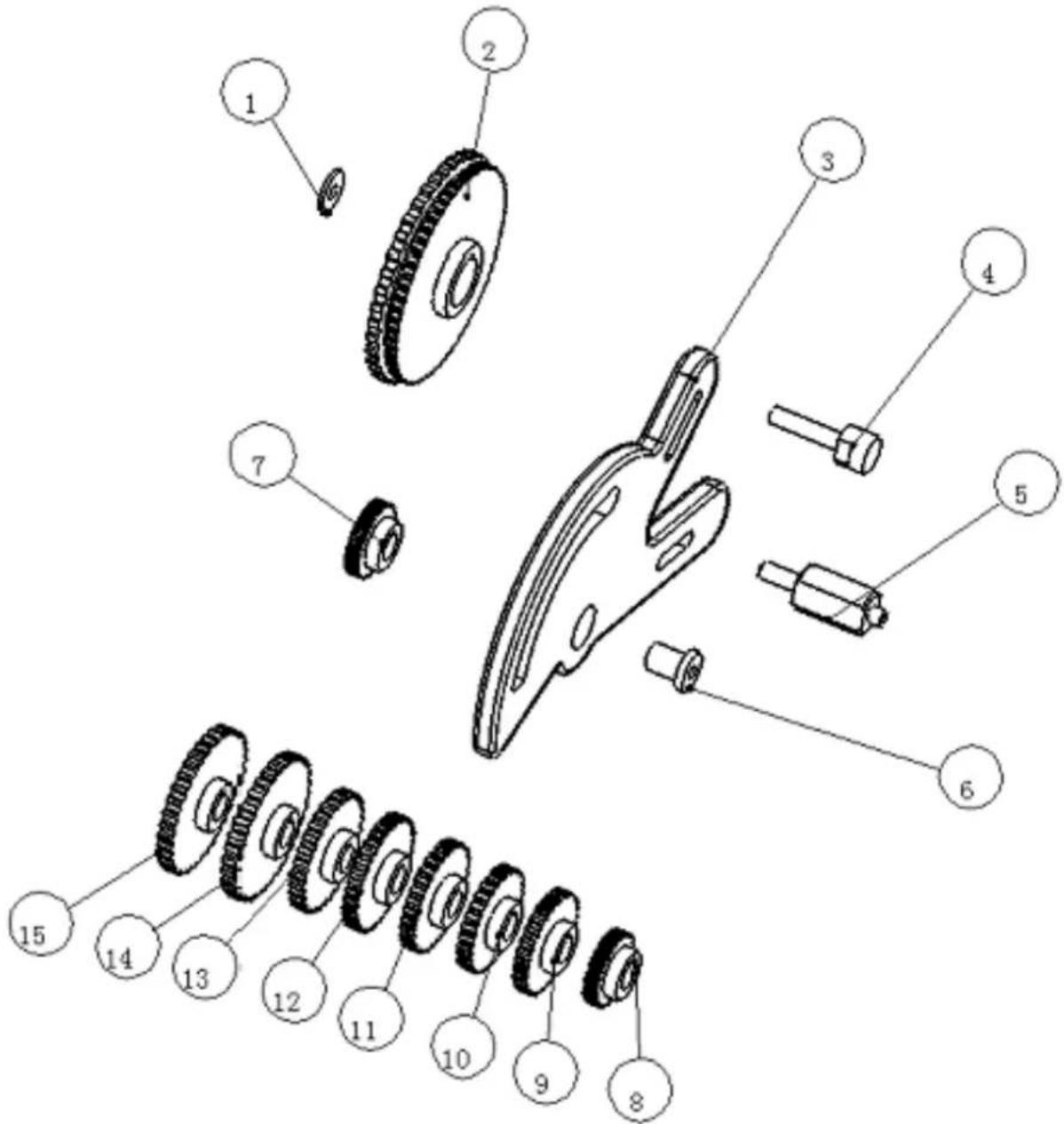
text_image
Exploded view diagram of a mechanical assembly with numbered parts for identification| Part no | NAME | Spec | Qty | Part no | NAME | Spec | Qty |
| 1 | washer | 1 | 9 | change gear | Z56 | 1 | |
| 2 | gear | M1.25 Z120/Z127 | 1 | 10 | change gear | Z57 | 1 |
| 3 | bracket | 1 | 11 | change gear | Z60 | 1 | |
| 4 | shaft | 1 | 12 | change gear | Z63 | 1 | |
| 5 | screw | 1 | 13 | change gear | Z66 | 1 | |
| 6 | collar | 1 | 14 | change gear | Z78 | 1 | |
| 7 | change gear | Z40 | 1 | 15 | change gear | Z80 | 1 |
| 8 | change gear | Z54 | 1 | ||||
Apron assembly
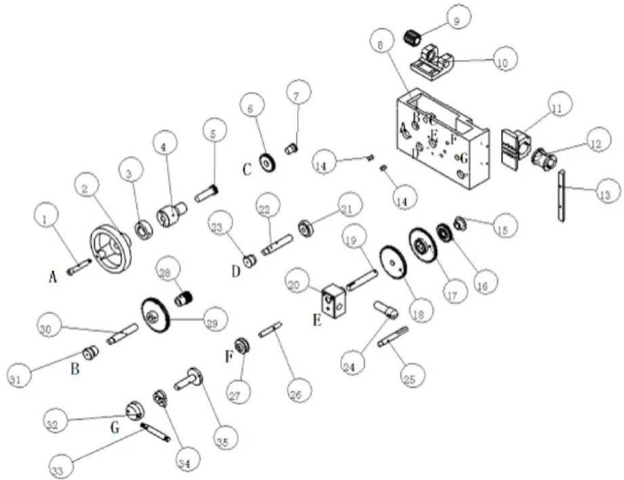
text_image
Exploded view diagram of a mechanical assembly with numbered components and labeled parts A through G| Part no | NAME | Spec | Qty | Part no | NAME | Spec | Qty |
| 1 | handle | A | 1 | 19 | shaft | E | 1 |
| 2 | hand wheel | A | 1 | 20 | boss | E | 1 |
| 3 | index ring | A | 1 | 21 | bushing | D | 1 |
| 4 | bracket | A | 1 | 22 | shaft | D | 1 |
| 5 | gear shaft | A | 1 | 23 | bushing | D | 1 |
| 6 | gear | M2/Z25 | 1 | 24 | gear shift lever | 1 | |
| 7 | shaft | C | 1 | 25 | handle | 1 | |
| 8 | apron case | 1 | 26 | shaft | F | 1 | |
| 9 | worm | 1 | 27 | safety shifter | F | 1 | |
| 10 | worm amelia | 1 | 28 | gear | M2/Z14 | 1 | |
| 11 | nut seat | 1 | 29 | big gear | M2/Z50 | 1 | |
| 12 | half nut | 1 | 30 | shaft | B | 1 | |
| 13 | gib | 1 | 31 | bushing | B | 1 | |
| 14 | keep off | 1 | 32 | handle wheel | G | 1 | |
| 15 | bushing | E | 1 | 33 | handle | G | 1 |
| 16 gear | M2/Z25 | 1 | 34 | cam | G | 1 | |
| 17 | big gear | M2/Z52 | 1 | 35 | wheel shaft | G | 1 |
| 18 | gear | M2/Z48 | 1 | ||||
text_image
Exploded view diagram of a mechanical assembly with numbered parts for identification| Part no | NAME | Spec | Qty | Part no | NAME | Spec | Qty |
| 1 | handle | 1 | 10 | guide pin | 1 | ||
| 2 | screw | 1 | 11 | guide screw | 1 | ||
| 3 | shaft | 1 | 12 | pressing collar | 1 | ||
| 4 | press ring plate | 1 | 13 | flange | 1 | ||
| 5 | base | 1 | 14 | index ring | 1 | ||
| 6 | handle | 2 | 1 | 15 | tall stock body | 1 | |
| 7 | screw | 2 | 1 | 16 | handwheel | 1 | |
| 8 | shaft | 2 | 1 | 17 | handwheel knot | 1 | |
| 9 | sleeve | 1 | 18 | insurance screw | 1 |
Feed box assembly
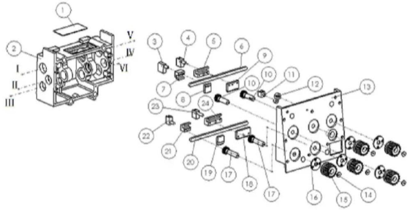
text_image
Technical diagram of an electronic device with numbered components and labeled sections I, II, III, IV, V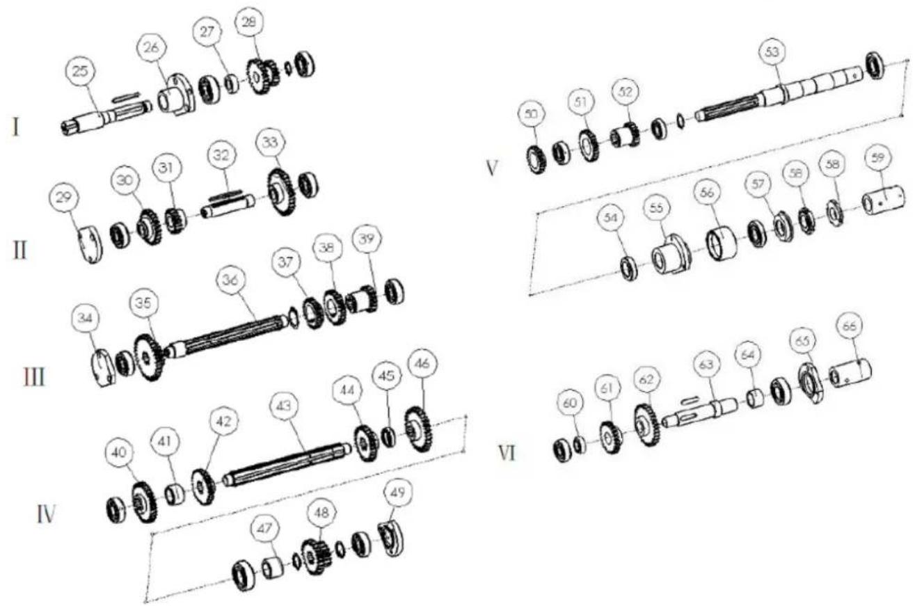
text_image
I 25 26 27 28 29 29 30 31 32 33 Ⅱ 34 35 36 37 38 39 Ⅲ 40 41 42 43 44 45 46 Ⅳ 47 48 49 V 50 51 52 53 54 55 56 57 58 59 VI 60 61 62 63 64 65 66| Part no | NAME | Spec | Qty | Part no | NAME | Spec | Qty |
| 1 | oil cover | 1 | 34 | bearing cover | 1 | ||
| 2 | gear box | 1 | 35 | gear | III 1 | 1 | |
| 3 | shift fork | 1# | 1 | 36 | shaft | III | 1 |
| 4 | shift fork | 2# | 1 | 37 | gear | III 4 | 1 |
| 5 | slide dollop | 2# | 1 | 38 | gear | III 3 | 1 |
| 6 | guide pole | 1 | 39 | gear | III 2 | 1 | |
| 7 | slide dollop | 1# | 1 | 40 | gear | IV 1 | 1 |
| 8 | gear rack | 1# | 1 | 41 | washer | IV 2 | 1 |
| 9 | gear rack | 2# | 1 | 42 | gear | IV 3 | 1 |
| 10 | gear shaft | 1 | 43 | shaft | IV | 1 | |
| 11 | shift lever | 1 | 44 | gear | IV 4 | 1 | |
| 12 | fork arm | 1 | 45 | washer | 2 | 1 | |
| 13 | gear box cover | 1 | 46 | gear | IV 5 | 1 | |
| 14 | washer | 1 | 47 | washer | 3 | 1 | |
| 15 | knob | 1 | 48 | gearset | IV 8 | 1 | |
| 16 | flange | 1 | 49 | bearing cover | 1 | ||
| 17 | gear shaft | 2 | 50 | gear | III 4 | 1 | |
| 18 | gear rack | 4# | 1 | 51 | gear | III 3 | 1 |
| 19 | gear rack | 3# | 1 | 52 | gear | III 2 | 1 |
| 20 | guide pole | 1 | 53 | shaft | V | 1 | |
| 21 | slide dollop | 3# | 1 | 54 | washer | V 1 | 1 |
| 22 | shift fork | 3# | 1 | 55 | separator | V | 1 |
| 23 | shift fork | 4# | 1 | 56 | dustproof loop | V 2 | 1 |
| 24 | slide dollop | 4# | 1 | 57 | washer | V 3 | 1 |
| 25 | input shaft | 1 | 1 | 58 | round nut | V 4 | 1 |
| 26 | flange | 1 | 1 | 59 | collar | V 5 | 1 |
| 27 | collapsible | 1 | 1 | 60 | washer | VI 1 | 1 |
| 28 | gear | 1 | 1 | 61 | gear | VI 2 | 1 |
| 29 | bearing cover | 1 | 62 | gearset | VI 3 | 1 | |
| 30 | gear | II 1 | 1 | 63 | shaft | VI | 1 |
| 31 | gear | II 2 | 1 | 64 | spacing loop | VI 4 | 1 |
| 32 | shaft | II | 1 | 65 | bearing cover | 1 | |
| 33 | gear | II 3 | 1 | 66 | collar | VI | 1 |
Stead assembly
| Part no | NAME | Spec | Qty |
| 1 | chuck cover | 1 | |
| 2 | shaft 1 | ||
| 3 | switch box | 1 |
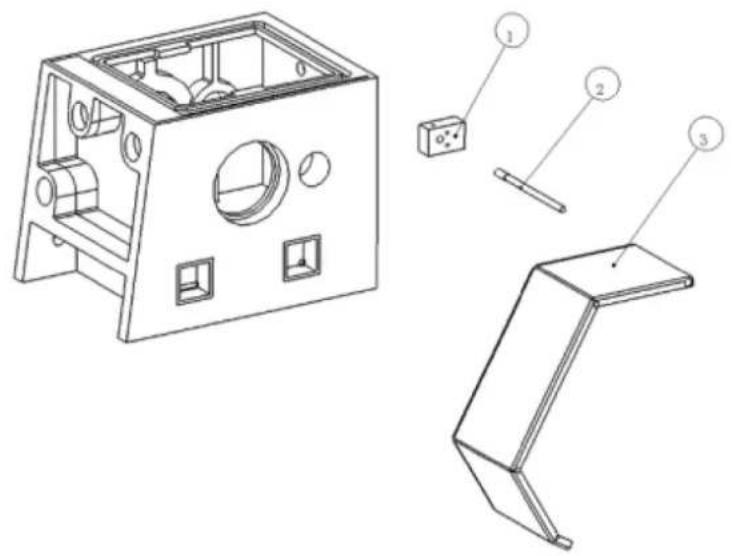
text_image
Technical diagram of a mechanical housing with labeled components including panel, socket, and bracket partsChasing dial
| Part no | NAME | Spec | Qty |
| 1 | housing | 1 | |
| 2 thread dial | 1 | ||
| 3 | gear | Z16 | 1 |
| 4 washer | 1 | ||
| 5 gear | Z15 | 1 | |
| 6 gear | Z14 | 1 |
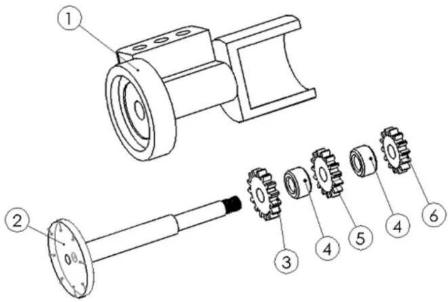
text_image
Technical diagram of a mechanical assembly with numbered parts for identificationFollow rest assembly
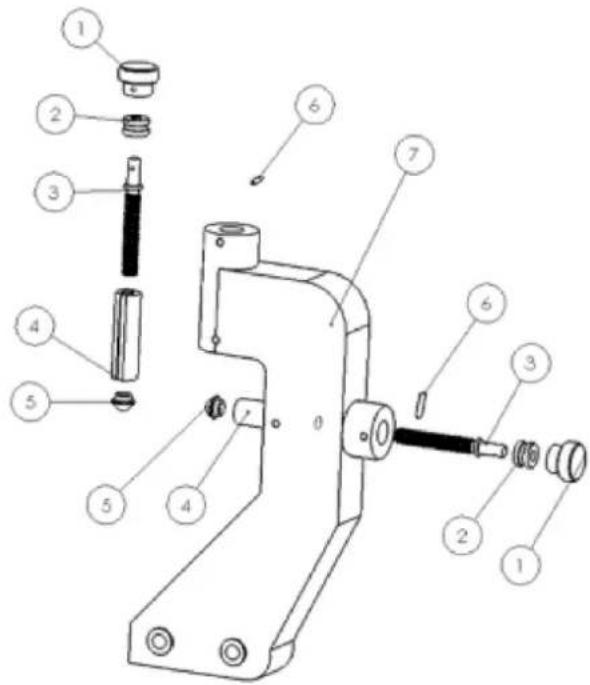
text_image
Technical diagram of a mechanical device with numbered parts for identification| Part no | NAME | Spec | Qty |
| 1 | bakelite knob | 1 | |
| 2 collar | 1 | ||
| 3 | guide screw | 1 | |
| 4 pressing collar | 1 | ||
| 5 | pressing base | 1 | |
| 6 | column pin | 1 | |
| 7 | body | 1 |
Steady rest assembly
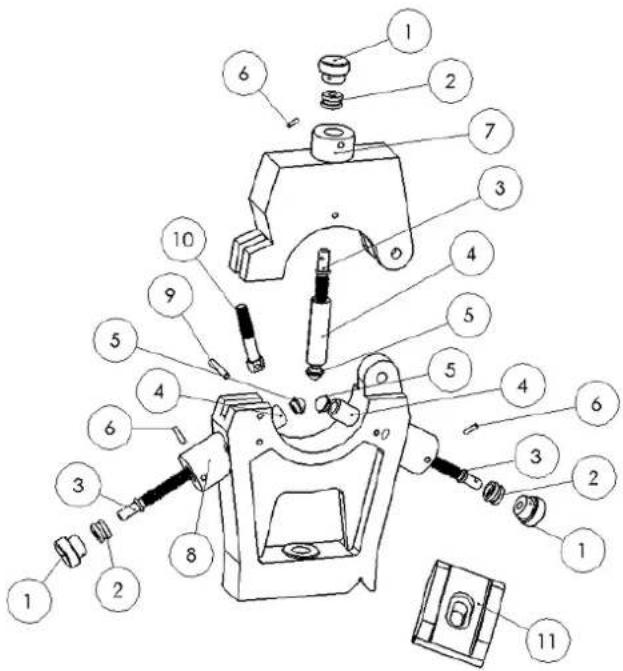
text_image
Exploded view diagram of a mechanical assembly with numbered parts for identification| Part no | NAME | Spec | Qty |
| 1 bakelite handle | 1 | ||
| 2 collar | 1 | ||
| 3 pressing lever | 1 | ||
| 4 pressing collar | 1 | ||
| 5 pressing base | 1 | ||
| 6 pin | 1 | ||
| 7 top body | 1 | ||
| 8 base body | 1 | ||
| 9 pin | 1 | ||
| 10 locking screw | 1 | ||
| 11 pressing plate | 1 |
Tool post guard
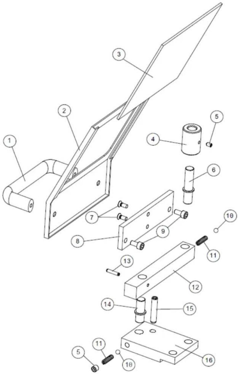
text_image
Technical diagram of a mechanical assembly with numbered components for identification| Part no | NAME | Qty | Part no | NAME | Qty |
| 1 Handle 1 9 Screw 2 | |||||
| 2 | Guard | 1 | 10 | Steel ball | 2 |
| 3 Shield 1 11 Spring 2 | |||||
| 4 | Position sleeve | 1 | 12 | Arm | 1 |
| 5 | Screw | 2 | 13 | Pin | 1 |
| 6 | Position column I | 1 | 14 | Position column II | 1 |
| 7 | Screw | 2 | 15 | Cylindrical pin | 1 |
| 8 | Plate I | 1 | 16 | Plate II | 1 |
For mechanical and electrical components Company HOLZMANN MASCHINEN GmbH grants a warranty period of 2 years for DIY use and a warranty period of 1 year for professional/industrial use - starting with the purchase of the final consumer (invoice date).
In case of defects during this period which are not excluded by paragraph 3, Holzmann will repair or replace the machine at its own discretion.
2.) Report
In order to check the legitimacy of warranty claims, the final consumer must contact his dealer. The dealer has to report in written form the occurred defect to HOLZMANN MASCHINEN GmbH. If the warranty claim is legitimate, HOLZMANN MASCHINEN GmbH will pick up the defective machine from the dealer. Return shipments by dealers which have not been coordinated with HOLZMANN MASCHINEN GmbH will not be accepted. A RMA number is an absolute must-have for us - we won't accept returned goods without an RMA number!
3.) Regulations
a) Warranty claims will only be accepted when a copy of the original invoice or cash voucher from the trading partner of HOLZMANN MASCHINEN GmbH is enclosed to the machine. The warranty claim expires if the accessories belonging to the machine are missing.
b) The warranty does not include free checking, maintenance, inspection or service works on the machine. Defects due to incorrect usage through the final consumer or his dealer will not be accepted as warranty claims either.
c) Excluded are defects on wearing parts such as carbon brushes, fangers, knives, rollers, cutting plates, cutting devices, guides, couplings, seals, impellers, blades, hydraulic oils, oil filters, sliding jaws, switches, belts, etc.
d) Also excluded are damages on the machine caused by incorrect or inappropriate usage, if it was used for a purpose which the machine is not supposed to, ignoring the user manual, force majeure, repairs or technical manipulations by not authorized workshops or by the customer himself, usage of non-original Holzmann spare parts or accessories.
e) After inspection by our qualified staff, resulted costs (like freight charges) and expenses for not legitimated warranty claims will be charged to the final customer or dealer.
f) In case of defective machines outside the warranty period, we will only repair after advance payment or dealer's invoice according to the cost estimate (incl. freight costs) of HOLZMANN MASCHINEN GmbH.
g) Warranty claims can only be granted for customers of an authorized HOLZMANN MASCHINEN GmbH dealer who directly purchased the machine from HOLZMANN MASCHINEN GmbH. These claims are not transferable in case of multiple sales of the machine.
4.) Claims for compensation and other liabilities
The liability of company HOLZMANN MASCHINEN GmbH is limited to the value of goods in all cases.
Claims for compensation because of poor performance, lacks, damages or loss of earnings due to defects during the warranty period will not be accepted.
HOLZMANN MASCHINEN GmbH insists on its right to subsequent improvement of the machine.
SERVICE
After Guarantee and warranty expiration specialist repair shops can perform maintenance and repair jobs. But we are still at your service as well with spare parts and/or product service. Place your spare part/repair service cost inquiry by
• Mail to service@holzmann-maschinen.at.
• Or use the online complaint order formula provided on our homepage – category service
60 DÉCLARATION DE GARANTIE (FR)
1.) Garantie
(EN) We monitor the quality of our delivered products in the frame of a Quality Management policy.
Your opinion is essential for further product development and product choice. Please let us know about your:
- Impressions and suggestions for improvement.
- Experiences that may be useful for other users and for product design
- Experiences with malfunctions that occur in specific operation modes
We would like to ask you to note down your experiences and observations and send them to us via E-mail or by post: