D 300F - Milling machine Holzmann - Free user manual and instructions
Find the device manual for free D 300F Holzmann in PDF.
User questions about D 300F Holzmann
0 question about this device. Answer the ones you know or ask your own.
Ask a new question about this device
Download the instructions for your Milling machine in PDF format for free! Find your manual D 300F - Holzmann and take your electronic device back in hand. On this page are published all the documents necessary for the use of your device. D 300F by Holzmann.
USER MANUAL D 300F Holzmann
natural_image
Red and gray metalworking machine with attached control panel and mechanical components (no visible text or symbols on the machine body)D 300F
1 INHALT /INDEX
13.1 Intended Use....23
13.2 Security instructions 24
13.3 Remaining risk factors.... 25
14 ASSEMBLY 26
14.1 Preparatory activities 26
14.1.1 Delivery content 26
14.1.2 Workplace requirements....26
14.1.3 Preparation of the surface....26
14.2 Assembly 26
14.2.1 Lock lever....26
14.2.2 Face plate....27
14.2.3 Spur center....27
15 OPERATION 28
15.1 Operation instructions.... 28
15.2Operation 29
15.2.1 Tailstock adjustment....29
15.2.2 Tool rest adjustment....29
15.2.3 On-Off-switch....29
15.2.1 Speed adjustment....29
16 MAINTENANCE 30
16.1 Maintenance plan .... 30
16.2 Cleaning 30
16.3 Disposal.... 31
17 TROUBLE SHOOTING 31
18 PREFACIO (ES) 32
19 CARACTERÍSTICAS TÉCNICAS 33
19.1 Controles y componentes .... 33
19.2 Datos técnicos 33
20 SEGURIDAD 34
EN EC-CONFORM: This product complies with EC-directives
EN READ THE MANUAL! Read the user and maintenance manual carefully and get familiar with the controls in order to use the machine correctly and to avoid injuries and machine defects.
EN ATTENTION! Ignoring the safety signs and warnings applied on the machine as well as ignoring the security and operating instructions can cause serious injuries and even lead to death.
EN Protective clothing!
ES iProtección
FR Protection
EN Stop and pull out the power plug before any break and engine maintenance!
EN Operation with gloves forbidden!
EN Warning against thrown-off items!

EN Hand injuries because of belt drive!
text_image
Technical diagram of a mechanical device with numbered components labeled 1, 2, and 37.3.3 Mitnehmer
natural_image
Technical line drawing of a mechanical device with a spring and connector (no text or symbols)natural_image
Technical line drawing of a mechanical device with a numbered component (no text or symbols)natural_image
Technical line drawing of a mechanical assembly with a tool and component (no text or symbols)8 BETRIEB
text_image
Technical diagram of a mechanical device with numbered parts labeled 1 through 6text_image
Technical diagram of a mechanical assembly with numbered components for identification
HINWEI S
This manual contains information and important instructions for the installation and correct use of the wood lathe D 300F.
Following the usual commercial name of the device (see cover) is substituted in this manual with the name "machine".
This manual is part of the product and shall not be stored separately from the product. Save it for later reference and if you let other people use the product, add this instruction manual to the product.

Please read and obey the security instructions!
Before first use read this manual carefully. It eases the correct use of the product and prevents misunderstanding and damages of product and the user's health.
Due to constant advancements in product design, construction pictures and content may diverse slightly. However, if you discover any errors, inform us please.
Technical specifications are subject to changes!
Please check the product contents immediately after receipt for any eventual transport damage or missing parts.
Claims from transport damage or missing parts must be placed immediately after initial product receipt and unpacking before putting the product into operation.
Please understand that later claims cannot be accepted anymore.
Copyright
© 2016
This document is protected by international copyright law. Any unauthorized duplication, translation or use of pictures, illustrations or text of this manual will be pursued by law. Court of jurisdiction is the Landesgericht Linz or the competent court for 4170 Haslach, Austria!
Customer service contact
| No. | Specification | No. | Specification |
| 1 | Headstock | 7 | Spur center |
| 2 | Faceplate | 8 | Motor |
| 3 | Tool rest | 9 | Speed controller |
| 4 | Tailstock | 10 | Excentric axis |
| 5 | On-Off switch | 11 | Machine bed |
| 6 | Circuit break button | 12 | Excentric axis and handle tailstock |
12.2 Technical details
| Spezification | D 300F |
| Voltage | 230V / 50Hz |
| Motor power | 250W |
| Spindle speed | 750-3200min ^-1 |
| Distance between centers | 305mm |
| Center height above machine bed | 110mm |
| Head stock, norm spindle | M33 DIN800 |
| Morse taper | MT1 |
| Tail spindle travel | 35mm |
| Dimensions | 810 x 360 x 300mm |
| Weight | 20kg |
13 SAFETY
13.1 Intended Use
The machine must only be used for its intended purpose! Any other use is deemed to be a case of misuse.
To use the machine properly you must also observe and follow all safety regulations, the assembly instructions, operating and maintenance instructions lay down in this manual.
All people who use and service the machine have to be acquainted with this manual and must be informed about the machine's potential hazards.
It is also imperative to observe the accident prevention regulations in force in your area.
The same applies for the general rules of occupational health and safety.
The machine is used for:
Turning wood.
Any manipulation of the machine or its parts is a misuse, in this case HOLZMANN-MASCHINEN and its sales partners cannot be made liable for ANY direct or indirect damage.
Even when the machine is used as prescribed it is still impossible to eliminate certain residual risk factors.

WARNING
- Use the machine never with defective or without mounted guard!
- The removal or modification of the safety components may result in damage to equipment and serious injury!
HIGHEST RISK OF INJURY!
Ambient conditions
The machine may be operated:
humidity
max. 70%
temperature
+5°C to +40°C (+41°F to +104°F)
The machine shall not be operated outdoors or in wet or damp areas.
The machine shall not be operated in areas exposed to increased fire or explosion hazard.
Prohibited use
- The operation of the machine outside the stated technical limits described in this manual is forbidden.
- Operation of the machine function without emergency stop button or impeller box with open doors is prohibited.
• The use of the machine not according with the required dimensions is forbidden.
- The use of the machine not being suitable for the use of the machine and not being certified is forbidden.
• Any manipulation of the machine and parts is forbidden.
- The use of the machine for any purposes other than described in this user-manual is forbidden.
• The unattended operation on the machine during the working process is forbidden!
• It is not allowed to leave the immediate work area during the work is being performed.
13.2 Security instructions
Missing or non-readable security stickers have to be replaced immediately!
The locally applicable laws and regulations may specify the minimum age of the operator and limit the use of this machine!
To avoid malfunction, machine defects and injuries, read the following security instructions

- Keep your work area dry and tidy! An untidy work area may cause accidents. Avoid slippery floor.
• Make sure the work area is lighted sufficiently - Install the machine so that there is sufficient space for safe operation and workpiece handling

- Do not overload the machine
- Provide good stability and keep balance all times
- Avoid abnormal working postures! Make sure you stand squarely and keep balance at all times.
- Always stay focused when working. Reduce distortion sources in your working environment. The operation of the machine when being tired, as well as under the influence of alcohol, drugs or concentration influencing medicaments is forbidden.

- Do not climb onto the machine!
- The machine must be operated only by trained persons (knowledge and understanding of this manual), which have no limitations of motor skills compared with conventional workers..

- Do not allow other people, particularly children, to touch the machine or the cable. Keep them away from your work area.
• Make your workshop childproof.
- Make sure there is nobody present in the dangerous area. The minimum safety distance is 2m
- Wear suitable work clothes! Do not wear loose clothing or jewelry as they might get caught in moving parts and cause severe accidents! Wear a hair net if you have long hair.
- Loose objects can become entangled and cause serious injuries!
- Use personal safety equipment: ear protectors and safety goggles when working with the machine.
- Do not wear safety gloves!
- Never leave the machine running unattended! Before leaving the working area switch the machine off and wait until the machine stops.
- Always disconnect the machine prior to any actions performed at the machine.
- Avoid unintentional starting
- Do not use the machine with damaged switch
- The plug of an electrical tool must strictly correspond to the socket. Do not use any adapters together with earthed electric tools
- Each time you work with an electrically operated machine, caution is advised! There is a risk of electric shock, fire, cutting injury;
- Protect the machine from dampness (causing a short circuit)
- Use power tools and machines never in the vicinity of flammable liquids and gases (danger of explosion)
- Check the cable regularly for damage
- Do not use the cable to carry the machine or to fix the work piece
- Protect the cable from heat, oil and sharp edges
- Avoid body contact with earthed

- Before starting the machine remove any adjusting wrenches and screwdrivers
• Fix the workpiece with the right tool - Machine only stock which is chucked securely on the machine, always check before switching the machine on
- Provide workpiece with centre holes before clamping between centres
- Before start working remove any nails and other foreign bodies from the workpiece
- Keep any machine that is not being used out of reach of children
- Never grab into the running machine!
- Remove chips and workpiece parts only if the machine is standing still!
- Never stop workpieces with the hand during run out!
- Never take measurements on a rotating workpiece!


13.3 Remaining risk factors

WARNING
It is important to ensure that each machine has remaining risks. In the execution of all work (even the simplest) greatest attention is required. A safe working depends on you!
Even if the machine is used as required it is still impossible to eliminate certain residual risk factors totally. The following hazards may arise in connection with the machine's construction and design:
• Risk of injury to the hands / fingers by the rotating workpioece during operation.
- Risk of injury due to sharp edges of the workpiece, especially in non-fixed with a suitable tool / device workpiece.
- Risk of injury: hair and loose clothing, etc. can be captured and wound up! Safety regulations must be observed with regard to clothing.
- Risk of injury due to contacting with live electrical components.
• Risk of injury due to dust emissions, treated with harmful agents workpieces
- Risk of injury to the eye by flying debris, even with safety goggles.
- Risk of injury to the hearing by prolonged labor without hearing protection.
- Risk of injury due to kickback:
Kickback is a sudden reaction. This causes the ejection of the tool to the direction of the operator.
These risk factors can be minimized through obeying all security and operation instructions, proper machine maintenance, proficient and appropriate operation by persons with technical knowledge and experience.
14 ASSEMBLY
14.1 Preparatory activities
14.1.1 Delivery content
Please check the product contents immediately after receipt for any eventual transport damage or missing parts. Claims from transport damage or missing parts must be placed immediately after initial machine receipt and unpacking before putting the machine into operation. Please understand that later claims cannot be accepted anymore.
14.1.2 Workplace requirements
The workplace has to fulfill the requirements.
The ground has to be even, in level and hard. It must be suitable at least to weight it with double weight per square meter than the machines net weight.
The chosen workplace must have access to a suitable electric supply net hat complies with the machines requirements.
14.1.3 Preparation of the surface
Uncoated metal machine parts have been insulated with a greasy layer to inhibit corrosion.
This layer has to be removed. You can use standard solvents that do not damage the machine surface.

NOTICE
Do not use solvents based on nitrite, aggressive solvents like break cleaners or scrubbing agents!
These damage the machine surface.
14.2 Assembly
The machine is delivered pre-assembled.
For transport reasons some parts of the machine can be assembled by the customer.
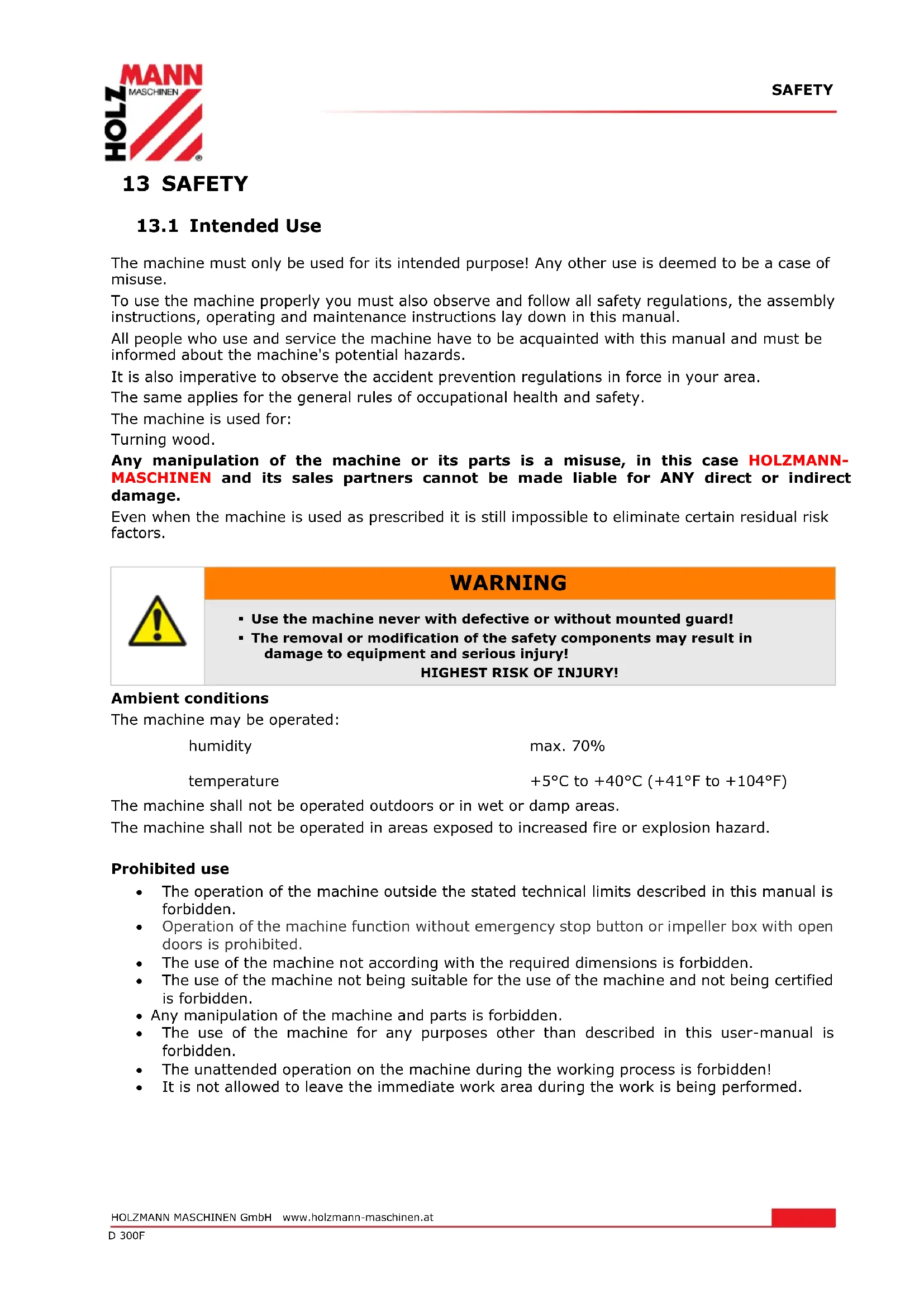
14.2.1 Lock lever
This lever has to be mount at the headstock and the tool rest. The shoulder screw (1) passes through the spring (2) and the handle lever (3). If either lock lever has come loose from the lathe or has come apart in shipping, reassemble it and thread into place.
To operate, push the handle lever in and turn clockwise to tighten. Pulling the handle lever outward will disengage the threaded shaft, allowing you to reposition the lever handle so it is out of the way.
text_image
1 2 314.2.2 Face plate
Thread the faceplate (1) onto the end of the headstock spindle and hand tighten. Place the wrench (2) over the flats on the faceplate. Insert the tip of the push-out rod (3) into one of the slots in the side of the headstock spindle. While gripping the push-out rod firmly, turn the wrench to either tighten or loosen the faceplate. Remove the push-out rod and wrench. If the faceplate is being removed, continue turning it until it comes off the spindle threads.

WARNING
Do not operate the lathe until it is completely assembled and adjusted according to the instructions.
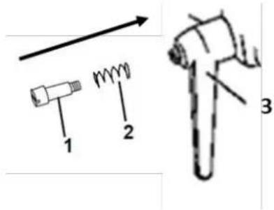
14.2.3 Spur center
Insert the tailstock cup center (1) into the hollow center of the headstock spindle.
Insert the shaft (1) of the tailstock center into the hollow center of the tailstock spindle.
Insert the push-out rod (1) into the far end of the headstock spindle or the tailstock spindle until it comes into contact with the shaft of the spur or center. Tap the end of the push-out rod (1) until the spur or center comes loose.
text_image
Technical diagram of a mechanical device with numbered components labeled 1, 2, and 3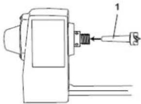
natural_image
Technical line drawing of a mechanical device with a labeled component (no text or symbols present)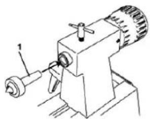
natural_image
Technical line drawing of a mechanical device with a tool and base (no text or symbols)
natural_image
Technical line drawing of a mechanical assembly with a tool and component (no text or symbols)15 OPERATION
Device to be operated in a perfect state only. Inspect the device visually every time it is to be used. Check in particular the safety equipment, electrical controls, electric cables and screwed connection for damage and if tightened properly. Replace any damaged parts before operating the device.
15.1 Operation instructions

WARNING
Perform all machine settings with the machine being disconnected from the power supply!


ATTENTION
Never switch the machine on while pressing the chisel against the material!

NOT ICE
- Before switching the machine on, make sure that the tool rest is firmly tightened
- Rotate the clamped workpiece each time before turning by hand to ensure that it runs freely and does not touch the rest tool!
- Thereby check also whether the workpiece is centred and tighten clamped!
- Make sure to guide and hold the chisel with both hands safe and tight during machining!
• Work only with well sharpened tools!
• Work large and unbalanced workpieces at low spindle speed only! - Specifications regarding the maximum or minimum size of the workpiece must be observed!
• Workpieces with cracks may not be used! - Only process selected woods without defects!
15.2 Operation
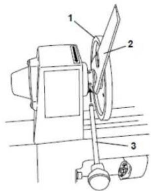
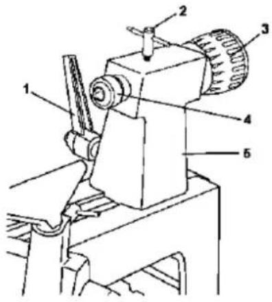
15.2.1 Tailstock adjustment
- Move the tailstock (5) by loosening the lock lever (1) and pushing the tailstock to the desired position on the bed. Lock by tightening the lock lever (1).
- The spindle can extend up to 2 1/2" from the tailstock housing. You can move the tailstock spindle (4) by loosening the spindle lock lever (2) and then turning the hand wheel (3). Turning the hand wheel clockwise extends the spindle; turning it counterclockwise retracts the spindle. Lock the lock levers (1) and the spindle lock levers (2) before operating the lathe.
- The tailstock spindle is hollow and can be accessed from the handwheel end. Use the push-out rod to remove the center cup or to drill holes through the center of a workpiece on a faceplate.
text_image
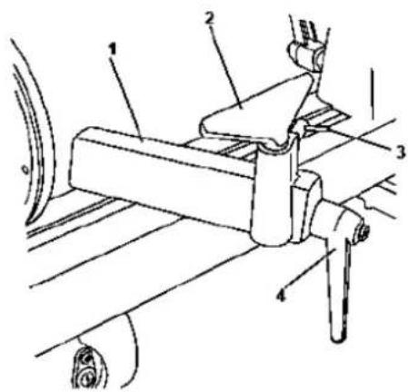
Technical diagram of a mechanical device with numbered parts labeled 1 through 615.2.2 Tool rest adjustment
- To move the tool rest base (1), loosen the lock lever (4) and move the base to the right or left and back or front. Tighten the lever (4) when the tool rest base is in the desired position.
- To adjust the angle of the tool rest (2), loosen the lock lever (3), move the tool rest to the desired position, and tighten the lock lever.
- To change to the other tool rest, loosen the lock lever (3) and pull the tool rest (2) out of the tool rest base, insert the other tool rest, adjust to desired position, and tighten the lock lever (3).

text_image
Technical diagram of a mechanical assembly with numbered components for identification
NOTICE
- The tool rest should be selected as close as possible to the workpiece!
- Height adjustment just below the centerline of the workpiece.
- Rotate the workpiece by hand and check that the workpiece can rotate freely before turning!
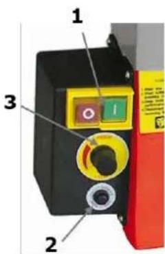
15.2.3 On-Off-switch
Switch on: Push the green button ("I") for 2 seconds. The machine begins to run.
Observe the circuit breaker reset button (2).
Switch off: Push the red button ("0").
The machine does not stop immediately! Stay as long at the machine, until the workpiece is completely stopped (Do not stop the workpiece by hand!)
15.2.1 Speed adjustment
The speed of the D300F is infinitely variable with the speed controller (3) in a range of 750 - 3200min ^-1 after switch on (1) adjustable.
text_image
1 2 316 MAINTENANCE

ATTENTION
Don't clean or do maintenance on the machine while it is still connected to the power supply:
Damages to machine and injuries might occur due to unintended switching on of the machine!
Therefore: Switch the machine off and disconnect it from the power supply be-fore any maintenance works or cleaning is carried out
The machine does not require extensive maintenance. If malfunctions and defects occur, let it be serviced by trained persons only.
Before first operation as well as later on every 100 operation hours you should lubricate all connecting parts (if required, remove beforehand with a brush all swarfs and dust).
Check regularly the condition of the security stickers. Replace them if required.
Check regularly the condition of the machine.
The good condition and perfect adjustment of the guiding rollers is essential for a smooth band guidance and a clean cut.
Store the machine in a closed, dry location.
NOTICE
Clean your machine regularly after every usage – it prolongs the machines lifespan and is a pre-requisite for a safe working environment.
Repair jobs shall be performed by respectively trained professionals only!
16.1 Maintenance plan
After each workshift:
Clean the machine and its parts with a strong jet of compressed air from wood dust and other material remains. Moving parts can also be cleaned with a brush or a soft brush. Apply a thin layer of lubricating oil to all moving parts of the machine.
After 50 hours of operation
Check the V-belts.
Determine for frayed belts cause. Check if uneven or rough surfaces and were built on the V-belt pulleys. Replace frayed or stretched belts!
16.2 Cleaning
After each workshift the machine has to be cleaned. Remove chips etc. with a suitable tool. Do not remove them by hand (cutting injury!). Remove dust as well.

NOTICE
The usage of certain solutions containing ingredients damaging metal surfaces as well as the use of scrubbing agents will damage the machine surface!
Clean the machine surface with a wet cloth soaked in a mild solution
16.3 Disposal
Do not dispose the machine in residual waste. Contact your local authorities for information regarding the available disposal options. When you buy at your local dealer for a replacement unit, the latter is obliged to exchange your old.

17 TROUBLE SHOOTING
BEFORE YOU START WORKING FOR THE ELIMINATION OF DEFECTS, DISCONNECT THE MACHINE FROM THE POWER SUPPLY.
| Trouble | Possible cause | Solution |
| Machine does not start | Switch defective | Repair switch |
| Power supply is off | Repair power supply | |
| Fuse is defective | Change fuse | |
| Circuit breaker is active | Push in the circuit button | |
| Strong vibration | Warped workpiece | Change material |
| Workpiece is wrong centered | Measure the center newly | |
| Loosen pulley | Tighten the pulley | |
| Outworn pulley | Change pulley | |
| Turning lathe is on uneven surface | Level the surface | |
| Loosen tail- or headstock | Tighten | |
| Too much speed | Adjust speed | |
| Bad turning result | bad sharpened chisel | Sharpen the chisel |
| Wrong chisel for this work | Select the right chisel | |
| Wrong adjustment of tool rest | Adjust the high and the distance of the tool rest |
MANY POTENTIAL SOURCES OF ERROR CAN BE CLEARED BY THE EXPERTLY CONNECTION TO THE ELECTRICITY GRID.

NOTICE
Should you in necessary repairs not able to properly to perform or you have not the prescribed training for it always attract a workshop to fix the problem.
18 PREFACIO (ES)
Estimado Cliente,
text_image
Technical diagram of a mechanical device with numbered components labeled 1, 2, and 321.2.3 Retén
natural_image
Technical line drawings of three different mechanical devices with numbered components (no text or symbols)22 FUNCIONAMIENTO
text_image
Diagram showing a mechanical assembly with labeled parts and directional arrows, including parts 1, 2, and 3.28.2.2 Plateau frontal
text_image
Technical diagram of a mechanical device with numbered components labeled 1, 2, and 328.2.3 Réteneur
natural_image
Technical line drawings of three different types of industrial machines, showing mechanical components without any text or symbols.29 FONCTIONNEMENT
text_image
Labeled diagram of a device showing components 1, 2, and 3 with colored parts and control buttons30 ENTRETIEN

ATTENT ION
text_image
Technical diagram of a mechanical device with numbered components labeled 1, 2, and 335.3.3 Unašeč
text_image
Technical diagram of a mechanical device with numbered parts labeled 1 through 6text_image
Technical diagram of a mechanical assembly with numbered components for identification
POKYN
text_image
Technical diagram of a mechanical device with numbered components labeled 1, 2, and 3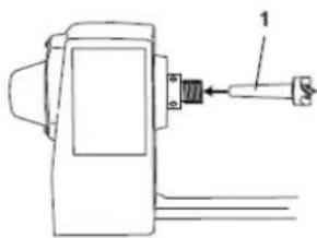
natural_image
Technical line drawing of a mechanical device with a labeled component (no text or symbols present)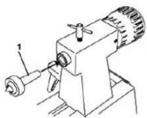
natural_image
Technical line drawing of a mechanical device with no visible text or symbols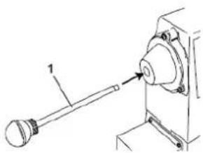
natural_image
Technical line drawing of a mechanical assembly with a tool and component (no text or symbols)43 USO
text_image
Technical diagram of a mechanical device with numbered parts labeled 1 through 6text_image
Technical diagram of a mechanical assembly with numbered components for identification
NOTA
HOOGSTE RISICO VAN LETSELS!
Arbeidsvoorwaarden
text_image
Technical diagram of a mechanical device with numbered parts labeled 1 through 650.2.2 Leunspaan instellen
- Spanhendel (4) losmaken
- Houder (1) van leunspaan op de gewenste positie brengen en weer fixeren.
- Vergrendelingshendel (3) losmaken en de hoogte van de leunspaan (2) instellen en fixeren.
text_image
Technical diagram of a mechanical assembly with numbered components, likely for assembly or maintenance instructions.
INDICATIE
With original HOLZMANN spare parts you use parts that are attuned to each other shorten the installation time and elongate your products lifespan.
IMP OR TAN T
The installation of other than original spare parts voids the warranty!
So you always have to use original spare parts
When you place a spare parts order please use the service formular you can find in the last chapter of this manual. Always take a note of the machine type, spare parts number and partname. We recommend to copy the spare parts diagram and mark the spare part you need.
You find the order address in the preface of this operation manual.
text_image
Exploded view diagram of a mechanical assembly with numbered parts for identification| No. | Specification | Qty. | No. | Specification | Qty |
| 1 | Bed | 1 | 30 | Set screw M6x8 | 1 |
| 2 | Retaining plate | 1 | 31 | Drive pully | 1 |
| 3 | PHLP HD screw M5x8 | 2 | 32 | Belt K-516 | 1 |
| 4 | Special set screw M6x8 | 1 | 33 | Set screw M6x10 | 1 |
| 5 | Handwheel | 1 | 34 | Motor pully | 1 |
| 6 | Tailstock | 1 | 35 | Power cord | 1 |
| 7 | T-lock knob bolt for tailstock | 1 | 36 | Variabel speed box | 1 |
| 8 | Cap screw M8x40 | 1 | 37 | PHLP HD screw M4x10 | 4 |
| 9 | Sleeve | 1 | 38 | Cap screw M8x25 | 1 |
| 10 | Eccentric axis | 1 | 39 | Cap screw M6x16 | 2 |
| 11 | Tailstock spindle | 1 | 40 | Motor plate | 1 |
| 12 | Lock Washer 8MM | 3 | 41 | Motor | 1 |
| 13 | Paddle switch | 1 | 42 | Warming label | 1 |
| 14 | Live center assembly | 1 | 43 | Ext retaining ring 8MM | 1 |
| 15 | Spur center | 1 | 44 | Tool rest base | 1 |
| 16 | Tailstock lock handle | 1 | 45 | Special bolt | 1 |
| 17 | Face plate-6 | 1 | 46 | Plate | 1 |
| 18 | Headstock spindle | 1 | 47 | Lock nut M8 | 2 |
| 19 | Ball bearing 6004ZZ | 1 | 48 | Sleeve | 1 |
| 20 | Ext retaining ring C40 | 1 | 49 | Eccentric rod | 1 |
| 21 | EXt retaining ring C40 | 1 | 50A | Large tool rest | 1 |
| 22 | Ball bearing 6004ZZ | 1 | 50B | Small tool rest | 1 |
| 23 | Headstock | 1 | 51 | Special bolt | 1 |
| 24 | Speed dial switch | 1 | 52 | Plate | 1 |
| 25 | Speed dial label | 1 | 53 | T-lock knob bolt for tool rest | 1 |
| 26 | Headstock spindle nut | 2 | 54 | Tool holder lock handle | 1 |
| 27 | Outboard spindel cover | 1 | 55 | Fuse | 1 |
| 28 | PHLP HD screw M4x10 | 3 | 56 | Carbon brush | 2 |
| 29 | Spec's label | 1 | 57 | Cap screw M5X8 | 4 |
54 EG-KONFORMITÄTSERKLÄRUNG/CE-CERTIFICATE OF CONFORMITY

Inverkehrbringer / Distributor
Hereby we declare that the above mentioned machines meet the essential safety and health requirements of the above stated EC directives. Any manipulation or change of the machine not being explicitly authorized by us in advance renders this document null and void.
Please consult our troubleshooting section for initial problem solving. Feel free to contact your HOLZMANN reseller or us for Customer Support!
Warranty claims based on your sales contract with your HOLZMANN retailer, including your statutory rights, shall not be affected by this guarantee declaration. HOLZMANN-MASCHINEN grants guarantee according to following conditions:
A) The guarantee covers the correction of deficiencies to the tool/product, at no charge, if it can be verified adequately that the deficiencies were caused by a material or manufacturing fault.
B) The guarantee period lasts 12 months, and is reduced to 6 months for tools in commercial use. The guarantee period begins from the time the new tool is purchased from the first end user. The starting date is the date on the original delivery receipt, or the sales receipt in the case of pickup by the customer.
C) Please lodge your guarantee claims to your HOLZMANN reseller you acquired the claimed tool from with following information:
Original Sales receipt and/or delivery receipt
Service form (see next page) filed, with a sufficient deficiency report
for spare part claims: a copy of the respective exploded drawing with the required spare parts being marked clear and unmistakable.
D) The Guarantee handling procedure and place of fulfillment is determined according to HOLZMANNs sole discretion in accordance with the HOLZMANN retail partner. If there is no additional Service contract made including on-site service, the place of fulfillment is principally the HOLZMANN Service Center in Haslach, Austria.
Transport charges for sending to and from our Service Center are not covered in this guarantee.
E) The Guarantee does not cover:
- Wear and tear parts like belts, provided tools etc., except to initial damage which has to be claimed immediately after receipt and initial check of the product.
- Defects in the tool caused by non-compliance with the operating instructions, improper assembly, insufficient power supply, improper use, abnormal environmental conditions, inappropriate operating conditions, overload or insufficient servicing or maintenance.
• Damages being the causal effect of performed manipulations, changes, additions made to the product.
• Defects caused by using accessories, components or spare parts other than original HOLZMANN spare parts. - Slight deviations from the specified quality or slight appearance changes that do not affect functionality or value of the tool.
- Defects resulting from a commercial use of tools that - based on their construction and power output - are not designed and built to be used within the frame of industrial/commercial continuous load.
F) Claims other than the right to correction of faults in the tool named in these guarantee conditions are not covered by our guarantee.
G) This guarantee is voluntary. Therefore Services provided under guarantee do not lengthen or renew the guarantee period for the tool or the replaced part.
SERVICE
After Guarantee and warranty expiration specialist repair shops can perform maintenance and repair jobs. But we are still at your service as well with spare parts and/or product service. Place your spare part / repair service cost inquiry by filing the SERVICE form on the following page and send it:
via Mail to info@holzmann-maschinen.at
or via Fax to: +43 7289 71562 4
57 GARANTÍA Y SERVICIO
PRODUCT EXPERIENCE FORM
We observe the quality of our delivered products in the frame of a Quality Management policy.
Your opinion is essential for further product development and product choice. Please let us know about your:
- Impressions and suggestions for improvement.
- experiences that may be useful for other users and for product design
- Experiences with malfunctions that occur in specific operation modes
We would like to ask you to note down your experiences and observations and send them to us via FAX, E-Mail or by post:
service inquiry spare part inquiry guarantee claim
Please describe amongst others in the problem: What has cause the problem/defect, what was the last activity before you noticed the problem/defect? For electrical problems: Have you had checked you electric supply and the machine already by a certified electrician?
3. Bitte beachten
Additional information
INCOMPLETELY FILLED SERVICE FORMS CANNOT BE PROCESSED! FOR GUARANTEE CLAIMS PLEASE ADD A COPY OF YOUR ORIGINAL SALES / DELIVERY RECEIPT OTHERWISE IT CANNOT BE ACCEPTED. FOR SPARE PART ORDERS PLEASE ADD TO THIS SERVICE FORM A COPY OF THE RESPECTIVE EXPLODED DRAWING WITH THE REQUIRED SPARE PARTS BEING MARKED CLEARLY AND UNMISTAKABLE. THIS HELPS US TO IDENTIFY THE REQUIRED SPARE PARTS FASTLY AND ACCEL- ERATES THE HANDLING OF YOUR INQUIRY.